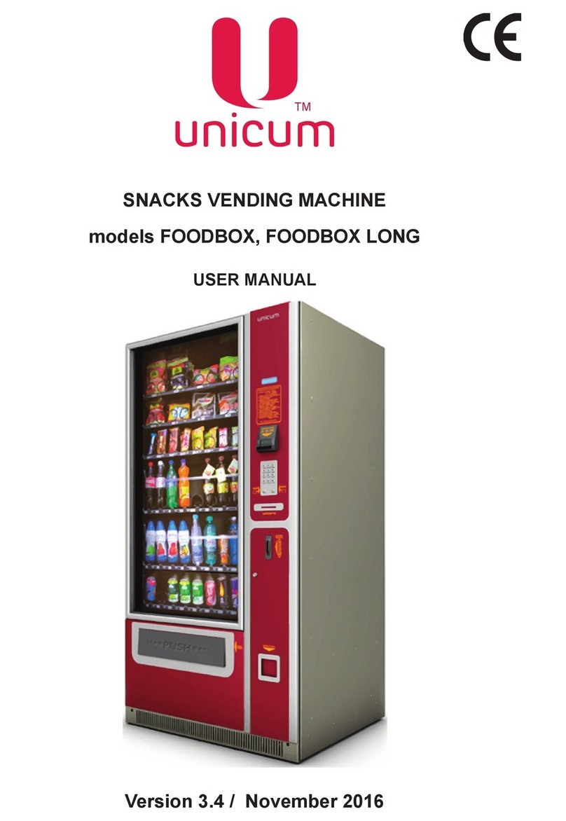
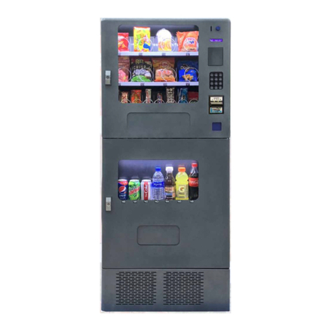
Unicum Foodbox Touch Lift User manual

SNACK VENDING MACHINE
models FOODBOX TOUCH, FOODBOX LONG TOUCH,
FOODBOX LIFT TOUCH
USER MANUAL
Version 1.3 / December 2018
ТМ

FOODBOX TOUCH, FOODBOX LONG TOUCH, FOODBOX LIFT TOUCH
Page 3Version 1.3 / December 2018
ТМ
CONTENT
1.0 GENERAL INFORMATION ....................................................................................... 4
2.0 SAFETY .................................................................................................................... 6
3.0 SPECIFICATIONS ..................................................................................................... 7
4.0 VENDING MACHINE DESCRIPTION ....................................................................... 8
4.1 Interior ................................................................................................................. 8
4.2 Control compartment........................................................................................... 9
4.3 Selling process.................................................................................................... 10
4.4 Vending machine components ............................................................................ 11
4.4.1 Giving out compartment ............................................................................ 11
4.4.2 Control compartment................................................................................. 11
4.4.3 Touch screen ............................................................................................. 11
4.4.4 Lock........................................................................................................... 12
5.0 INSTALLATION ......................................................................................................... 13
5.1 Location selection ............................................................................................... 13
5.2 Safety precautions .............................................................................................. 14
5.3 Installation ........................................................................................................... 14
5.4 Electrical connection ........................................................................................... 15
5.5 Wall mounting...................................................................................................... 15
5.6 Vending machine activation ................................................................................ 16
5.7 Vending machine deactivation ............................................................................ 16
5.8 Products loading ................................................................................................. 17
6.0 COOLING UNIT......................................................................................................... 18
6.1 Operating Modes................................................................................................. 18
7.0 CONTROL ................................................................................................................. 20
7.1 Controller board .................................................................................................. 20
7.2 Service buttons .................................................................................................. 22
8.0 USER MENU ............................................................................................................ 23
9.0 SERVICE MENU - MENU TECHNICIAN................................................................... 25
9.1 System ................................................................................................................ 27
9.1.1 General..................................................................................................... 27
9.1.2 Security .................................................................................................... 28
9.1.3 Franchising............................................................................................... 29
9.1.4 Resets ...................................................................................................... 30
9.1.5 Power ........................................................................................................ 31
9.1.6 EVA-DTS ................................................................................................... 32
9.1.7 Modem ...................................................................................................... 33
9.1.8 Ethernet..................................................................................................... 35
9.1.9 About ......................................................................................................... 36
9.2 Snack .................................................................................................................. 37
9.2.1 Service ...................................................................................................... 37
9.2.2 Setup ......................................................................................................... 38
9.2.3 Thermal setup ........................................................................................... 42
9.3 Payment Systems ............................................................................................... 45
9.3.1 Changer..................................................................................................... 45
9.3.2 General Setup ........................................................................................... 47
9.3.3 Change Setup ........................................................................................... 48
9.4 Errors .................................................................................................................. 50
10.0 SERVICE MENU - OPERATOR MENU................................................................... 52
11.0 LOADING PRODUCT IMAGES TO VENDING MACHINE...................................... 52
12.0 CHANGING THE CONFIGURATION OF SHELVES............................................... 54
13.0 MAINTENANCE ...................................................................................................... 59
FOODBOX TOUCH, FOODBOX LONG TOUCH, FOODBOX LIFT TOUCH
Page 4Version 1.3 / December 2018
ТМ
1.0 GENERAL INFORMATION
The manual contains the general information about vending machines and their software, necessary for
their commissioning, operation, maintenance, as well as the general information about vending machine
software.
The manual is written for engineering and technical personnel, conducting vending machine mainte-
nance and authorized for working with this type of electrical installations.
Failure to comply with the manual requirements may lead to injuries, damage to the equipment and
result in discontinuation of warranty obligations. Before installing and using the vending machine carefully
read the requirements put down in this manual, because it contains critical information about the safe in-
stallation and operating and maintenance instruction.
Knowledge of safety regulations requirements is necessary for teaching the users to correctly operate
vending machines.
The vending machine customer is responsible for proper training and informing the service personnel,
and controlling the fulfilment of technical documentation requirements.
The vending machine manufacturer denies any responsibility for any injuries and damages resulting
from the following circumstance:
- unauthorized modernization;
- incorrect installation;
- incorrect connection to the power supply;
- inadequate cleaning and servicing;
- misuse of the vending machine equipment;
- the use of non-original spare parts.
Under no circumstances the manufacturer is obligated to compensate the possible damage, resulting
from the forced shut down of the vending machine as a result of a malfunction.
Thevendingmachinemodels:FoodboxTouch,FoodboxLongTouchиFoodboxLiftTouchareintend-
ed for retail selling and storage in the specified temperature regime the previously packed food products
(snacks) and cold drinks. The Foodbox Lift Touch model uses a lift for more careful giving out of products.
Vending machines use a touch screen with graphic user menu interface in the selling mode and a ser-
vice menu in the vending machine servicing mode.
Products recommended for loading into the vending machine:
•The piece goods in sealed package, ruling out the possibility of spilling crisps, breakfast cereals,
meat snacks, baked breads, chocolate bars, packed cookies, packed peanuts, packed croissants, etc.);
•Drinks in plastic and TetraPak packaging up to 0.5 l in capacity;
•Drinks in aluminum cans up to 0.33 l in capacity;
•Drinks in plastic bottles up to 0.5...0.6 l in capacity.
Not recommended for loading into the vending machine:
• Products and drinks in glass containers;
• Products in packaging which does not exclude the possibility of the contents spillage;
• Products without packaging;
• Dairy products in soft packaging.

FOODBOX TOUCH, FOODBOX LONG TOUCH, FOODBOX LIFT TOUCH
Page 5Version 1.3 / December 2018
ТМ
Manufacturer’s warranty
The manufacturer’s warranty during the warranty period covers all vending machine units and
assemblies, except for malfunctions, arising from non-observance of current maintenance documentation
requirements by the customer or due to any mechanical failures.
The following components are excluded from the manufacturer’s warranty:
•Fuses;
•Control board batteries.

FOODBOX TOUCH, FOODBOX LONG TOUCH, FOODBOX LIFT TOUCH
Page 6Version 1.3 / December 2018
ТМ
2.0 SAFETY
For safe operation of the vending machine comply with the rules given below:
- before starting the vending machine operation read and understand this manual;
- the vending machine can be used for selling the cold drinks in plastic bottles and cans and packed
snacks;
- during the transportation and technical maintenance follow the requirements given in this manual;
- the vending machine should be installed on a level surface;
- the vending machine installation and maintenance should be carried out by qualified technicians
only;
- the vending machine is not intended for use by persons (including children) with physical, sensory
or intellectual limitations, unless they are under the supervision of a person, responsible for their safety, or
were instructed of how to use the vending machine;
- if the power cord is damaged the vending machine cannot be used. The power cord should be re-
placed by skilled technician only;
- never connect or disconnect the vending machine power plug with wet hands;
- the vending machine is intended for operation indoors only at the ambient air temperature from 5 to
35°C, relative air humidity up to 80% at 25°C, and atmospheric pressure from 84.0 to 106.7 kPa (630-800
mmHg);
- the vending machine should not be transported when loaded with products;
- don’t clean the vending machine by pressure water jets;
- use genuine spare parts only;
- when connecting the vending machine to the power network the use of adapters, extenders and
multi-pin plugs are prohibited;
- switching on several vending machines by using one switch at the central electric panel is prohib-
ited. This may damage the vending machines;
- connecting the vending machine to the power network without grounding is prohibited;
- any vending machine changes or modifications without manufacturer’s notification are prohibited!
Otherwise, the manufacturer assumes no warranty liabilities.

FOODBOX TOUCH, FOODBOX LONG TOUCH, FOODBOX LIFT TOUCH
Page 7Version 1.3 / December 2018
ТМ
3.0 SPECIFICATIONS
Vending machine
Parameters Foodbox Touch Foodbox Long Touch Foodbox Lift Touch
Height, no more than 1850 mm 1850 mm 1850 mm
Width, no more than 1000 mm 1280 mm 1020 mm
Depth, no more than 820 mm 820 mm 820 mm
Weight, no more than 300 kg 370 kg 300 kg
Electrical connection ~230В/50Гц ~230В/50Гц ~230В/50Гц
Power consumption max. 700 W max. 700 W max. 700 W
Environmental Limits + 5...+35 0С+ 5...+35 0С+ 5...+35 0С
Cooling unit
- cooling agent (coolant) - R134a;
- ventilated evaporator;
- the adjustable temperature in the refrigerated zone: from 4 to 10 °C.

FOODBOX TOUCH, FOODBOX LONG TOUCH, FOODBOX LIFT TOUCH
Page 8Version 1.3 / December 2018
ТМ
4.0 VENDING MACHINE DESCRIPTION
4.1 Interior
10
1
2
3
4
5
6
7
8
9
NOTE: The Foodbox Lift Touch model uses a lift for more careful products giving out.
Figure 1
1 Shelf for products 6 Slot for coins
2 Printer for receipts (option) 7 Lock
3 Control compartment 8 Change tray (coins)
4 Touch screen 9 Product dispensing tray
5 Slotforbills/plug 10Door

FOODBOX TOUCH, FOODBOX LONG TOUCH, FOODBOX LIFT TOUCH
Page 9Version 1.3 / December 2018
ТМ
4.2 Control compartment
1
2
3
4
5
6
7
8
9
10
11
12
Figure 2
1 Printer for receipts (option) 7 Box for coins
2 Service buttons + USB PC connector 8 Touch screen
3 Controlboards 9Slotforbills/plug
4 Cash acceptor 10 Slot for coins
5 Change giving out motor (option) 11 Lock
6 Coin drawer 12 Change tray (coins)

FOODBOX TOUCH, FOODBOX LONG TOUCH, FOODBOX LIFT TOUCH
Page 10Version 1.3 / December 2018
ТМ
4.3 Selling process
In fig. 3 the products selling algorithm that is implemented in the vending machine is shown.
Enter a credit that is required for
buying a product
The lift approaches the cell with the selected product
(for Foodbox Lift Touch only)
Select a product on the touch screen
Confirm the selection
The screw of the cell with the selected product
makes one complete revolution through 3600
The product falls to the giving out tray
Figure 3

FOODBOX TOUCH, FOODBOX LONG TOUCH, FOODBOX LIFT TOUCH
Page 11Version 1.3 / December 2018
ТМ
4.4 Vending machine components
4.4.1 Giving out compartment
Product dispensing compartment occupies the largest volume of the vending machine and is closed
by a glass door, which is blocked by a slide-out panel of the control compartment.
The product dispensing compartment dimensions allow installing up to 6 (optionally - up to 8) shelves
with cells of different configurations:
•cells for wide products with two synchronously rotating spirals (double cells);
•single cells with one spiral;
•one-and-a-half cells with one spiral.
Shelvesaredesignedinsuchawaythattheycanbeeasilyslidinandoutforquickloading/unloading
the products. Shelves are closed by the door with a glass unit. Products by using the spirals are fed to the
product dispensing tray. Optical sensors located at the dispensing tray register the product release. The
customer takes the product from the tray. In the lower part of the vending machine, there’s a ventilation
casing.
In the lower part of the dispensing compartment, there’s a cooling unit, maintaining the product
storage temperature conditions that are preset by the user.
4.4.2 Control compartment
The control compartment is a rectangular metal compartment, isolated from the product dispensing
compartment. The control compartment is closed by a slide-out panel. The control compartment
accommodates the following:
- the vending machine main control board (hereinafter - the controller);
- payment systems (cash acceptor, coin drawer, card reader);
- control boards;
- power pack;
- receipt printer;
- coin box;
- touch screen.
NOTE: depending on your order the presence or absence of these elements is possible.
Control compartment panel, as well as product dispensing compartment door, are closed by using
a lock.
4.4.3 Touch screen
On the front panel of the control compartment, there’s a touch screen. In the selling mode, the user
interface is displayed, by which the customer can buy the desired product in the vending machine. The
screen is also used for displaying all functional messages.
In the service mode, the screen displays the menu technician or operator menu with the necessary
settings.

FOODBOX TOUCH, FOODBOX LONG TOUCH, FOODBOX LIFT TOUCH
Page 12Version 1.3 / December 2018
ТМ
4.4.4 Lock
The vending machine is supplied with the RIELDA lock, which can be programmed for the required
key set that permits using one work key for several RIELDA locks at once, as well as easily change any
lock combination for the new work key in case of old key loss, theft or breakage.
Figure 4
ATTENTION!
The lock programming operations should be executed with the vending machine door
open! Otherwise, the door will be locked by a latch.
To return the lock to the programming position only use the master key, used for the
latest programming!
Reference notch
Closed
Open/programming
900Master key Work keys
The lock is supplied together with three keys (fig. 4):
- one master key - a GOLDISH key used only for lock programming;
- two work keys - SILVERYkeysusedforthevendingmachinedooropening/closing.
The lock may be in two positions:
- working position (“locked” position - fig. 4);
- programming position (“open” position - fig. 4).
Thevendingmachineissuppliedwithaready-programmedlock.Toopen/closethevendingmachine
door insert the SILVERY work key (sfig. 4) and turn it in the lock by 90° in the required position (fig. 4).
To program the lock for another work key (e.g. for using one work key for several vending machines
or in the case of the work key loss) it's necessary to execute the following operations with the vending
machine door OPEN:
- insert the master key («close» position - fig. 4), by which the lock was the last time programmed or
the one that was supplied with the lock (for initial programming), into the lock. Secure the master key in the
lock for at least 1 second. Then turn the key by 900 in the direction of the reference notch (fig. 4).
- while holding shutting off device of the door in order to avoid a spontaneous turn of the lock, remove
the master key from the lock and insert them into the new master key , which you want to program the
lock. If you want to program the lock on the same master key, don’t remove the master key from the lock.
- then turn the master key by 90° to the opposite direction («closed» position - fig. 4).
- takeoutthemasterkeyfromthelockandputitinasafeplace.Toopen/closethelockusethework
keys supplied with your new master key.

FOODBOX TOUCH, FOODBOX LONG TOUCH, FOODBOX LIFT TOUCH
Page 13Version 1.3 / December 2018
ТМ
5.0 INSTALLATION
5.1 Location selection
When selecting a location for the installation of the vending machine take into consideration the
following:
- the vending machine is not intended for operation in the open air and should be installed only inside
dry premises with the ambient temperature maintained in the working range (see specifications).
- for the installation of the vending machines in the open air use the additional heating and put the
vending machine into the special casing (thermal box).
- the vending machine shouldn’t be exposed to direct sunlight.
- the surface for the vending machine installation should be hard and flat.
- the vending machine door should open entirely.
- it’s prohibited to install the vending machine with an inclination exceeding 2°.
- it’s prohibited to install the vending machine on carpeting or other electrostatic coatings.
- it’s prohibited to close ventilation slots in the vending machine case.
- when installing the vending machine in the heated spaces it should be located no less than 1 m
away from heating appliances.
- the distance from the vending machine rear wall to other objects should be no less than 0.1 m.
Figure 5 - Vending machine installation
no more than 20
at least 0.1m
heating appliance
room wall
A B C
no more than 20

FOODBOX TOUCH, FOODBOX LONG TOUCH, FOODBOX LIFT TOUCH
Page 14Version 1.3 / December 2018
ТМ
5.2 Safety precautions
When transporting the vending machine to the installation location use mechanical or automatic fork
loader.
- the vending machine should be transported in a vertical position on its own base;
- it’s forbidden to drop and overturn the vending machine;
- it’s forbidden to use ropes, strands, cables, etc. for the vending machine movement;
- before moving the vending machine make sure that the power cord is disconnected from the mains;
- after transportation of the vending machine for long distances at which it was exposed to high level
of vibration or impacts, check the contact connections between the elements and functional nodes, as well
as the mounting of the elements and functional nodes.
5.3 Installation
Remove the shipping package and packaging material from the vending machine. Contact the
supplier if the vending machine has any visible damaged:
- before the first activation, hold the vending machine in the premise at room temperature for at least
5 hours. Make sure there’s no condensate on the vending machine internal elements and, in particular, on
the touch screen and door;
- carefully move the vending machine by using the fork loader to the placement location and lift it for
20...30 cm;
- secure the loader;
- by using a S=10 mm spanner unscrew the fastening bolts and remove the wooden supports. It’s
recommended to put bolts with washers and wooden supports into a plastic bag together with packaging
for storage;
- take four supporting feet, packed for the duration of transportation into the product dispensing tray,
unpack them and screw into the holes in the vending machine base corners;
- lower the vending machine to the placement location and remove the forklift from under the ma-
chine;
- by using a S=34 mm spanner adjust the supporting feet, so that the vending machine is level in a
horizontal plane;
- use a level for ensuring the level installation;
- after the vending machine installation and levelling take the ventilation cover, packed for the dura-
tion of transportation into the product dispensing tray, and install it on the vending machine by using the
screws from the fitting kit (fig. 6).
Figure 6- Installation of ventilation cover

FOODBOX TOUCH, FOODBOX LONG TOUCH, FOODBOX LIFT TOUCH
Page 15Version 1.3 / December 2018
ТМ
ATTENTION!
To prevent the vending machine from overturning it’s prohibited to open the vending
machine doors and pulling out the shelves until the vending machine is securely fixed
on the mounting surface!
5.4 Electrical connection
Thevendingmachineissuppliedreadyforconnectionbyusingapowercordtoa~230V/50Hz
single-phase AC power circuit. The vending machine should be connected to the wall outlet with grounding
contact.
After the electrical connection, the vending machine plug should be accessible.
5.5 Wall mounting
The vending machine design permits its mounting to the wall. The wall mounting helps preventing
the vending machine from overturning in the cases of damaging and breaking.
To mount the vending machine to the wall:
- take the rests and self-tapping screw packed for the duration of transportation into the product
dispensing tray;
- fix the rests to the vending machine by using four screws;
- move the vending machine close to the wall;
- mark the location of mounting holes by a marker;
- move the vending machine away from the wall and drill 2 blind holes for the screw plugs installation;
- install the screw plugs and move the vending machine to the wall, so that the fixing holes in the wall
match with the holes in the rests. Then fix the vending machine by using self-tapping screws.
Figure 7 - Vending machine wall mounting
1 - Self-tapping screw
2 - Screw plug
Note: When fixing the vending machine to the wall, at the first place fix the wall mount rests to the
vending machine, and only then proceed fixing the vending machine to the wall!

FOODBOX TOUCH, FOODBOX LONG TOUCH, FOODBOX LIFT TOUCH
Page 16Version 1.3 / December 2018
ТМ
5.6 Vending machine activation
To activate the vending machine proceed as follows:
- connect the power cords in accordance with fig. 8;
- plug the power cord into an electrical outlet;
- open the control compartment door (see section 4.4.4);
- set the MAINS switch to ON position;
- close the control compartment door.
Figure 8 - Power cord connection
5.7 Vending machine deactivation
To deactivate the vending machine proceed as follows:
- open the control compartment door (see section 4.4.4);
- set the MAINS switch to OFF position;
- close the control compartment door;
- disconnect the power cord plug from the electrical outlet.

FOODBOX TOUCH, FOODBOX LONG TOUCH, FOODBOX LIFT TOUCH
Page 17Version 1.3 / December 2018
ТМ
5.8 Products loading
After the completion of installation and vending machine adjustment load the vending machine with
products:
- open the vending machine door, so it does not interfere with shelves moving-out;
- pull the shelf latch, located on the left, following which pull out the shelf up to the stop by firmly hold-
ing the shelf by its lower part. To facilitate loading the upper shelves are inclined when pulled out (fig. 9);
Figure 9 - Shelves loading
- start loading from the front, don’t leave hollow spaces. Insert the products from above between the
spiral turns. The label with product name should be turned towards the showcase, so it’s well seen by the
customer. The products shouldn’t be squeezed between the spiral turns;
- after the loading fit the shelves back into the vending machine up to the fixed position;
- put the price tags into the groove for price tags (fig.10).
Figure 10 - Price tags installation
ATTENTION!
To prevent the vending machine overturning pull out one shelf at a time, goods should
be laid in such a way, that the space for falling into the product dispensing tray is free
from protruding parts of other products or shelves! The shelves should be pushed all
the way back!

FOODBOX TOUCH, FOODBOX LONG TOUCH, FOODBOX LIFT TOUCH
Page 18Version 1.3 / December 2018
ТМ
6.0 COOLING UNIT
The cooling unit performance control is executed by scanning 3 temperature sensors:
- sensor No.1 - is located in the lower part of the product dispensing tray;
- sensor No.2 - is located in the upper part of the product dispensing tray;
- sensor No.3 - is located on the cooling unit evaporator (fig. 11).
Notice:
Recommended temperature settings:
- min.temperature4±2°С;
- max.temperature10±2°С;
- min.evaporatortemperature1±1°С;
- max.evaporatortemperature5±1°С.
1
2
Figure 11 - Location of temperature sensor No. 3
1 - Temperature sensors
2 - Buckles
ATTENTION!
To maintain the correct operating mode of the cooling unit, it’s important that the tem-
perature sensor No. 3 is installed correctly. It should be securely fixed on the next to
last evaporator elbow as shown in fig. 4. The sensor installation should be executed
outside the vending machine. After placing the cooling unit inside the vending machine
the sensor connector should be connected to the temperature sensor wiring harness.
6.1 Operating Modes
The cooling unit operating mode control is executed by the vending machine controller. There are 4
modes of the cooling unit operation:
- standby;
- defrosting;
- cooling;
- anti-icing.
In each mode there are the cooling unit activation and deactivation, evaporator fan activation, and
deactivation, temperature sensors monitoring.
When activating the vending machine the cooling unit is switched to a STANDBY mode for two
minutes. The further operation is taken place in accordance with the stabilized condition algorithm.
If when activating the vending machine the evaporator temperature (sensor No.3) is lower than the
evaporator temperature minimum value, the controller is switched to DEFROSTING mode. When the
temperature at this sensor reaches the minimum value or higher, the cooling unit switches to STANDBY
mode.

FOODBOX TOUCH, FOODBOX LONG TOUCH, FOODBOX LIFT TOUCH
Page 19Version 1.3 / December 2018
ТМ
Standby
In the standby mode, the cooling unit is deactivated, the evaporator fan operates in accordance with
the user-defined mode, and the temperature sensors are monitored.
If the temperature at sensor No.1 exceeds the value, specified in the (Max. temperature) menu item, and
the defrosting time is expired - the unit switches to COOLING mode.
Defrosting
In the defrosting mode, the cooling unit is deactivated, the evaporator fan operates in accordance
with the user-defined mode, the temperature sensors are monitored.
The duration of the defrosting mode is determined by defrosting time, specified in the (Defrosting
time) service menu item. Upon completion of the specified time period the unit switches to STANDBY
mode. The duration of defrosting is also affected by sensor No. 3 - at the evaporator temperature below
the minimum value the unit switches to the defrosting mode or remains in this mode until the evaporator
temperature exceeds the minimum value.
Cooling
In the cooling mode, the unit is activated, the evaporator fan operates in accordance with the user-
defined mode, the temperature sensors are monitored.
The cooling unit operating time may not exceed 30 minutes. Upon expiration of this period the unit is
deactivated and after the additional two minutes the controller switches to STANDBY mode.
In the cases, if during the cooling unit operation the temperature at sensor No.1 lowered down to the tem-
perature, specified in (Min. temperature) menu item, the unit is deactivated and after the additional two
minutes, it switches to STANDBY mode.
If the temperature at sensor No. 3 is below the value specified in (Min. evaporator temp.) menu
item, the cooling unit is deactivated and switches to ANTI-ICING mode
Anti-icing
The anti-icing mode is used for preventing the cooling unit icing. In this mode the unit is deactivated,
the temperature value at sensor No.3 is monitored.
Upon reaching the value preset in the (Evaporator max. temp.) menu item, the controller switches
to the STANDBY mode. To reduce the possibility of icing use the recommended values of temperature
settings.
Evaporator fan
The evaporator fan operation mode can be changed by choosing the required mode in the service
menu (menu item Fan control):
- always on (menu item Always on);
- activated only in the cooling mode (menu item only when cooling);
- the fan operates in the cooling and defrosting modes (menu item Cooling and defrosting).
When activating the vending machine the evaporator fan is activated automatically, regardless of its
operating settings. When changing the cooling unit operation to COOLING or DEFROSTING mode the fan
will operate in accordance with the selected mode.

FOODBOX TOUCH, FOODBOX LONG TOUCH, FOODBOX LIFT TOUCH
Page 20Version 1.3 / December 2018
ТМ
7.0 CONTROL
7.1 Controller board
Controlling the operation of vending machine assemblies and equipment is executed by the control
board(hereinafter–controller),whichislocatedinthecontrolsection(fig.2pos.З).
The vending machine can operate in two modes in accordance with the embedded software algorithm
- the control program (hereinafter – firmware):
- sales mode (main operating mode);
- service mode (designed for specialists).
The main mode of operation is the sales mode. In this mode, the customer service is carried out
(products selling, storage and giving out). Entry in this mode is realized immediately after the controller
activation.
The service mode is intended for testing the vending machine equipment, setting the parameters
of assemblies and equipment, controlling the vending machine critical parameters, price management.
Changing to the service mode is executed by pressing the service keys (see above).
1. A button for accessing the operator menu (used as a backup button in the cases when the service
button is not connected).
2. A button for accessing the menu technician (used as a backup button in the cases when the ser-
vice button is not connected).
3. USB-flash drive connector.
4. The connector is not used.
5. Modem connector.
6. RS232 card reader connector.
Figure 12 - Main Board (controller)
1
2
4
5
9 8 3 7
6
10
11
12
This manual suits for next models
2
Table of contents
Other Unicum Vending Machine manuals
Popular Vending Machine manuals by other brands

Bianchi
Bianchi VEGA 600 Installation and maintenance manual

Jofemar
Jofemar vision multiseller Installation and maintenance guide

Maytag
Maytag Dixie-Narco Beverage Max DN55 Series Instructions of instalation and use

BRAVILOR BONAMAT
BRAVILOR BONAMAT Rivero Turbo Operator's manual

NW Global Vending
NW Global Vending Festival Installation - use - maintenance

Crane
Crane BevMAX Refresh 4 5800-4 Operation guide