3
© by NECTA VENDING SOLUTIONS SpA 0404 211-02
USING THE VENDING MACHINE FOR
PACKAGED PRODUCTS
Adifferentsalepricecanbesetforeachproductselection
by the machine electronic control. The various functions
areprogrammedthroughtheselectionkeypadwithoutany
need for additional equipment.
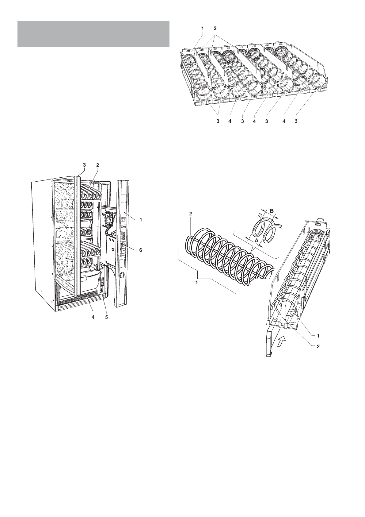
Allmodels are equipped with variableconfiguration trays,
addingorremovingdividers,spiralsandratiomotors;there-
fore the machine can be easily suited to specific needs.
All trays are preset for the operation of up to 8 selections
(maximum setting).
The product holders are equipped with independent mo-
tors and spirals; each selection will continue its operation
autonomously even if the other selections are discon-
nected.
Thisvending machineshouldonlybeusedtosell and
dispense packaged products that do not need refrig-
eration to be preserved.
Strictly comply with the producer’s specifications
regarding storage temperature and expiry date for
each product.
Any other use is unsuitable and thus potentially dan-
gerous.
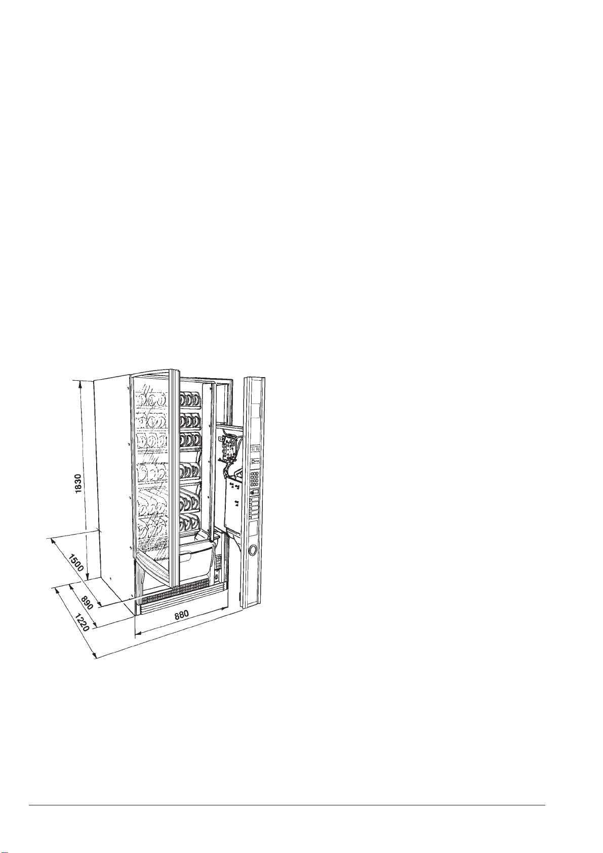
POSITIONING THE VENDING MACHINE
The vending machine is not suitable for outdoor installa-
tion.Itmustbepositionedinadryroomwherethetempera-
tureremainsbetween5°Cand32°C,andnotwherewater
jets are used for cleaning (e.g. in large kitchens, etc.).
The machine should be placed close to a wall.
Theventilationsystem allowsthebackpanel tobeleaned
against the wall, thus saving space, as air is drawn from
under the machine and exhausted through a grille at the
front.
Warning!
Incorrectventilationmaycompromisetheproperfunc-
tioning of the cooling unit.
The machine should be positioned with a maximum incli-
nation of 2°.
Ifnecessaryprovideproperlevellingbywayoftheadjust-
able feet included.
WARNING FOR INSTALLATION
The machine installation and the following mainte-
nance operations should be carried out by qualified
personnel only, who are trained in the correct use of
the machine according to the standards in force.
The machine is sold without payment system, therefore
the installer of such a system is responsible for any
damage to the machine or to things and persons caused
byfaultyinstallation.
The integrity of the machine and compliance with the
standardsoftherelevantsystemsmustbecheckedat
least once a year by qualified personnel.
PRECAUTIONS IN USING THE MACHINE
The following precautions will assist in protecting the
environment:
- use biodegradable products only to clean the machine;
- adequately dispose of all containers of the products
used for loading and cleaning the machine;
- keep the machine away from heat sources;
- regularly check the condition of the door seal to limit
any heat dispersion;
- limit as much as possible door opening time during
loading operations to avoid temperature increase
inside the cabinet and subsequent power consumption.
WARNING FOR SCRAPPING
Wheneverthemachineistobescrapped,thelawsinforce
regarding environment protection should be strictly ob-
served. More specifically:
- ferrous and plastic materials and the like are to be
disposed of in authorized areas only;
- insulating materials should be recovered by qualified
companies;
- the gas inside the cooling unit, regardless of the type
(see the identification plate), should be recoveredby
qualified companies by means of special equipment.