Nectre Fireplaces FS 800 User manual
1
Installation & Operating Instructions
Nectre 800 Wall Heater
100% Australian Made
Pecan Engineering Pty Ltd
13 Acorn Road
DRY CREEK SA 5094
ph. (08) 8349 8332 Fax. (08) 8260 6643
Toll Free 1800 636 301

2
CONTENTS
SAFETY PRECAUTIONS ................................................................................3
INSTALLATION CHECKLIST ..........................................................................4
PARTS SUPPLIED ..........................................................................................4
INSTALLATION IN DETAIL .............................................................................5
NECTRE 800 WALL HEATER – SUGGESTED FRAMING .............................9
DOOR GLASS ...............................................................................................11
DOOR GASKET.............................................................................................11
FIREBRICKS .................................................................................................12
LIGHTING YOUR FIRE .................................................................................12
INITIAL OPERATION PERIOD......................................................................12
GENERAL OPERATION................................................................................13
OVERNIGHT BURN ......................................................................................13
BAFFLE PLATE LOCATION..........................................................................14
FAN SERVICE...............................................................................................15
CLEANING THE FIREBOX............................................................................15
CONTROLS...................................................................................................15
TEN YEAR WARRANTY:- .............................................................................16
REPLACEABLE COMPONENTS OF THE HEATER.....................................17

3
SAFETY PRECAUTIONS
This heater must be installed to the specifications and clearances listed on the
compliance plate to ensure your safety. Variances from these specifications will
void your warranty and could cause a serious house fire.
To ensure compliance with the relevant Australian Standards, your heater must
be installed with the recommended flue system.
Never place furniture, paper, wood, clothes airers etc near heater.
DO NOT burn litter or treated wood, as fumes could be dangerous to your health
and the health of your neighbours.
DO NOT burn green or wet wood as it will reduce the efficiency of your
heater and could cause a dangerous fire.
Always operate with the door in the closed position.
Pecan Engineering Pty Ltd accept no liability whatsoever for interpretation of
AS/NZS 2918:2001.
WARNING: The heater must no be operated without the floor protector installed
as heat radiation from the glass door may burn floor surfaces.
WARNING: DO NOT BURN FLAMMABLE LIQUIDS OR AEROSOLS TO
START OR REKINDLE THE FIRE.
WARNING: DO NOT USE FLAMMABLE LIQUIDS OR AEROSOLS
IN THE VACINITY OF THIS APPLIANCE WHEN IT IS OPERATING.
WARNING: DO NOT STORE FUEL WITHIN HEATER INSTALLATION
CLEARANCES.
WARNING: WHEN USING THIS APPLIANCE AS AN OPEN FIRE USE A
FIRESCREEN.
WARNING: OPEN AIR CONTROL BEFORE OPENING FIRING DOOR.
CAUTION: THIS APPLIANCE SHOULD NOT BE OPERATED WITH A
CRACKED GLASS.
CAUTION: THIS APPLIANCE SHOULD BE MAINTAINED AND OPERATED AT
ALL TIMES IN ACCORDANCE WITH THESE INSTRUCTIONS.
CAUTION: THE USE OF SOME TYPES OF PRESERVATIVE TREATED
WOOD AS A FUEL CAN BE HAZARDOUS.
Recommended Fuel: Any dry hardwood that has been seasoned for at least 8
months. All fuel should be stored with protection from the weather to minimise
moisture content.

4
INSTALLATION INFORMATION
A licensed accredited installer should install all wood heaters. Please ask
retailer to locate an installer.
All warranty is void unless installed by an authorised installer.
INSTALLATION CHECKLIST
(Refer to next page for more detailed instructions)
Minimum clearances to combustible materials:-
Supplied steel cross bearer to rear wall 25mm
Side wall within enclosure to side of heater 200mm
Front of heater to existing wall in house 500mm
Underside clearance to base of heater 200mm
Ceiling clearance to top of heater 1170mm
Flue Requirements:-
Standard 150mm diameter double cased flue kit (AS 2918)
300mm diameter outer casing extending from appliance to a minimum
300mm above ceiling penetration.
Clearance between outer casing and ceiling minimum of 25mm, eg.
350mm hole in ceiling
Floor Requirements if floor is heat sensitive:-
If base of heater is a 590mm or more from the floor, then floor protector
must be minimum of 6mm fibro cement sheet extending under heater and
300mm in front of door opening and 200mm either side
If base of heater is less than 590mm from floor, then floor protector must
comply with AS/NZ 2918:2001, clause 3.3.3.
Other Requirements:-
Front wall of enclosure must be comprised of non combustible material
Enclosure around heater must include vents top and bottom
Set up for fan to be connected to mains power supply, eg. Install power
socket in enclosure, or access for extension cord to fan.
PARTS SUPPLIED
•Nectre 800 Wall Heater (includes facia trim and fan)
•100mm x 1130mm long C-section cross bearers (Qty = 2)
•100mm x 500mm long C-section support channels (Qty = 2)
•Steel framing for front wall and heater surround (No. pieces = 4)
•Nuts, bolts, and washers for fastening channels and heater (8 of each)
5
INSTALLATION IN DETAIL
The Nectre 800 Wall Heater is designed to be built in to a wall enclosure and
may be elevated from the floor. The wall enclosure may be constructed of non
combustible material such as masonry or Hebel blocks or may be constructed of
timber and steel framing and clad with plaster board and fibre-cement sheet (see
drawing).
Installation must comply with the standard AS/NZS 2918:2001. (Domestic Solid
Fuel Burning Appliances – Installation)
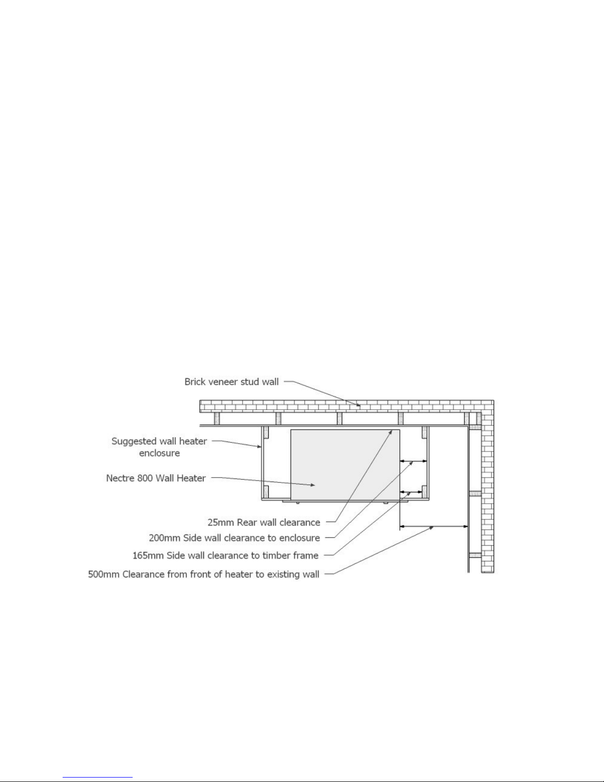
Clearances
The clearances from the wall heater to combustible materials must not be less
than the following:
(Note that plasterboard over a timber frame is a combustible surface)
Rear wall clearance - 25mm (within the enclosure)
Side wall clearance - 200mm (within the enclosure)
Front of heater to existing wall - 500mm
Underside clearance - 200mm
Ceiling clearance - 1170mm

6
Floor Protection
Where the floor material is heat sensitive then a floor protector shall extend under
and in front of the heater.
•If the base of the heater is 590mm or more above the floor then the floor
protector must be a minimum of 6mm fibro cement sheet 1metre wide
extending under the heater and 300mm in front of the wall. (300mm in
front of the door opening and 200mm either side). An alternative to fibro
cement in front of the fire opening could be a slate hearth or row of
300mm tiles.
•If the base of the heater is less than 590mm above a heat sensitive floor
then a hearth in front of the heater shall be used according to clause 3.3.3
(b)(iii) of AS/NZ 2918:2001. This shall be constructed of continuous heat
tolerant material not less than 15 mm thick. The top surface of the floor
protector shall be of heat resistant material. The hearth shall be separated
from the floor by means of heat resistant spacers forming an air gap of not
less than 25 mm between the hearth and the floor. The total plan area of
the air gap shall be not less than 90% of the area of the hearth. The
hearth shall be a minimum of 1 m wide (200 either side of the firebox
opening) and 500mm deep from firebox opening and shall be ventilated on
each side with an opening of 25 x 300 or an area calculated by the hearth
perimeter x 2.
Ventilation
The enclosure around the heater must be ventilated. Fit vents with a “free area”
of at least 14000 mm² at the top and bottom of the enclosure. (Standard wall
vents 230mm x 150mm can provide 7000 mm² each.) This applies to non
combustible enclosures as well as framed enclosures. The purpose of the vents
is to allow cooler air to be drawn into the enclosure through the bottom vent, and
warm air out through the top vent via natural convection back into the room.
It is suggested that the top vent be close to the ceiling so as to allow the warm air
in the wall cavity to escape.
Suggested examples of venting could be:-
•In the side walls of the enclosure top and bottom as seen in the suggested
framing further below.
•Above and below the heater in the front wall of the enclosure.
•If heater is set into an internal wall, bottom and top vent(s) could be in the
adjacent room behind.

7
Front wall to heater
The front wall from floor to ceiling shall be non combustible comprising metal
framing (supplied with heater) and cladding material such as Versalux fibro
cement sheeting. The minimum side clearance from the heater to any timber
framing within the enclosure shall be 165mm (i.e. 165mm clearance + 35mm
timber frame = 200mm clearance to side wall). Beyond this distance, the front
wall can be any material, eg. Gyprock stud wall.
The supplied steel framing once assembled acts as a surround for the wall heater
to slide into, and as non-combustible internal wall framing for the fibro cement
sheeting to be fastened to. The steel framing is fastened to the top of the steel
cross bearers. Refer to the diagram in the section titled “Suggested Framing”
below for the assembled configuration of the steel framing.
If the ceiling is greater than 2400mm, then additional timber framing can be used
in the front wall so long as it is not less than the clearance of 1170mm above the
top of the heater.
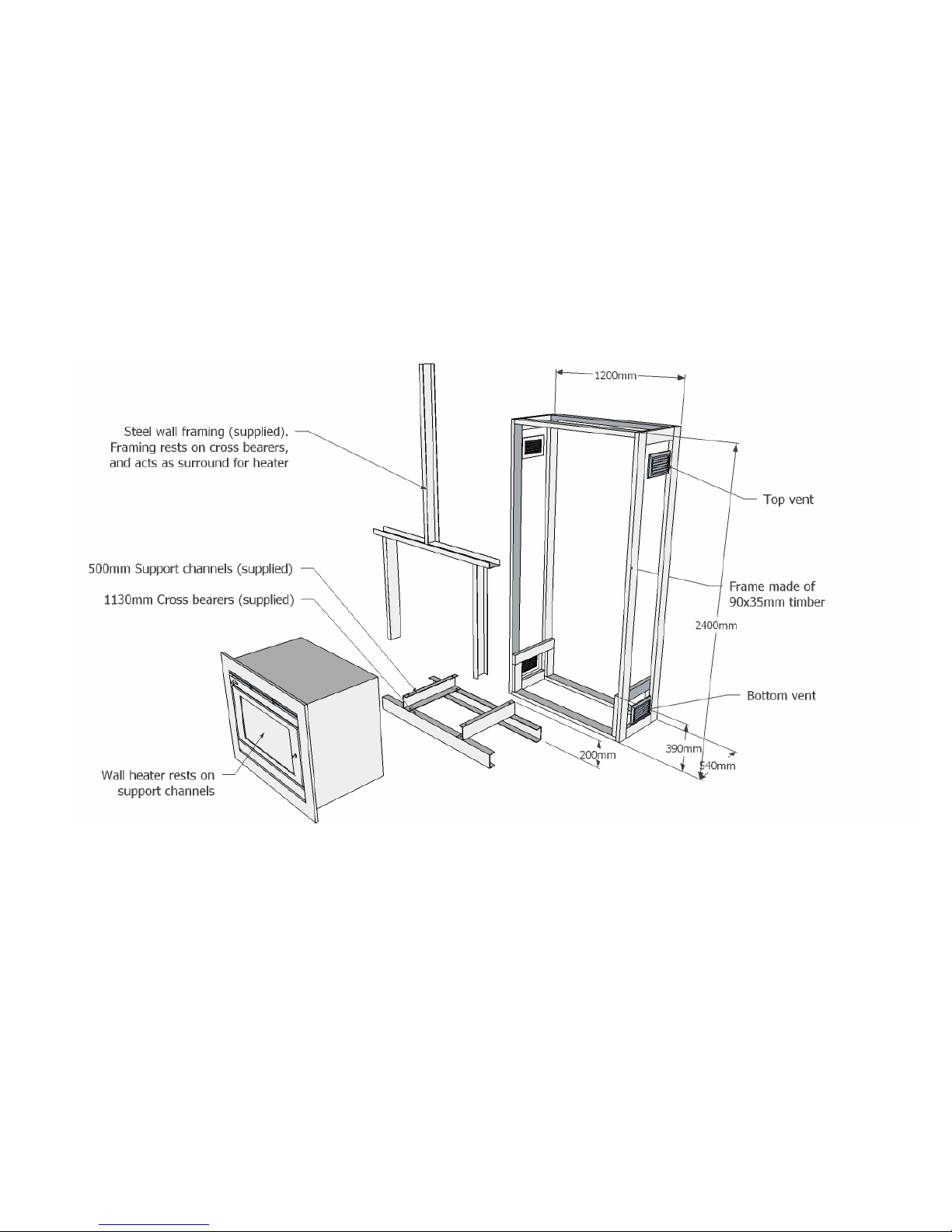
Steel Cross Bearers and Support Channels
Steel bearers are supplied with the heater to support it and provide adequate
ventilation underneath. The weight of the heater is taken on the two 1130mm
long by 100mm high cross bearers and these must be solidly supported with the
rear bearer 25mm clear of the rear wall.
The 500mm long by 100mm high support channels are bolted to the cross
bearers with the narrow flange to the top and having the top holes at 600 mm
centres (bolts supplied).
Wiring for Fan
Provide a wiring point in the cavity under the heater. If the cavity under the heater
will not be accessible once the heater is installed (such as through a removable
vent) then ensure an extension cord long enough to reach out of the front of the
opening is lying in the base of the cavity.
With the fan and outer trim removed slide the heater into the cavity and fix with
the supplied bolts to the support channels.
Access the power lead and plug the fan lead in to it pushing the lead into the wall
cavity under the heater. Fix the fan in place using the two 6mm screws at either
end.

8
Flue Requirements
Install a 150mm diameter double cased flue kit to comply with AS 2918. Fit an
additional 300 mm diameter outer casing from the heater to a minimum of 300
mm above the ceiling having bent tabs or spacers to ensure a 25 mm clearance
to the flue outer is maintained. A hole of 350 mm diameter is required in the
ceiling and a 25 mm clearance between any combustible material and the 300
mm outer casing. Refer to diagram below.
Fit the outer trim using the four 4mm screws. This is best achieved with the door
open.
The fire is now ready to use. Note the first few firings will cure the paint. Keep the
room well ventilated whilst this is happening as fumes are given off.

9
NECTRE 800 WALL HEATER – SUGGESTED FRAMING
The diagram on the next page shows a suggested wall enclosure for the Nectre
800 Wall Heater. Assuming a ceiling height of 2400mm, a timber frame has been
constructed using 90x35mm timber, 2400mm high, 1200mm wide, and 525mm
deep. With timber supports for the steel cross bearers at 390mm high, the base
of the heater will be 590mm above the floor.
A non-combustible material such as Versalux fibro cement sheeting is used on
the front wall, and standard gyprock or equivalent can be used on the side walls.
Vents have been positioned top and bottom on both side walls.
This construction complies with the minimum clearance requirements.
The height of the heater above the floor and/or the width of the enclosure may be
varied as long as it meets the clearances defined above.
10

11
DOOR HANDLE ADJUSTMENT
If leaking occurs the door gasket may be loose. It may be required to adjust the
door handle. If this occurs:
1) Wait until heater is cool.
2) Open door.
3) Undo lock nut on handle shaft and remove.
4) Remove locking latch and remove one washer.
5) Replace latch and lock nut.
6) Close and lock door.
7) If still not tight enough remove another washer or replace door seal.
NEW SEALS ARE AVAILABLE FROM YOUR DEALER
DOOR GLASS
Inspect door glass regularly for cracks and breaks. If a crack is found extinguish
fire immediately and replace glass. Contact your dealer for replacement glass.
If your glass becomes stained or smokey it can be cleaned with hot glass
cleaner or a damp cloth wiped in wood ashes. After using hot glass cleaner be
sure to clean glass completely.
DOOR GASKET
The door gasket should be checked for proper seal, wear or damage before
each winter. Door gaskets compress and it may be necessary to adjust or
tighten the door latch. *
Replacement door gaskets are available from your dealer.
*Further details in “Door Handle Adjustment”

12
FIREBRICKS
The firebricks are designed to fit in the base and along the rear and side walls of
the firebox. Please ensure the bricks are fitted before using the fire.
LIGHTING YOUR FIRE
1) Place firelighters and pieces of crumpled newspaper in firebox floor.
2) Cover the paper with small diameter split kindling.
3) Place 3 - 4 small pieces of firewood on top of the kindling.
4) Open air slide fully.
5) Light several parts of the newspapers.
6) Close the door to avoid smoke spillage. Do not close latch, this will allow
extra air into the firebox and helps create a draft.
After approximately 10 minutes:
7) Once firewood is fully ignited, CLOSE DOOR FULLY.
INITIAL OPERATION PERIOD
Operate your first few fires with the fan on high to allow the high temperature
paint to cure.
NOTE: For the first few fires the high temperature paint curing may cause an
odour. Ensure sufficient ventilation is supplied to allow dissipation of any smoke
and odour.
THIS ODOUR IS NORMAL

13
GENERAL OPERATION
Once the heater has been burning on high for approximately 20 to 30 minutes it
will have reached operating temperature. You may now slow the burn down by
adjusting the air slide into the closed position. Turn the fan on to the preferred
speed setting.
When adding wood, open the air slide fully, wait a few seconds, then open the
door slowly. After re-loading, leave air slide open, on high for 15 - 20 mins to
allow new fuel to catch freely and entirely.
Then re-adjust the air slide to desired setting for maximum efficiency. If the fire
is too small, refuelling first with kindling is advised.
OVERNIGHT BURN
An overnight burn can be achieved by following these steps an hour before
retiring:
1) Open air slide fully
2) Load with large pieces of dry wood
3) When all wood is burning, slowly move the air slide to low position.
4) Turn fan to OFF position.
NOTE: This procedure can be done at any time, for example, in the morning so
that the fire is still going later that day.

14
BAFFLE PLATE LOCATION
To clean your flue system the baffle plate will need to be removed.
Before continuing ensure the fire is completely extinguished.
1) Lift baffle up from the rear and slide forward out through the door. You
will need to lift the rear lip of the baffle plate over the front and rear
mounting rods.
2) After cleaning the flue system simply reverse the procedure and
replace your baffle.
3) Do not light the fire while the baffle is removed as this could cause a
serious house fire.

15
FAN SERVICE
To provide years of trouble free operation the fan motor bearings are factory
lubricated. However, damage can occur if dust or lint builds up in blades.
Therefore the fan assembly should be inspected and cleaned each year.
1. Turn off power and disconnect power lead.
2. Brush or vacuum fan blades taking care not to damage the blades.
3. Plug in power and turn on.
CLEANING THE FIREBOX
Ash should be cleared or removed when build up reaches the level of the door
opening.
To clean, use a metal fireplace shovel making sure all deposits are cold first.
Do not place hot ashes of coals in plastic rubbish bin.
CONTROLS
AIR SLIDE
Moving the air slide to the left enables maximum air into the firebox. Moving
air
slide to the right closes off air into the firebox, which slows the burn down.
FAN SWITCH
4 position switch with 3 speeds - High, Medium, Low.

16
TEN YEAR WARRANTY
:-
Pecan Engineering Pty Ltd warrants this stove to be able to operate under normal use
and service and within ten years from the date of the original purchase on the terms
herein shall repair or replace without cost to the original customer any part thereof which
shall be returned to our factory, transportation charges prepaid and which our inspection
shows would prevent operation. This warranty does not apply to the firebricks, brick
retainers, baffle plate, door seal, glass nor the discolouration of the surface or tarnishing
of knobs and handles all of which require normal service to maintain them. Electric fans
are only warranted against failure to operate for one year. Under the terms of this
warranty, Pecan Engineering Pty Ltd assumes no reponsibility for the labour costs
involved in removing or replacing the stove. Nor shall Pecan Engineering Pty Ltd be
liable for any injury, loss or damage (direct, indirect or consequential) arising out of the
use or inability to use the product, or its removal and replacement. All other stove
warranties, expressed or implied are excluded to the extent possible at law. Consumers
also have rights under relevant State and Commonwealth Laws.
The retailer does not have authority to alter this warranty.
PECAN ENGINEERING PTY LTD
13 Acorn Road Dry Creek S A 5094
Ph. (08) 8349 8332 Fax. (08) 8260 6643
- NOTES –
PURCHASED FROM:
DATE:
INSTALLED BY:
DATE:

17
REPLACEABLE COMPONENTS OF THE HEATER
1. Firebricks
800 Series 7 x 285mm x 175mm x 25mm
1 x 235mm x 85mm x 25mm
2. Ash Deflector
800 Series 595mm x 115mm x 5mm
3. Baffle Plate
800 Series 590mm x 288mm x 8mm
4. Door Rope
800 Series 1900mm x 16 mm Round
5. Glass Rope
800 Series 1840mm x 19mm x 3mm Flat Adhesive back
6. Brick Retainer Brackets
800 Series 2
7. Door Glass
800 Series 583mm x 303mm x 5mm pyroceramic
Other manuals for FS 800
2
Table of contents
Other Nectre Fireplaces Heater manuals


