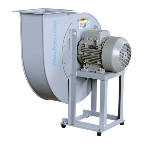
Nederman VAC 12 User manual

Vacuum unit
VAC 12/20
2016-02-08 144664(05)
Original instruction manual
EN INSTRUCTION MANUAL
Translation of original instruction manual
CS NÁVOD K OBSLUZE
DA BETJENINGSVEJLEDNING
DE BEDIENUNGSANLEITUNG
ES MANUAL DE INSTRUCCIONES
ET KASUTUSJUHEND
FI KÄYTTÖOHJEET
FR MANUEL D’INSTRUCTION
HU FELHASZNÁLÓI KÉZIKÖNYV
IT MANUALE D’ISTRUZIONE
NL HANDLEIDING
NO BRUKSANVISNING
PL INSTRUKCJAUŻYTKOWANIA
PT MANUAL DE INSTRUÇÕES
RU РУКОВОДСТВОПОЭКСПЛУАТАЦИИ
SV ANVÄNDARMANUAL
Instruction manual

VAC 12/20
2

VAC 12/20
3
Declaration of conformity................................................................................4
ECO design information......................................................................................7
Figures......................................................................................................................................................8
English..................................................................................................................................................15
Český...................................................................................................................................................... 35
Dansk...................................................................................................................................................... 57
Deutsch..............................................................................................................................................77
Español..............................................................................................................................................99
Eesti ..................................................................................................................................................... 121
Suomi.................................................................................................................................................142
Français.........................................................................................................................................162
Magyar.............................................................................................................................................184
Italiano............................................................................................................................................ 203
Nederlands.............................................................................................................................225
Norsk...................................................................................................................................................247
Polski...................................................................................................................................................267
Português..................................................................................................................................291
Русский........................................................................................................................................ 313
Svenska........................................................................................................................................ 335

VAC 12/20
4
Declaration of conformity
Declaraon of conformity
We, AB Ph. Nederman & Co., declare under our sole responsibility that the
Nederman product:
VAC 12/20 (Part No. **, and stated versions of **) to which this declaraon
relates, is in conformity with all the relevant provisions of the following
direcves and standards:
Direcves
2004/108/EC, 2006/42/EC, 2006/95/EC.
Standards
EN ISO 12100-1/2, EN 60204-1, EN 61000-6-2, EN 61000-6-4.
The name and signature at the end of this document, is the person responsible
for both the declaraon of conformity and the technical le.
English
EN
Konformitätserklärung
Wir, AB Ph. Nederman & Co., erklären in alleiniger Verantwortung, dass das
Nederman Produkt
VAC 12/20 (Art.-Nr. **, und bauartgleiche Versionen **), auf welches sich
diese Erklärung bezieht, mit allen einschlägigen Besmmungen der folgenden
Richtlinien und Normen übereinsmmt:
Richtlinien
2004/108/EC, 2006/42/EC, 2006/95/EC
Normen
EN ISO 12100-1/2, EN 60204-1, EN 61000-6-2, EN 61000-6-4.
Name und Unterschri am Dokumentende geben diejenige Person an, die für
die Konformitätserklärung und die technische Dokumentaon verantwortlich ist.
Deutsch
DE
Overensstemmelseserklæring
AB Ph. Nederman & Co. erklærer som eneansvarlige, at følgende produkt fra
Nederman:
VAC 12/20 (Arkel nr. **, og erklærede versioner af **), som denne erklæring
vedrører, er i overensstemmelse med alle de relevante bestemmelser i de
følgende direkver og standarder:
Direkver
2004/108/EC, 2006/42/EC, 2006/95/EC.
Standarder
EN ISO 12100-1/2, EN 60204-1, EN 61000-6-2, EN 61000-6-4.
Navnet og underskrien sidst i dee dokument lhører den person, der
er ansvarlig for såvel overensstemmelseserklæringen som den tekniske
dokumentaon.
Dansk
DA
Declaración de Conformidad
Nosotros, AB Ph. Nederman & Co., declaramos bajo nuestra única
responsabilidad que el producto Nederman:
El producto, VAC 12/20 (Ref. nº **, y las versiones basadas **),, al que hace
referencia esta declaración, cumple con todas las disposiciones aplicables de las
Direcvas y normas que se indican a connuación:
Direcvas
2004/108/EC, 2006/42/EC, 2006/95/EC.
Normas
EN ISO 12100-1/2, EN 60204-1, EN 61000-6-2, EN 61000-6-4.
El nombre y rma que guran al nal de este documento corresponden a la
persona responsable, tanto de la declaración como de la cha técnica.
Español
ES
Prohlášení o shodě
My, společnost AB Ph. Nederman & Co., prohlašujeme na svou zodpovědnost, že
výrobek Nederman:
VAC 12/20 (díl č. **, a uvedla, verze **), ke kterému se toto prohlášení vztahuje,
je v souladu se všemi příslušnými ustanoveními následujících směrnic a norem:
Směrnice
2004/108/EC, 2006/42/EC, 2006/95/EC.
Normy
EN ISO 12100-1/2, EN 60204-1, EN 61000-6-2, EN 61000-6-4.
Na konci tohoto dokumentu je jméno a podpis osoby zodpovědné za prohlášení
o shodě a soubor technické dokumentace.
Češna
CS
Vastavusdeklaratsioon
Meie, AB Ph. Nederman & Co., kinnitame ja kanname ainuisikuliselt vastutust
selle eest, et eevõe Nederman toode:
VAC 12/20 (arkkel nr **, ja märkis versioonid **), mida käesolev deklaratsioon
puudutab, vastab kõigi järgnevate direkivide ja standardite kohaldatavatele
sätetele:
Direkivid
2004/108/EC, 2006/42/EC, 2006/95/EC.
Standardid
EN ISO 12100-1/2, EN 60204-1, EN 61000-6-2, EN 61000-6-4.
Dokumendi lõpus on nii vastavusdeklaratsiooni kui ka tehnilise toimiku eest
vastutava isiku nimi ja allkiri.
Ees
ET

VAC 12/20
5
Dichiarazione di conformità
AB Ph. Nederman & Co., dichiara soo la propria esclusiva responsabilità che il
prodoo Nederman:
VAC 12/20 (Art. N. **, e le versioni di deo **) al quale è relava la presente
dichiarazione, è conforme alle disposizioni delle seguen direve e normave:
Direve
2004/108/EC, 2006/42/EC, 2006/95/EC.
Normave
EN ISO 12100-1/2, EN 60204-1, EN 61000-6-2, EN 61000-6-4.
Il nome e la rma in calce al presente documento appartengono al responsabile
della dichiarazione di conformità e della documentazione tecnica.
Italiano
IT
Megfelelőségi nyilatkozat
Az AB Ph. Nederman & Co. vállalat teljes felelőssége tudatában kijelen, hogy
a(z)
VAC 12/20 (cikkszám: **, és módosíto verziói **) termék, amelyre ez a
nyilatkozat vonatkozik, megfelel az alábbi irányelveknek és szabványoknak:
Irányelvek:
2004/108/EC, 2006/42/EC, 2006/95/EC.
Szabványok:
EN ISO 12100-1/2, EN 60204-1, EN 61000-6-2, EN 61000-6-4.
A dokumentum végén található név és aláírás a megfelelőségi nyilatkozatért és a
műszaki dokumentációért felelős személy neve és aláírása.
Magyar
HU
Declaração de conformidade
Nós, AB Ph. Nederman & Co., declaramos sob nossa inteira responsabilidade
que o produto Nederman:
VAC 12/20 (Argo nº ** e as versões do indicado **), ao qual esta declaração se
refere, está em conformidade com todas as disposições relevantes das seguintes
direvas e normas:
Direcvas
2004/108/EC, 2006/42/EC, 2006/95/EC.
Normas
EN ISO 12100-1/2, EN 60204-1, EN 61000-6-2, EN 61000-6-4.
O nome e a assinatura no nal deste documento são os da pessoa responsável
pela declaração de conformidade e pelo cheiro técnico.
Português
PT
Deklaracja zgodności
Firma AB Ph. Nederman & Co. niniejszym deklaruje z pełną odpowiedzialnością,
że oferowany przez nią produkt VAC 12/20 (nr części ** i oznaczenie wersji **),
do którego odnosi się ta deklaracja, spełnia wszystkie odpowiednie wymagania
poniższych dyrektyw i norm:
Dyrektywy
2004/108/EC, 2006/42/EC, 2006/95/EC.
Normy
EN ISO 12100-1/2, EN 60204-1, EN 61000-6-2, EN 61000-6-4.
Na końcu niniejszego dokumentu znajdują się imię, nazwisko oraz podpis osoby
odpowiedzialnej za deklarację zgodności oraz dokumentację techniczną.
Polski
PL
Conformiteitsverklaring
Wij, AB Ph. Nederman & Co, verklaren in uitsluitende aansprakelijkheid dat het
product van Nederman:
VAC 12/20 (Arkelnr. **, en verklaarde versies van **), waarop deze verklaring
van toepassing is, in overeenstemming is met alle relevante voorschrien van de
volgende richtlijnen en normen:
Richtlijnen
2004/108/EC, 2006/42/EC, 2006/95/EC.
Normen
EEN ISO 12100-1/2, EN 60204-1, EN 61000-6-2, EN 61000-6-4.
Naam en handtekening onder dit document zijn van degene die
verantwoordelijk is voor zowel de Verklaring van Overeenstemming als het
technische document.
Nederlands
NL
Samsvarserklæring
Vi, AB Ph. Nederman & Co, erklærer på eget ansvar at Nedermans produkt:
VAC 12/20 (Del nr. **, og ualte versjoner av **) som denne erklæringen gjelder
for, er i overensstemmelse med følgende direkver og standarder:
Direkver
2004/108/EC, 2006/42/EC, 2006/95/EC.
Standarder
EN ISO 12100-1/2, EN 60204-1, EN 61000-6-2, EN 61000-6-4.
Navnet og signaturen l slu i dee dokumentet lhører vedkommende som er
ansvarlig for både samsvarserklæringen og den tekniske len.
Norsk
NO
Déclaraon de conformité
Nous, AB Ph. Nederman & Co., déclarons sous notre seule responsabilité que le
produit Nederman :
VAC 12/20 (Réf. **, et les modèles basés sur les réf. **) auquel fait référence la
présente déclaraon est en conformité avec toutes les disposions applicables
des direcves et normes suivantes :
Direcves
2004/108/EC, 2006/42/EC, 2006/95/EC.
Normes
EN ISO 12100-1/2, EN 60204-1, EN 61000-6-2, EN 61000-6-4.
Le nom et la signature en bas de ce document apparennent à la personne
responsable de la déclaraon de conformité et du chier technique.
Français
FR
Vaamustenmukaisuusvakuutus
Me, AB Ph. Nederman & Co., vakuutamme yksinomaan omalla vastuullamme,
eä Nederman-tuote
VAC 12/20 (tuotenro **, ja totesi versioita **), jota tämä vakuutus koskee, on
seuraavien direkivien ja standardien kaikkien asianmukaisten säännösten
mukainen:
Direkivit:
2004/108/EC, 2006/42/EC, 2006/95/EC.
Standardit
EN ISO 12100-1/2, EN 60204-1, EN 61000-6-2, EN 61000-6-4.
Tämä asiakirjan lopussa oleva nimi ja allekirjoitus ovat henkilön, joka vastaa sekä
vaamuksenmukaisuusvakuutuksesta eä teknisestä edostosta.
Suomi
FI
VAC 12/20
6
Декларация о соответствии
Компания AB Ph. Nederman & Co. со всей ответственностью заявляет, что
оборудование Nederman:
VAC 12/20 (№ по каталогу **, и заявил, версии **), к которому относится
данная декларация, соответствует всем требуемым положениям
следующих директив и стандартов.
Директивы
2004/108/EC, 2006/42/EC, 2006/95/EC.
Стандарты
EN ISO 12100-1/2, EN 60204-1, EN 61000-6-2, EN 61000-6-4.
Сотрудник, поставивший свою подпись под данным документом, отвечает
как за соблюдение декларации о соответствии, так и за достоверность
технических данных.
Русский
RU
Försäkran om överensstämmelse
Vi, AB Ph. Nederman & Co., försäkrar under eget ansvar a Nederman-
produkten:
VAC 12/20 (arkelnr **, och fastställda versioner av **.), som denna försäkran
avser, överensstämmer med alla llämpliga bestämmelser i följande direkv och
standarder:
Direkv
2004/108/EC, 2006/42/EC, 2006/95/EC.
Standarder
EN ISO 12100-1/2, EN 60204-1, EN 61000-6-2, EN 61000-6-4.
Namn och namnteckningen i slutet av dea dokument är den person som
ansvarar både för försäkran om överensstämmelse och för den tekniska
dokumentaonen.
Svenska
SV
AB Ph. Nederman & Co.
P.O. Box 602
SE-251 06 Helsingborg
Sweden
Lars Nagy
Manager Product Centre
2016-02-08
**
40103101, 40103110, 40103120, 40103121, 40103130, 40103131, 40103141, 40103151, 40103161, 40103221, 40103230, 40103231, 40103240, 40103251,
40103261, 40103271, 40103281, 40103291, 40103351, 40103360, 40103361, 40103370, 40103371, 40103381, 40103391, 40103401, 40103411, 40103461,
40103470, 40103481, 40103490, 40103491, 40103501, 40103511, 40103521, 40103531, 40103550, 40103171, 41001990

VAC 12/20
7
#Product information requirements VAC 12-3000 VAC 20-1500 VAC 20-2500 VAC 20-3000 VAC 20-4000
1. Overall eciency (%). 52,4 49,1 47,9 47,3 45,7
2. Measurement category (A-D).(1) DDDDD
3. Eciency category (Total). Total Total Total Total Total
4. Eciency grade at optimum energy eciency point. 61 61 61 61 61
5. Did fan eciency calculation use an integrated VSD. No No No No No
6. Year of manufacture. See the product’s nameplate.
7a. Manufacturer’s name. See the product’s nameplate.
7b. Commercial registration number. See the product’s nameplate.
7c. Place of manufacturer. See the product’s nameplate.
8Model number. See the product’s nameplate.
9a Rated motor power input (kW). See section 4.1 Technical data.
9b Flow rate at optimum energy eciency (m3/h). 2800 2000 2500 3000 3000
9c. Pressure at optimum energy eciency (Pa). 12400 19500 20000 19500 19900
10. Rotations per minute at the optimum energy eciency
point (rpm). 4660 4250 4480 4480 4470
11. Specic ratio.(2) 1,14 1,24 1,25 1,24 1,24
12. Fan disassembly, recycling and disposal at end-of-
life: See the sections for maintenance and recycling.
13. To minimize environmental impact and ensure optimal
life expectancy for the fan: Carefully follow the installation, use and maintenance instructions for the fan.
14. Additional items.(3)
1. According to Comission regulation (EU) No 327/2011 implementing Directive 2009/125/EC.
2. The stagnation pressure measured at the fan outlet divided by the stagnation pressure at the fan inlet at the optimal energy eciency point of
the fan.
3. Additional items used when determining the fan energy eciency that are not described in the measurement category and not supplied with
the fan.
ECO design information

VAC 12/20
8
Figures
4, 5, 6 7
8
9
10
3
2
1
1 2
3
4
5
6
7
8
1
2
3
1
1
2
4
3

VAC 12/20
9
1
2
346
5
7
8
11
12
13
14
9
10
15
16
Start and control unit
VAC 12
VAC 20
24VDC
30 31
30 31
V1 TVS 200
V1 TVS 200
V2 TAV 50 MV
TS
79°
30 31
Start and control unit
VAC 12
VAC 20
VAC 20
RTS
110°
RTS
110°
32
Compressed
Air Switch
(option)
33
32 33 34 35
34 35
6
Start and control unit
8
7
5

VAC 12/20
10
1214 mm
47.80"C-C
770 mm
30.31"C-C
(4x) 13 mm
1/2"
1256 mm
49.45"
2372 mm
93.39"
587 mm
23.11"(VAC 20)
121 mm
4.76"
200 mm
7.87"
1510 mm
59.45"
1070 mm
42.13"
204 mm
8.01"
415 mm
16.34"
488 mm
19.21"(VAC 20)
543 mm
21.38"(VAC 12)
645 mm
25.39"(VAC 12)
2450 mm
96.46"
VAC 12-3000
VAC 20-3000
VAC 20-4000
250 mm
9.84"
200 mm
7.87"
VAC 20-1500
VAC 20-2500
Ø
Ø
Ø
Ø
9

VAC 12/20
11
~35 ml ATF
70-85 mm
X
U1
V1
W1
W2
U2
V2
X
10
11
12
14
13
10mm (0.39")
15

VAC 12/20
12
16
1
67
5
4
3
2
17
18

VAC 12/20
13
19
Min Max
E1M
M
E1
S2S1
S1
L1
S2
I>
I<
High Vacuum St art er
L1
A2A2
A1 A1
MaxMin
R1
Max
Min
31212
2
1
11
1414
11
A
BC
L1
N
25
24
A1
A2
23(+)
22(-)
R1
Val ve
motor
20

VAC 12/20
14
R1
E3E1 E2
El
A214 12
M11A1
E3E1 E2
El
A214 12
M11A1
MAX
E-nummer
Year of manuf. XXXX
MIN
%
Hyst
Ie%
T2
T1
R
50
30
40
10
20
0
100
Uh
60
90
80
70
50
20 10
30
40
0
%
Hyst
Ie%
T2
T1
R
50
30
40
10
20
0
100
Uh
60
90
80
70
50
20 10
30
40
0
MIN MAX
!!
21

VAC 12/20
15
EN
1 Preface ....................................................................................................................................................17
2 Hazard notices.................................................................................................................................17
3 Safety ........................................................................................................................................................17
4 Description...........................................................................................................................................18
4.1 Technical data ...........................................................................................................................18
4.2 Function .........................................................................................................................................19
4.2.1 Optional: Anti surge control ..............................................................................................19
5 Main components.........................................................................................................................20
5.1 Overview .......................................................................................................................................20
5.2 Connections................................................................................................................................20
5.3 Start-up valve.............................................................................................................................21
5.4 Flow restrictor FR 160..........................................................................................................21
5.5 VAC 20: Temperature control..........................................................................................22
5.6 VAC 20: Bearing temperature switches...................................................................22
5.7 Optional: Compressed air switch.................................................................................22
5.8 Optional: Anti surge control..............................................................................................22
6 Before installation.........................................................................................................................23
6.1 Delivery check...........................................................................................................................23
6.2 Installation requirements....................................................................................................23
6.2.1 Location...................................................................................................................................23
6.2.2 Foundation .............................................................................................................................23
7 Installation.............................................................................................................................................24
7.1 Installing VAC 12/20 ..............................................................................................................24
7.1.1 Indoor installation.................................................................................................................24
7.1.2 Outdoor installation.............................................................................................................24
7.1.3 Compressed air installation..............................................................................................25
7.2 Optional: Installing Anti surge control.......................................................................25
8 Using VAC 12/20............................................................................................................................25
8.1 Before start-up ..........................................................................................................................25
8.2 Initial start-up..............................................................................................................................26
8.2.1 Checking the direction of rotation...................................................................................26
8.2.2 Checking the Y/D time setting..........................................................................................26
8.2.3 Initial start-up with pilot signal cable..............................................................................26
8.2.4 Adjusting the Anti surge control ......................................................................................27
9 Maintenance.......................................................................................................................................28
9.1 General inspection.................................................................................................................28
9.2 Belt transmission.....................................................................................................................28
9.3 VAC 20: Temperature control..........................................................................................29
9.4 Start-up valve.............................................................................................................................29
Figures......................................................................................................................................................... 8
Table of contents
English
Instruction manual
Vacuum unit
VAC 12/20

VAC 12/20EN
16
9.5 Flow restrictor FR 160.............................................................................................29
9.5.1 Adjusting FR 160.....................................................................................................29
9.5.2 Flow restrictor oil..................................................................................................... 30
9.6 Fan bearings temperature.................................................................................... 30
9.7 Fan bearings..................................................................................................................30
9.8 Motor bearings.............................................................................................................30
9.9 Optional: Anti surge control................................................................................. 31
9.10 Spare parts.....................................................................................................................31
10 Recycling................................................................................................................................... 31
11 Acronyms and abbreviations............................................................................... 31

VAC 12/20
17
EN
1 Preface
This manual is a guide for the correct installation, use and maintenance of this
product. Study it carefully before starting to use the product or before carrying
out any maintenance. Keep the manual where it is always close at hand.
Replace it immediately if lost.
NOTE! Read ‘3 Safety’!
This product has been designed to meet the requirements of the relevant EC
directives. To maintain this status, all installation, repair and maintenance
work must be carried out by qualied personnel using only Nederman original
spare parts. Contact your nearest authorized distributor or Nederman for
advice on technical service or if you require help with spare parts.
Many hours have been spent on the design and production of this product in
order to make it as efcient and safe as possible. Accidents that occur despite
this are usually caused by individuals. A safety-conscious person and a well-
maintained product make a safe and effective combination.
We continuously improve our products and their efciency through the
introduction of design modications. We reserve the right to do this without
introducing these improvements on previously supplied products. We also
reserve the right, without previous notice, to modify data and equipment, as
well as operating and maintenance instructions.
2 Hazard notices
This document contains hazard information which must be read by all users.
The hazard information is presented as a warning, caution or note as follows:
WARNING! Type of injury
Warnings indicate a potential hazard to the health and safety of users. They
clearly state the nature of the hazard and how to avoid it. They appear at their
points of application in this document. They look like this notice, but with
different texts.
CAUTION! Type of risk.
Cautions indicate a potential hazard to the physical integrity of the equipment,
but not a danger to personnel. They clearly state the nature of the hazard and
how to avoid it. They appear at their points of application in this document.
They look like this notice, but with different texts.
NOTE! Notes contain other information which the user should be especially
aware of.
3 Safety
NOTE! For reasons of safety, this manual must be studied before using the
product for the rst time.
Never start the unit before installation is complete.
WARNING! Risk of eye injury.
Always stop the unit before looking into the outlet. The fan rotates at high
speed and even small particles of dust could severely damage the eyes.

VAC 12/20EN
18
WARNING! Risk of cutting injury.
Ensure the dust collector is attached to the unit’s inlet and the silencer attached
to the outlet. Suction at the inlet is very powerful and any contact with the fan
wheel could result in severe injury.
WARNING! Risk of personal injury.
The belt guard must always be tted except during maintenance work on the
transmission. Maintenance must be undertaken by qualied personnel. Ret
the guard when the work is nished. The Figures in this manual without the
guard in place are for illustration purposes only and do not imply that the unit
ever is to be run without the guard.
WARNING! Risk of electric shock.
The thermal switches in the unit must always be enabled. Switch off and lock
the mains maintenance switch or remove the mains fuses before starting the
inspection.
CAUTION! Risk of equipment damage.
The dust collector must be positioned before the vacuum unit. The dust
collector must be designed and maintained to prevent coarse particles and dust
from being sucked into the fan. The ltering of ne dust must be sufcient
to prevent undue wear to the fan. The unit must be stopped immediately for
inspection by suitably qualied personnel if the fan rotates unevenly, or if
damage to the fan or its bearings is suspected.
4 Description
4.1 Technical data
Table 4-1: Technical data
VAC 12-3000 20-1500 20-2500 20-3000 20-4000
Operating temperature -20 °C to +40 °C (60 °F to 104 °F)
Dimensions See Figure 9
Inlet mm(in) Ø 200 (7.78")
Outlet mm (in) Ø 250
(9.84") Ø 200
(7.78") Ø 200
(7.78") Ø 250
(9.84") Ø 250
(9.84")
Weight without motor, kg (lb) 261 (575) 370 (815) 370 (805) 370 (805) 370 (805)
Total weight*, Europe and Asia, kg (lb) 412 (908) 573 (1263) 616 (1358) 626 (1380) 698 (1539)
Total weight*, North America, kg (lb) 397 (875) 546 (1204) 614 (1354) 635 (1400) 786 (1733)
Total weight*, Brazil, kg (lb) 396 (873) 505 (1113) 602 (1327) 628 (1385) 663 (1462)
Maximum vacuum, kPa (in.W.G.) 13.3 (53) 20.1 (81) 21.5 (86) 21.5 (86) 22 (88)
Specied capacity, m3/h /kPa (cfm/
in.W.G.)
3000/12
(1766/48) 1500/20
(883/80) 2500/20
(1471/80) 3000/19
(1766/76) 4000/16.5
(2354/66)
Maximum ow at rated motor power
m3/h (cfm) 3500
(2060) 2300
(1354) 3000
(1766) 3900
(2295) 5000
(2943)
Noise level
ISO 11201 dB(A) 75.4 71 74.5 74.5 74.5
Noise level**
ISO 11201 dB(A) 68.6 66 67 68 68
Motor data See motor label
Motor power, kW (HP) 18.5 (25) 22 (30) 30 (40) 37 (50) 45 (60)
Control voltage 24 V DC ± 10% (solenoid for 24 V AC enclosed)
* Motor weight included.
** With optional silencer.

VAC 12/20
19
EN
VAC 12-3000 20-1500 20-2500 20-3000 20-4000
Compressed air quality Clean dry, ISO 8573-1 class 5
Required air pressure 6–8 bar (87–116 PSI)
Maximum air consumption intermittent 70 N-Litres/min (2.5 cfm)
Material description Powder coated steel, copper, stone wool insulation.
Material recycling Approximately 95% to 97% of the weight.
FR 160 spring, see Figure 3. - 1 - six turns
Ø 2 mm
wire
2 - four
turns Ø 2
mm wire
3 - six turns
Ø 2,5 mm
wire
-
* Motor weight included.
** With optional silencer.
4.2 Function
VAC 12/20 is a series of vacuum units that operate for an air ow up to the
level specied in ‘Table 4-1: Technical data’. VAC 12 operates at 12 kPa (48"
W.G.) vacuum and VAC 20 operates at 20 kPa (80" W.G.) vacuum.
Units are delivered with different capacities, voltages, and frequencies. The
motor is a 3-phase asynchronous motor. The motor power matches the unit’s
capacity. The vacuum source is a belt-driven high-pressure fan. The power
consumption of the fan increases with increasing air ow. It is necessary
to minimise the power requirement during Y/D - starting. This is done by
restricting the air ow while the motor is operating in Y-mode.
VAC 12/20 units have a start-up valve at the fan inlet. The valve is, apart from
a small leakage ow, closed when the unit is at stand still and during start up
in Y-mode. The valve will open when the motor switches over to full power in
D-mode. The valve is controlled from the unit’s start and control unit.
See Section ‘5.6 VAC 20: Bearing temperature switches’ regarding
the bearing overheating cut-out on VAC 20. See
Section ‘5.7 Optional: Compressed air switch’ regarding compressed air switch.
4.2.1 Optional: Anti surge control
A high pressure centrifugal fan operating with too small an air ow, will
run in a surge. This means that the operation is not stable. A characteristic
‘pumping’ or ‘breathing’ sound can be heard and the air stream at the fan outlet
will be uneven. The vacuum generation is unstable and this can, under certain
circumstances, cause the ducting to move in rhythm with the pumping.
The motor current is closely related to the air ow through the fan. By
monitoring the current by means of a current transformer in the start and
control unit, it is possible to determine whether the ow is small enough to
cause a surge. If this is the case, a valve inside the vacuum unit will gradually
open to let some more air into the fan.
Figure 8 shows the wiring between the high vacuum start and control unit
and Anti surge control. Figure 17 is the electrical circuit diagram. The current
transformer monitors the motor current for phase L1. The signal is hard-wired
to the relay box where it passes through two current sensing relays called
MAX and MIN. See the left part of Figure 20.
The MIN relay will be activated if the current is smaller than a set minimum
value (opening the valve).

VAC 12/20EN
20
The MAX relay is activated if the current is higher than a set maximum
value (closing the valve). If the current is within the ‘dead band’ between the
minimum and maximum settings, no relay is activated and the valve is static.
5 Main components
5.1 Overview
Figure 1 shows the main components of the VAC 12/20 unit. These are as
follows:
1. Acoustic enclosure.
2. Motor.
3. VAC 12: High pressure fan.
VAC 20: 2-stage high pressure fan.
4. Start-up valve. VAC 12 has model TVS 200. VAC 20 has model SUV 200
which also serves as a back ush valve. 24 V DC is supplied as standard
but a solenoid for 24 V AC is also enclosed.
5. VAC 20: Temperature control valve. 24 V AC/DC is supplied as standard.
The valve may be replaced by the anti surge valve, Item 6.
6. VAC 20: Anti surge valve. Optional replacement for the temperature
control valve, Item 5.
7. VAC 20-1500/2500/3000: Flow restrictor FR 160, see also Figure 4.
8. VAC 20: Thermal switch for fan housing. Used with temperature control
valve only.
9. VAC 20: Manual reset thermal switch for the fan bearings. See also
Figure 13 for details.
10. Belt transmission.
The optional inlet silencer is shown in Figure 2.
1. Optional: Inlet silencer for extra low noise levels indoors.
5.2 Connections
Figure 5 is a schematic diagram of the normal connections to a VAC unit. For
electrical connections, see the start and control unit’s manual and also Figure
6–8. Connections may vary depending on the options chosen. Connecting
material such as cables are not included with the unit. See the dust collector
manual for information about dust collector connections.
Most failures are result from faults in the electrical equipment or connections.
The motor overload relay must be of the ‘heavy start type’ as some units are
heavy to start. Otherwise the motor overload may trip because of the high
current and the long time spent in the Y-mode.
NOTE! Electrical installation must be made by a qualied electrician.
NOTE! National and local electric regulations must be followed.
Start and control units from Nederman have terminals for easy connection of
all control cables. If other equipment is used, this equipment must be similarly
equipped and connected for the guarantee of the VAC 12/20 unit to be valid.
This manual suits for next models
1
Table of contents
Languages:
Other Nederman Fan manuals

Nederman
Nederman N3 User manual

Nederman
Nederman N Series User manual

Nederman
Nederman N10 User manual

Nederman
Nederman 865 series User manual

Nederman
Nederman NCF 30/15 User manual

Nederman
Nederman NCF 30/15 User manual

Nederman
Nederman N3 User manual

Nederman
Nederman N16 User manual

Nederman
Nederman 865 series User manual

Nederman
Nederman N Series User manual