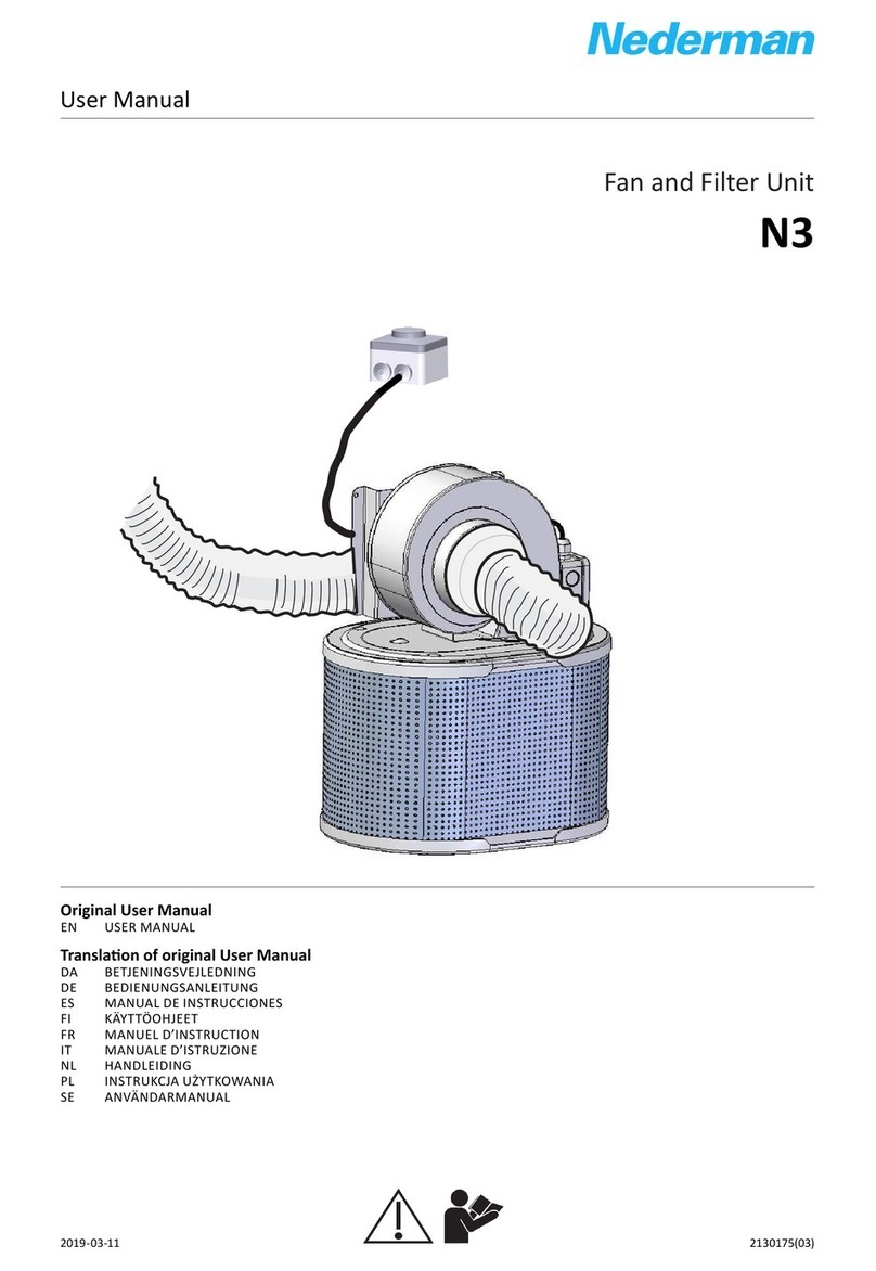
Nederman NCF Series User manual

Central Fan
NCF
2130187(01)2018-12-07
Original instrucon manual
EN INSTRUCTION MANUAL
Instruconmanual

NCF
2
Declaraon of conformity ................................................................................................ 3
Figures .................................................................................................................................................................. 4
English ................................................................................................................................................................... 9

NCF
3
Declaraon of conformity
We, AB Ph. Nederman & Co., declare under our sole responsibility that the
Nederman product:
NCF (Part No. **, and stated versions of **) to which this declaraon relates,
is in conformity with all the relevant provisions of the following direcves and
standards:
Direcves
2006/42/EC, 2014/30/EU, 2009/125/CE (Reg.CE/327/2011).
The name and signature at the end of this document, is the person responsible
for both the declaraon of conformity and the technical le.
English
EN
**
14550128, 14550228, 14550328, 14550428, 14550528, 14550628, 14550728, 14550828, 14550928, 14551028, 14551128, 14551228, 14551328, 14551428,
14551528, 14552128, 14552228, 14552328, 14552428, 14552528, 14552628
AB Ph. Nederman & Co.
P.O. Box 602
SE-251 06 Helsingborg
Sweden
Frank Christensen
VP Operaons EMEA
2018-12-13

NCF
4
W2 U2 V2
U1 V1 W1
L1 L2 L3
U2
W2 V2
YY connecon 230 V ∆∆ connecon 230 VY connecon 460 V ∆connecon 460 V
U1 V1 V5U5 W1 W5
W2 U2 V2
U1 V1 W1
L1 L2 L3
U1 V1 W1
W2 U2 U5W5 V2 V5
W2 U2 V2
U1 V1 W1
L1 L2 L3
U1 V1 W1
W2 U2 U5W5 V2 V5
W2 U2 V2
U1 V1 W1
L1 L2 L3
U1 V1 W1
U5 V5 U2W2 V2 W5
Figures
1
2
Delta connecon
3
Star connecon
4

NCF
5
MOUNTING INSTRUCTION
Vibraon absorbers
5
Clockwise
rotaon RD
RD0 - StandardRD90
RD30 RD60 RD120 RD150 RD270 RD300 RD330
OUTLET DIRECTIONS
Can be posioned aer order
Clockwise
rotaon RD
RD0 - Standard RD45 RD90 RD135 RD270 RD315
Outlet direcons for all NCF fans except NCF 30/15.
Outlet direcons only for NCF 30/15.
6

NCF
6
Example of lifting NCF fans.
7
Minimum installaon distances with inlet duct.
8

NCF
7
10 mm Max
40 mm Max 10° Max
Theorecal Parallel misalignment Axial compression Angular misalignment
9
Minimum installaon distances with open inlet.
10

NCF
8
OUTDOOR INSTALLATIONS
Leave a bend on the cable to prevent
water from entering the motor
11

NCF
9
EN
Table of contents
English
Instrucon manual
1 Preface ..............................................................................................................................................................................10
2 Safety .................................................................................................................................................................................10
2.1 General ..............................................................................................................................................................10
2.2 Mechanical characteriscs risks ..........................................................................................................11
2.3 Environmental risks ....................................................................................................................................11
2.4 Vibraon risks ................................................................................................................................................12
2.5 Operang speed risks................................................................................................................................13
2.6 Noise emission risks ...................................................................................................................................14
3 Descripon .....................................................................................................................................................................14
3.1 Intended use ..................................................................................................................................................14
3.2 Prohibited uses .............................................................................................................................................15
3.3 Life cycle of fan .............................................................................................................................................15
3.4 Technical specicaons ............................................................................................................................15
3.4.1 Technical data 50 Hz fans (metric) .........................................................................................15
3.4.2 Technical data 60 Hz fans (metric) .........................................................................................16
3.4.3 Technical data 60 Hz fans, 380 V (metric) ..........................................................................17
3.4.4 Technical data 60 Hz fans (imperial) .....................................................................................17
4 Installaon ......................................................................................................................................................................18
4.1 Delivery check ...............................................................................................................................................19
4.2 General informaon ..................................................................................................................................19
4.2.1 Fan orientaon .................................................................................................................................19
4.2.2 Standard fan outlet posion for NCF fans .........................................................................19
4.3 Installaon types .........................................................................................................................................20
4.4 Transport ..........................................................................................................................................................21
4.4.1 Transport and liing ......................................................................................................................21
4.4.2 Liing NCF fans .................................................................................................................................21
4.4.3 Storage in a warehouse ...............................................................................................................22
4.5 Mounng .........................................................................................................................................................22
4.5.1 Outdoor installaon ......................................................................................................................22
4.5.2 Minimum distances between components .....................................................................22
4.5.3 Electrical connecons ...................................................................................................................23
4.5.4 Motor connecons .........................................................................................................................23
4.6 Connecon to ducts ...................................................................................................................................23
4.7 Checks to be made before and aer starng ..............................................................................23
4.7.1 Preliminary checks..........................................................................................................................23
4.7.2 Checks to be carried out with the fan running ...............................................................24
4.7.3 Visual checks on guards ...............................................................................................................24
5 Use ......................................................................................................................................................................................25
6 Maintenance .................................................................................................................................................................25
6.1 Visual inspecons on blades and casing.........................................................................................27
6.2 Checking and cleaning parts in contact with the uid ............................................................27
6.3 Disassembly ....................................................................................................................................................28
6.3.1 Intake nozzles ....................................................................................................................................28
6.3.2 Housing .................................................................................................................................................28
6.3.3 Impeller ................................................................................................................................................28
6.4 Flexible an-vibraon joints between the fan and ducng .................................................28
6.5 Technical enclosures ..................................................................................................................................28
6.6 Spare parts ......................................................................................................................................................29
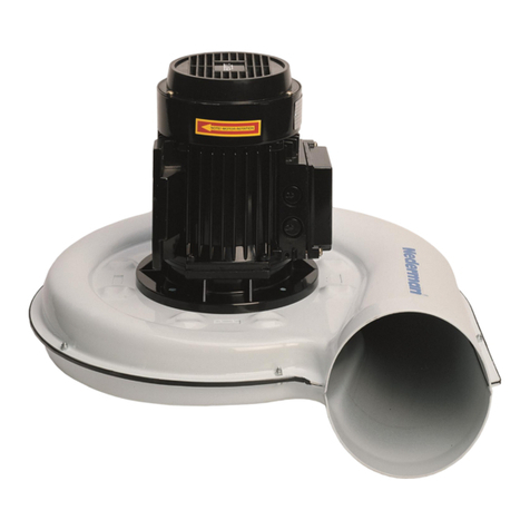
NCFEN
10
1 Preface
Read this manual carefully before installaon, use and service of this product. Replace
the manual immediately if lost. Nederman reserves the right, without previous noce, to
modify and improve its products including documentaon.
This product is designed to meet the requirements of relevant EU direcves. To maintain
this status, all installaon, maintenance and repair is to be done by qualied personnel
using only Nederman original spare parts and accessories. Contact the nearest authorized
distributor or Nederman for advice on technical service and obtaining spare parts. If there
are any damaged or missing parts when the product is delivered, nofy the carrier and the
local Nederman representave immediately.
2 Safety
This document contains important informaon that is presented either as a warning,
cauon or note:
WARNING! Risk of personal injury.
Warnings indicate a potenal hazard to the health and safety of personnel, and how that
hazard may be avoided.
CAUTION! Risk of equipment damage.
Cauons indicate a potenal hazard to the product but not to personnel, and how that
hazard may be avoided.
NOTE! Notes contain other informaon that is important for personnel.
2.1 General
Table 2-1: Explanaon of sign and scker symbols used on the product.
Sign Descripon
Do not remove the guards.
Indicates a point that is to be used for liing and moving the fan.
6.7 Recycling ...........................................................................................................................................................29
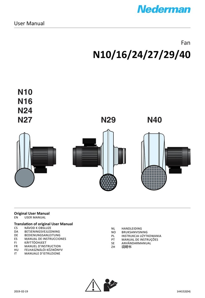
7 Troubleshoong ...........................................................................................................................................................29

NCF
11
EN
Sign Descripon
Generic hazard warning.
Posioned near the condensaon discharge plug (if present), to warn of the possible
presence of hazardous substances and/or substances at a high temperature.
2.2 Mechanical characteriscs risks
The following is a list of specic hazards related to the fan’s mechanical characteriscs.
WARNING! Risk of personal injury.
A person may receive injuries as a result of:
• Being dragged between a moving part and a xed part, for example a impeller and the
casing or some other xed part of the fan.
• Being dragged into the fan through the air intake, with consequent contact with the
sha or impeller.
• Contact with a moving part, such as the impeller.
• Ejecon from the fan exit of fragments deriving from the introducon of residual solids
or liquids extraneous to the process, or deriving from the sucon environment.
• An object drawn into the fan mouth and ejected at high speed from the fan intake or
exit.
• Structural defects of fan components.
• Contact with fan surfaces at dangerous temperatures, for example below -20°C or higher
than +50°C.
• When working with hot uids, there may be losses of jets of hot uid from the
transmission sha hole that may cause burns or scalds.
• The potenal harmfulness of the uid being moved or the presence of substances that in
case of leaks may be hazardous (toxic and/or inammable).
• A hazard deriving from motor overspeed, which may cause the breakage of machine
parts.
• The intake of air at abnormal temperatures higher than those recommended may cause
structural deformaons, malfuncons and hazards.
2.3 Environmental risks
The fan is designed to operate in and to withstand ordinary condions of working
environments.
The presence of the following can aect the life span of components, causing premature
deterioraon, above all with respect to guards:
• Vibraons
• Corrosive agents (dust, gas, fumes, mist)
• High temperatures
• Condensaon
• Solid bodies
• Abnormal turbulence
• Currents of air

NCFEN
12
• Voltage dierences due to installaon
Since it is impossible to establish all-inclusive criteria that can take into account all the
possible combinaons of these eects, it is advisable to implement a plan of periodical
checks according to the eecve deterioraon noted, so that any variaons in structural
characteriscs can be detected in subsequent checks.
2.4 Vibraon risks
CAUTION! Risk of equipment damage.
• Failure to check vibraon levels may generate high risk factors and compromise the
operave lifespan of the fan.
• Fan operaon within a very broad range of operang speeds may lead to increased
vibraon in correspondence with a specic resonance frequency of the system of which
the fan is only a single component.
• Avoid working at speeds coinciding with structural resonance frequencies, and if this
is not possible, modify some variable that can change the resonance frequency of the
system, for example by using vibraon dampers of a dierent type.
Vibraons are the main factor aecng the operaonal life and safety of fans, and for this
reason it is essenal to accurately monitor their level during fan operaon and work cycles.
If ignored, vibraons can:
• Cause the formaon of cracks serious enough to cause structural failure, which may
even be sudden.
• Cause dicult operang condions for bearings, with malfuncons that may even
include seizing (with dangerous overheang eects).
• Cause slackening of ghtening and xing components (nuts and bolts).
• Generate greater noise.
NOTE! The monitoring of vibraons and temperatures makes it easier to take prevenve
acons against accidents.

NCF
13
EN
2.5 Operang speed risks
CAUTION! Risk of equipment damage.
• Do not exceed the maximum rotaon speed indicated by Nederman.
• Do not use ON-OFF operang cycles unless expressly approved by Nederman.
• Do not subject the fan to thermal gradients greater than 3°C/minute.
• A condion of overspeed, even for a limited me, may cause irreversible damage and
create situaons of extreme risk hazards. The maximum speeds indicated by Nederman
must never be exceeded.
• The manufacturer must always be contacted in the case of use of a supply frequency
other than the original design frequency. Do not proceed unl authorized.
• In the case of fan operaon with a variable speed cycle of less than 30 minutes, this cycle
must be submied to approval by the Nederman Technical Oce, which will give its
approval and nofy the consequent reducon of maintenance intervals and the fan life
span.
• Inverng the fan rotaon direcon or starng it with the impeller turning in the opposite
direcon may cause breakage of the blades and/or the impeller hub, with the risk of
ejecon of metal parts.
• Resonance phenomena at low frequencies may cause damage to the structure.
Operang speeds greater than those envisaged by the fan design can create condions of
risk due to the reducon of the operave life span of moving parts.
In case of faults or malfuncons, overspeed condions may be created due to:
• Errors in the control logic system
• Short circuits on monitoring components
• Driver or inverter malfuncons
• Mechanical breakage of components, and in parcular on encoder
During normal operaon, condions of overspeed aributable to the drive system or motor
may occur, in parcular if the fan is supplied “with sha only” or with motor “without drive
system”.
The use of a supply frequency dierent from the original design frequency aects all fan
characteriscs. The modicaon of condions of use requires a complete revision of the
technical informaon sheet of the fan.
In the case of use at varying fan speeds or with frequent starng and stopping during
operaon, rotang organs are subject to mechanical stresses that may aect their
operave life span.
If the rotaon direcon of a fan must be inverted, or if it must be restarted, this must be
done only when the impeller is in the rest posion (total standsll).
Operaon at a speed signicantly lower than up to 40% of nominal speed (unless otherwise
specied by Nederman) may aect the cooling of the motor and bearings, with possible
malfuncons due to higher temperatures. For electrical components, the user and installer
are advised to provide adequate protecon for the drive system or motor, with the use of
heat detecon capsules if possible, and also using a servo-venlated motor if necessary.
Resonance phenomena in the structure must be avoided. These may emerge at specic
rotaon speeds, and may cause damage to the structure.

NCFEN
14
2.6 Noise emission risks
WARNING! Risk of personal injury.
• Vibraons and noise emission are directly correlated. Compliance with the instrucons
given for correct installaon so as to reduce vibraons to a minimum is of equivalent
importance for noise reducon.
• Avoid posioning fans in areas that could increase the noise risk.
• Avoid working posions that increase the noise risk for operaves.
• Reducing exposure mes and the use of Personal Protecon Equipment will reduce the
risks caused by exposure to noise emissions. See Figure 1.
• With sound pressures higher than 100 dBA, operaves may approach the fan only if it is
not operang, even if wearing Personal Protecon Equipment.
Since the noise emied by a fan can be inuenced by external factors that can aect the
overall noise level, such as:
• The dimensions of the environment in which the fan is installed.
• The presence of stac elements near the fan (e.g. walls).
• The presence of other machines that are also sources of noise emission.
Nederman invites the user to measure ambient noise levels. It should be noted that
the presence of other operang machines generates a “superimposion of eects” and
resonance that mulply ambient noise.
In addion, in cases of restricted environments, or if the fan is installed against walls, the
eect of reverberaon and resonance on structures (walls and ceiling) is “exponenal”.
The denion of the risks to workers of exposure to noise is not the responsibility of
Nederman, which limits itself to indicaons of values, levels of uncertainty, standards or
criteria used for noise emission measurements.
As envisaged by applicable legislaon, it is the user that must assess the level of exposure
of operaves to noise emissions using its own specic procedures, idenfying:
• Sources of noise and their relave importance.
• Average exposure mes for each operave.
• The level of direct and reected noise.
• The noise transmied by structures and not through the air.
If exposure to noise, in terms of sound pressure, exceeds 80 dBA, the employer must
provide operaves with PPE for the hearing, such as earplugs or earmus. If exposure is
equal to or higher than 85 dBA, the employer must take all possible acon to ensure that
PPE for the hearing is eecvely used.
3 Descripon
3.1 Intended use
The NCF fan is a centrifugal fan designed for use in all types of industrial process and
venlaon systems, mounted indoor as well as outdoor.
The fan must be used in the ow range specied in the performance diagrams. Use of the
fan with ows lower than the minimum value indicated in the diagrams may cause unstable
uid dynamic operaon and vibraons.

NCF
15
EN
3.2 Prohibited uses
Below is a list of specic uses that are prohibited:
• Operaon of the fan with non-gaseous uids or with uids with characteriscs
dierent from those dened to be used with the fan, since structural damage may be
caused to the fan with the possible risk of injury to persons and/or damage to things;
• Operaon of the fan in all types of system with pressures (present or even parally
generated by the fan) greater than 1.2 mes standard atmospheric pressure, since
structural damage may be caused to the fan with the possible risk of injury to persons
and/or damage to things;
• Operaon of the fan in all types of systems classied in accordance with the ATEX
direcve and that move potenally explosive uids, since risks of ignion/explosion
may arise with possible injury to persons and/or damage to things;
• Operaon of the fan in industrial chemical plants where the uid moved is highly
corrosive for the materials used in fan construcon, or in the presence of highly toxic
uids where the construcon methods of casings and the types of seal used are not
suitable for this specic applicaon, since structural damage may be caused to the fan
with the possible risk of injury to persons and/or damage to things;
• Operaon of the fan in mining industry plants and with underground installaons,
since addional risks not considered in the use of the fan above ground may arise,
with possible injury to persons and/or damage to things.
3.3 Life cycle of fan
The reliability of all components is guaranteed if they are properly maintained and if
Nederman original parts and accessories are used.
For safety reasons, guards in electrowelded wire must be replaced every 2 to 3 years.
If the fan is used at constant speed for two work shis every day equivalent to 16 hours,
calculated for 250 days per year, the expected life cycle for the impeller is equivalent to
40,000 hours, ie., 10 years.
In the specic case of operaon at variable speeds, the impeller life cycle must be assessed
on a case-by-case basis, and must also be agreed with Nederman.
Even if it has never been used, an impeller that has been stored for more than ten years
must be checked by Nederman for possible defects before it can be used.
3.4 Technical specicaons
3.4.1 Technical data 50 Hz fans (metric)
Table 3-1: Technical data 50 Hz fans (metric)
NCF 30/15 NCF 30/25 NCF 40/25 NCF 50/25 NCF 80/20 NCF 120/15 NCF 120/25 NCF 160/25
Capacity (m3/h) 1100 - 4400 1700 - 6500 2000 - 6700 1800 - 5900 2300 - 9100 5700 - 14400 3500 - 12400 4600 - 17900
Total
pressure (Pa)
1840 - 700 2440 - 920 3440 - 1410 4550 - 1690 3070 - 1150 2520 - 740 4500 - 2000 5030 - 1880
Motor power
(kW)
2,2 4 5,5 5,5 7,5 7,5 15 18,5
Speed (rpm) 2880 rpm 2905 rpm 2925 rpm 2925 rpm 2930 rpm 2930 rpm 2940 rpm 2940 rpm
Voltage (V)
Current (A)
230Δ/400Y
7,9/4,55
230Δ/400Y
13,6/7,8
230Δ/400Y
17,9/10,3
230Δ/400Y
17,9/10,3
230Δ/400Y
24,0/13,8
230Δ/400Y 230Δ/400Y 230Δ/400Y
*Reference standards: ISO 3744, ISO 3746, ISO 13347. Installaon Type D: ducted inlet, ducted outlet.

NCFEN
16
NCF 30/15 NCF 30/25 NCF 40/25 NCF 50/25 NCF 80/20 NCF 120/15 NCF 120/25 NCF 160/25
Voltage (V)
Current (A)
400Δ/690Y
7,8/4,5
400Δ/690Y
10,3/6,0
400Δ/690Y
10,3/6,0
400Δ/690Y
13,8/8,0
400Δ/690Y
13,8/8,0
Phase: 3~ 3~ 3~ 3~ 3~ 3~ 3~ 3~
Starng current 6 - 7 x rated
current
6 - 7 x rated
current
6 - 7 x rated
current
6 - 7 x rated
current
6 - 7 x rated
current
6 - 7 x rated
current
6 - 7 x rated
current
6 - 7 x rated
current
Degree of
protecon
IP 55 IP 55 IP 55 IP 55 IP 55 IP 55 IP 55 IP 55
Weight (kg) 67 105 110 112 150 132 232 292
Working
temperature
(°C)
Maximum
+60
Maximum
+60
Maximum
+60
Maximum
+60
Maximum
+60
Maximum
+60
Maximum
+60
Maximum
+60
Ambient
temperature
(°C)
-30 to +40 -30 to +40 -30 to +40 -30 to +40 -30 to +40 -30 to +40 -30 to +40 -30 to +40
Sound power
level Lw(A) ±
3dB *
94dB(A) 97dB(A) 106dB(A) 100dB(A) 98dB(A) 104dB(A) 107dB(A) 103dB(A)
Sound pressure
level Lp(A) ±
3dB *
80dB(A) 82dB(A) 83dB(A) 86dB(A) 83dB(A) 89dB(A) 92dB(A) 90dB(A)
*Reference standards: ISO 3744, ISO 3746, ISO 13347. Installaon Type D: ducted inlet, ducted outlet.
3.4.2 Technical data 60 Hz fans (metric)
Table 3-2: Technical data 60 Hz fans (metric)
NCF 30/15 NCF 30/20 NCF 30/25 NCF 40/25 NCF 50/25 NCF 80/20 NCF 120/15 NCF 120/25 NCF 160/25
Capacity (m3/h) 535 - 4180 700 - 4315 830 - 6000 910 - 6550 800 - 5600 1600 - 8540 2600 - 13980 2340 - 11650 2650 - 17140
Total pressure
(Pa)
1970 - 575 2890 - 950 2540 - 870 3640 - 1320 4540 - 1570 3170 - 1020 3590 - 1170 5260 - 1700 5060 - 1870
Motor power
(kW)
2,2 3,0 4,0 5,5 5,5 7,5 11 15 18,5
Speed (r/min) 3500 3515 3535 3510 3520 3550 3540 3550 3560
Voltage (V)
Current (A)
208
8,6
208
11,5
208
15,1
208
18,7
208
18,7
208
26,2
208
38,4
208
52
208
66,4
Voltage (V)
Current (A)
230YY/460Y
7,8/3,9
230YY/460Y
10,4/5,2
230∆∆/460∆
13,6/6,8
230∆∆/460∆
17/8,5
230∆∆/460∆
17/8,5
230∆∆/460∆
23,8/11,9
230∆∆/460∆
34,8/17,4
30∆∆/460∆
46,8/23,4
230∆∆/460∆
60/30
Voltage (V)
Current (A)
575 V
3,1 A
575 V
4,2 A
575 V
5,5 A
575 V
6,8 A
575 V
6,8 A
575 V
9,5 A
575 V
11,0 A
575 V
19,4 A
575 V
24 A
Phase 3 phase 3 phase 3 phase 3 phase 3 phase 3 phase 3 phase 3 phase 3 phase
Starng
current
6-7 x rated
current
6-7 x rated
current
6-7 x rated
current
6-7 x rated
current
6-7 x rated
current
6-7 x rated
current
6-7 x rated
current
6-7 x rated
current
6-7 x rated
current
Protecon IP 55 IP 55 IP 55 IP 55 IP 55 IP 55 IP 55 IP 55 IP 55
Weight (kg) 67 85 105 110 112 150 161 232 292
Working
temperature (°C)
Maximum
+60
Maximum
+60
Maximum
+60
Maximum
+60
Maximum
+60
Maximum
+60
Maximum
+60
Maximum
+60
Maximum
+ 60
*Reference standards: ISO 3744, ISO 3746, ISO 13347. Installaon Type D: ducted inlet, ducted outlet.

NCF
17
EN
NCF 30/15 NCF 30/20 NCF 30/25 NCF 40/25 NCF 50/25 NCF 80/20 NCF 120/15 NCF 120/25 NCF 160/25
Ambient
temperature (°C)
-30 to +40 -30 to +40 -30 to +40 -30 to +40 -30 to +40 -30 to +40 -30 to +40 -30 to +40 -30 to +40
Sound power
level Lw(A) ±
3dB *
94dB(A) 103dB(A) 97dB(A) 106dB(A) 100dB(A) 98dB(A) 104dB(A) 107dB(A) 103dB(A)
Sound pressure
level Lp(A) ±
3dB *
80dB(A) 89dB(A) 82dB(A) 83dB(A) 86dB(A) 83dB(A) 89dB(A) 92dB(A) 90dB(A)
*Reference standards: ISO 3744, ISO 3746, ISO 13347. Installaon Type D: ducted inlet, ducted outlet.
3.4.3 Technical data 60 Hz fans, 380 V (metric)
Table 3-3: Technical data 60 Hz fans (metric)
NCF 30/15 NCF 30/20 NCF 30/25 NCF 40/25 NCF 50/25 NCF 80/20 NCF 120/25 NCF 160/25
Capacity (m3/h) 830 - 6000 910 - 6550 800 - 5600 1600 - 8540 2340 - 11650 2650 - 17140
Total pressure
(Pa)
2540 - 870 3640 - 1320 4540 - 1570 3170 - 1020 5260 - 1700 5060 - 1870
Motor power
(kW)
4,0 5,5 5,5 7,5 15 18,5
Speed (r/min) 3535 3510 3520 3550 3550 3560
Voltage (V)
Current (A)
380∆
8,2
380∆
10,8
380∆
10,8
380∆
14,5
380∆
27,9
380∆
34
Phase 3 phase 3 phase 3 phase 3 phase 3 phase 3 phase
Starng
current
6-7 x rated
current
6-7 x rated
current
6-7 x rated
current
6-7 x rated
current
6-7 x rated
current
6-7 x rated
current
Protecon IP 55 IP 55 IP 55 IP 55 IP 55 IP 55
Weight (kg) 105 110 112 150 232 292
Working
temperature (°C)
Maximum
+ 60
Maximum
+ 60
Maximum
+ 60
Maximum
+ 60
Maximum
+ 60
Maximum + 60
Ambient
temperature (°C)
-30 to +40 -30 to +40 -30 to +40 -30 to +40 -30 to +40 -30 to +40
Sound power
level Lw(A) ±
3dB *
95dB(A) 97dB(A) 96dB(A) 95dB(A) 101dB(A) 102dB(A)
Sound pressure
level Lp(A) ±
3dB *
82dB(A) 83dB(A) 86dB(A) 83dB(A) 89dB(A) 90dB(A)
*Reference standards: ISO 3744, ISO 3746, ISO 13347. Installaon Type D: ducted inlet, ducted outlet.
3.4.4 Technical data 60 Hz fans (imperial)
Table 3-4: Technical data 60 Hz fans (imperial)
NCF 30/15 NCF 30/20 NCF 30/25 NCF 40/25 NCF 50/25 NCF 80/20 NCF 120/15 NCF 120/25 NCF 160/25
Capacity (cfm) 315 -
2466
410 -
2540
490 -
3535
535 -
3855
470 -
3300
940 -
5025
1530 -
8230
1375 -
6855
1560 -
10090
*Reference standards: ISO 3744, ISO 3746, ISO 13347. Installaon Type D: ducted inlet, ducted outlet.

NCFEN
18
NCF 30/15 NCF 30/20 NCF 30/25 NCF 40/25 NCF 50/25 NCF 80/20 NCF 120/15 NCF 120/25 NCF 160/25
Total pressure
(in w.g.)
7.9 - 2.3 11.6 - 3.8
in w.g
10.2 - 3.5 14.6 - 5.3 18.2 - 6.3 12.7 - 4.1 14.4 - 4.7 21.1 - 6.8 20.3 - 7.5
Motor power
(hp)
3.0 hp 4.0 hp 5.5 hp 7.5 hp 7.5 hp 10 hp 15 hp 20 hp 25 hp
Speed (r/min) 3500 r/min 3515 r/min 3535 r/min 3510 r/min 3520 r/min 3550 r/min 3540 r/min 3550 r/min 3560 r/min
Voltage (V)
Current (A)
208
8.6
208
11.5
208
15.1
208
18.7
208
18.7
208
26.2
208
38.4
208
52
208
66.4
Voltage (V)
Current (A)
230YY/460Y
7.8/3.9
230YY/460Y
10.4/5.2
230ΔΔ/460Δ
13.6/6.8
230ΔΔ/460Δ
17/8.5
230ΔΔ/460Δ
17/8.5
230ΔΔ/460Δ
23.8/11.9
230ΔΔ/460Δ
34.8/17.4
230ΔΔ/460Δ
46.8/23.4
230ΔΔ/460Δ
60/30
Voltage (V)
Current (A)
575 V
3.1 A
575 V
4.2 A
575 V
5.5 A
575 V
6.8 A
575 V
6.8 A
575 V
9.5 A
575 V
11.0 A
575 V
19.4 A
575 V
24 A
Phase 3 phase 3 phase 3 phase 3 phase 3 phase 3 phase 3 phase 3 phase 3 phase
Starng
current
6-7 x rated
current
6-7 x rated
current
6-7 x rated
current
6-7 x rated
current
6-7 x rated
current
6-7 x rated
current
6-7 x rated
current
6-7 x rated
current
6-7 x rated
current
Protecon IP 55 IP 55 IP 55 IP 55 IP 55 IP 55 IP 55 IP 55 IP 55
Weight (lbs) 148 187 231 243 247 331 355 511 644
Working
temperature (°F)
Maximum
+ 140
Maximum
+ 140
Maximum
+ 140
Maximum
+ 140
Maximum
+ 140
Maximum
+ 140
Maximum
+ 140
Maximum
+ 140
Maximum
+ 140
Ambient
temperature (°F)
-22 to +104 -22 to +104 -22 to +104 -22 to +104 -22 to +104 -22 to +104 -22 to +104 -22 to +104 -22 to +104
Sound power
level Lw(A) ±
3dB *
94dB(A) 103dB(A) 97dB(A) 106dB(A) 106dB(A) 98dB(A) 104dB(A) 107dB(A) 103dB(A)
Sound pressure
level Lp(A) ±
3dB *
80dB(A) 89dB(A) 82dB(A) 83dB(A) 86dB(A) 83dB(A) 89dB(A) 92dB(A) 90dB(A)
*Reference standards: ISO 3744, ISO 3746, ISO 13347. Installaon Type D: ducted inlet, ducted outlet.
4 Installaon
WARNING! Risk of personal injury.
• All installaon and assembly operaons must be carried out only by qualied personnel,
equipped with the correct PPE for protecon against blows and/or falling objects.
• Before installaon, the user must provide a well-levelled xing surface. Incorrect
levelling may cause abnormal fan vibraons that over me could cause deformaon
and/or breakage, with the detachment of fan parts, represenng a hazard for exposed
persons that may even be fatal.
• All guards installed must remain correctly connected to the fan with all relave fasteners
(bolts, nuts, etc). The removal of one or more xing points may impair the funconality
and solid xing of the guard.
• Fans supplied as standard versions are not intended for use in potenally explosive
environments.
• The safety measures adopted for using the fan must also be tailored to suit the specic
applicaons for which the fan will be used. The safety measures taken dier depending
on the type of fan installaon. Therefore, the informaon in this manual is indispensable
for the appropriate and hazard-free use of the fan.

NCF
19
EN
CAUTION! Risk of equipment damage.
• The place of installaon of the fan must be kept clean. Any spills of oil or water not due
to the fan must be cleaned away as quickly as possible.
• The minimum installaon distances dened in this manual must always be respected to
guarantee correct operaon and the absence of addional risks. Incorrect posioning
could impair the correct operaon of the fan.
NOTE! Always use an-vibraon supports and joints to reduce to a minimum the
transmission of vibraons during fan operaon.
NOTE! During installaon, the conservaon of the minimum access spaces requested for
maintenance operaons must be veried.
4.1 Delivery check
If there are any damaged or missing parts when the product is delivered, nofy the carrier
and the local Nederman representave immediately.
4.2 General informaon
4.2.1 Fan orientaon
See Figure 6. NCF fans can be supplied with 9 dierent orientaons except for the NCF
30/15 that can only be supplied with 6 dierent orientaons.
The rotaon direcon of a fan is dened for an observer located on the transmission side.
4.2.2 Standard fan outlet posion for NCF fans
The standard NCF fans are delivered as RD0, shown in Figure 6. Other posions can be
delivered on request. Please contact your AB Ph. Nederman & Co representave for
assistance.

NCFEN
20
4.3 Installaon types
WARNING! Risk of personal injury.
• Even with guards installed (regardless of the condions of supply or installaon),
the fan may be dangerous due to the eects of indrawn or moved air.
• It is advisable to adopt precauons that prevent access to the room containing
the fan while it is operang, or to keep persons away with xed guards that
maintain a safe distance from the intake opening.
• Check the eciency of all guards every month. In case of wear, damage or
breakage, replace them immediately.
• The user is responsible for the selecon of equipment, ropes, belts and chains
best suited for both load and funconality.
• Unless otherwise specied by contract, the fan and guards are suitable for
installaon as a single unit, and must not be subjected to eects of uid dynamics
caused by other machines installed in the same uid movement system.
• On starng and in compliance with programmed maintenance intervals, check
that nuts and bolts are correctly ghtened.
• A safety procedure for access to the fan must be compiled, taking into
consideraon the indicaons provided by the manufacturer, informaon deriving
from the analysis of risks at the installaon point and safety requirements in
workplaces.
• The client and/or the installer of the electric system is responsible for choosing
the equipment and cables used for connecng the fan electrically, based on the
dimensions of the motor installed and the characteriscs of the main power
supply.
There are four possible installaon types, in compliance with UNI 10615 specicaons:
• Type A: open intake and outlet.
• Type B: open intake and outlet connected to a pipe.
• Type C: intake connected to a pipe and open outlet.
• Type D: intake and outlet connected to a pipe.
Clearly AB Ph. Nederman & Co cannot be aware of which of these four installaon types
will be used by the user. Therefore, the installer or end client themselves must analyze the
risks involved for the chosen installaon type used in the specic applicaon.
Depending on the applicaons that the client intends to use the fan for and on the type of
installaon chosen, the following safety shields must be ed:
• Type A installaon: xed shields at the intake and outlet.
• Type B installaon: shield ed only at the intake.
• Type C installaon: shield ed only at the outlet.
• Type D installaon: no shield at either the intake or outlet.
The shielding must be constructed to impede access to the parts of the fan that could
cause injury. It must be robustly built enough to stand the vibraons and stress caused
by the machine and by environmental condions. It must be securely xed in posion by
devices that will not become loosened by vibraons and that cannot be removed without
the use of tools.
It is, in any case, the person installing the fan who is responsible for ensuring that adequate
measures have been taken to prevent accidental contact with the fan’s moving parts.
The installer and the user must also take into account other types of risks present, in
parcular those caused by foreign maer entering the fan and the aspiraon of explosive,
inammable or toxic gases at high temperatures.
This manual suits for next models
29
Table of contents
Other Nederman Fan manuals

Nederman
Nederman NCF 30/15 User manual

Nederman
Nederman NCF 30/15 User manual

Nederman
Nederman N10 User manual

Nederman
Nederman SYSTEM 920 User manual

Nederman
Nederman N Series User manual

Nederman
Nederman 865 series User manual

Nederman
Nederman N Series User manual

Nederman
Nederman N16 User manual

Nederman
Nederman VAC 12 User manual

Nederman
Nederman N Series User manual
Popular Fan manuals by other brands

HELLER
HELLER HHDF15S instruction manual

Field Controls
Field Controls FIELD DIRECT VENT SYSTEM FDVS product manual

Tempo Fitness
Tempo Fitness Living essetials instruction manual

Panasonic
Panasonic FV-17CU8 Installation and operating instructions

S&P
S&P HV-RC manual

Emerson
Emerson CF936GBZ00 owner's manual