Neen PERICALM User manual
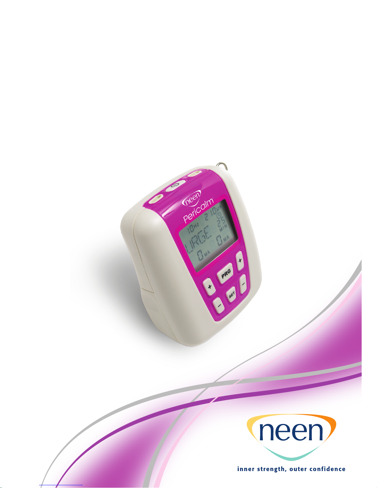
PERICALM™
Instruction Manual – GB
Mode d’emploi – FR
Manual de Instrucciones – ES
说明书 – SC

PERICALM™ Instruction Manual - GB
2
This instruction manual is valid for the Neen PERICALM™ unit. It is
published by Patterson Medical. Patterson Medical does not guarantee
its contents and reserves the right to improve and amend it at any time
without prior notice.
Amendments will however be published in a new edition
of this manual.
Revised Issue Date: 02/10/2010 Document Number: VM-NEEN400-OM001-3
Language Contents
4 - 23 Instructions for use - GB
24 - 43 Conseils d’utilisation - FR
44 - 65 Instrucciones de uso - ES
66 - 85 说明书 - SC

PERICALM™ Instruction Manual - GB
3
Contents
4Warnings
6Introduction
7Contraindications & Precautions
8Description of PERICALM™ Unit & Functions
9Quick Start Instructions
10 Setting up the Customised Programs MEM1-3
11 Continence Treatment Programs
12 Electrode Types & Tips
14 Care & Maintenance
15 Troubleshooting
16 Disposal
17 Specifications
18 - 20 Tables 201 - 206 Guidance and Manufacturer’s Declarations
21 Warranty
22 Clinical References

PERICALM™ Instruction Manual - GB
4
Warnings
•This unit must be used with the guidance of a Physiotherapist,
Doctor or Continence Advisor
•Type BF equipment, Continuous Operation
•Do not insert lead wires into a mains power supply
•Do not immerse the unit into water or any other substance
•Do not use the unit in the presence of a flammable anaesthetic gas
mixture and air or with oxygen or nitrous oxide
•If using rechargeable 9 Volt PP3 Nickel Metal Hydride batteries,
be sure to use a CE approved battery charger. Never connect the
PERICALM™ Continence directly to a battery charger or to any other
mains powered equipment.
•Never connect the PERICALM™ directly to a battery charger or any other
mains powered equipment
•Patient Electrodes are for single patient use only
•Use only CE approved vaginal or anal electrodes i.e. PERIFORM®+
or ANUFORM®
•Keep out of reach of children
•To avoid the effects of electromagnetic interference never use
the PERICALM™ device, within 4 meters of a cellular telephone or
near any other powerful radio interference producing equipment that
produces electrical sparks etc. In the electromyography (EMG) mode,
the PERICALM™ device may be susceptible to strong interfering radio
type emissions that may lead to temporarily increased EMG microvolt
readings. The reading will immediately return to the correct value when
the interference ceases. (Remember that a relaxed muscle should read
below 3.5 µvolts)
• Do not use this stimulator on your facial area unless you are under strict
guidance from a qualified Clinician.
•Application of electrodes near the thorax may increase the risk of
cardiac fibrillation.
•Operation in close proximity (e.g. 1m) to a shortwave or microwave
therapy equipment may produce instability in the stimulator output.
•Simultaneous connection of a patient to a high frequency surgical
equipment may result in burns at the site of the stimulator electrodes
and possible damage to the stimulator.
•No modification of this equipment is allowed!
Symbols on the rear cabinet of PERICALM™
Continence explained:
PERICALM™ Instruction Manual - GB
5
Follow
instructions
for use
Type BF
Equipment
Do not dispose in normal
dustbin (see page 16 for the
disposal instructions)
PERICALM™ Instruction Manual - GB
Introduction
Neuromuscular stimulation is the electrical stimulation of muscle and
nerve fibres that has been historically used as a form of pain relief and
pain prevention.
Therapists and Doctors have an increasing understanding of the mechanisms
which exist between muscles and nerves that in turn, makes it possible
to stimulate the neuromuscular system with precise electrical signals
to achieve a desired response.
The PERICALM™ is one of a new breed of modern neuromuscular
stimulators. It is a digital, dual channel unit and is used in the treatment
of patients suffering with symptoms of Stress Incontinence, Urge
Incontinence and a combination of the two. The PERICALM™ also
has a program for a pelvic floor workout, for pain relief and has three
customisable programs so the user can set their own parameters.
The PERICALM™ should be used in conjunction with a PERIFORM®+
(vaginal electrode), an ANUFORM® (anal electrode) or surface electrodes.
These need to be purchased separately.
Customer Care
We welcome constructive comments for the future
6

PERICALM™ Instruction Manual - GB
Contraindications & Precautions
Before using this equipment you must first seek the advice of your
Physiotherapist, Doctor or Continence Advisor.
Read this operating manual before using the PERICALM™
The PERICALM™ should not be used:
•By patients fitted with a demand style cardiac pacemaker unless
so advised by their Doctor
•During pregnancy [unless medically advised]
•By patients with undiagnosed pain conditions
•By patients with undiagnosed skin, vaginal or anal conditions
•With patients who have diminished mental capacity or physical
competence who cannot handle the device properly
•On anaesthetised or desensitised skin
•When driving a vehicle or operating potentially dangerous equipment
•If you have recently had any urinary tract infection or vaginal infection
treated prior to using the unit
•If you have any active disease in the area
•If there is any tissue damage in the area until it is healed
Do not place electrodes:
•Over carotid sinus nerves
•Over larynx or trachea
•Inside mouth
•Over the area of the heart unless so advised by your Doctor
•On your facial area unless under strict guidance from a qualified Clinician
•Take further advice before using if you have diabetes or uncontrolled
blood pressure
•If you have had any abnormal cervical smears - do not use the unit until
you are returned to ‘normal’ time between smears
•The patient should only use the unit as prescribed
If considering using the ANUFORM®(anal electrode) do not use if:
•You are suffering with acute haemorrhoids
•You have an anal fissure
•You have an acute attack of IBD (Crohns / Ulcerative Colitis) of the
lower bowel
7
PERICALM™ Instruction Manual - GB
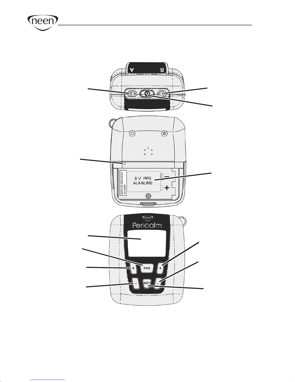
Description of PERICALM™ Unit & Functions
8
* PRG button Selects the desired programs - PR, STR1-2, URGE, FURG,
PFW, MEM1-3.
* SET button Hold down for three seconds. Changes the parameters
Pulse Rate, Pulse Width and Time for custom programs
MEM1-3.
Lock
button
Channel A Channel B
Power
Battery
compartment
LCD Display
Selects
Program
Channel A
Increase Intensity
Channel A
Decrease Intensity
Channel B
Increase Intensity
Channel B
Decrease Intensity
Changes
parameters
(prev was Set)
Top
Rear
Front
PERICALM™ Instruction Manual - GB
Quick Start Instructions
1. Insert a 9 volt PP3 Alkaline battery into the battery compartment.
(Can also use a rechargeable Nickel Hydride battery (which has
a longer life than the Ni-Cad rechargeable batteries)
2. Insert lead wire/s to channel A, and B if both channels are to be used.
Note: only one channel is required if using PERIFORM® + or ANUFORM®.
3. Attach lead wire/s to electrodes (vaginal, anal or surface electrodes).
4. Attach electrodes to correct body position. You should check with your
healthcare professional if you are in any doubt where to place electrodes.
5. Switch on the unit by pressing the Power button
6. Press the PRG (Program) button to select one of the programs
as detailed on page 11.
7. To start press channel A+ and B+ button if you are using both channels
until you reach the comfortable intensity.
8. To stop the program, press the Power button which will turn the unit off.
Lock Button
A ‘concealed’ Lock button is included on the PERICALM™ which locks the
customised or built in programs. It also allows the clinician to accurately
monitor ‘home compliance’ of the patient between appointments.
To Lock the Unit
1. Select the pre-set or customised program required. In the case of
a customised program, make sure that the pulse width, frequency, time
etc. are set-up correctly.
2. Remove the battery cover and using a thin rod, gently press on the lock
button as shown in the diagram on page 8 until you hear a double beep.
The unit is now ‘locked’ and cannot be altered until ‘unlocked’
To Unlock the Unit
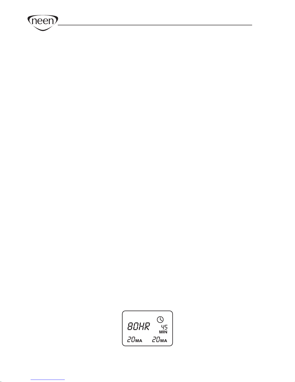
Remove the battery cover and press the lock button with a thin rod until a
single beep is heard. Now the LCD will display the average mA used on each
channel and the total hours the unit has been in use as shown in the diagram.
To return to normal ‘unlocked’ operation, simply press PRG.
9
Channel A
Hours Used
Channel B

PERICALM™ Instruction Manual - GB
Setting up the Customised Programs MEM1-3
1. Select MEM1 for a constant program by pressing the PRG button on
the front panel.
2. Hold down the SET button for three seconds to enter the setup menu.
The Hz symbol will flash.
3. Press the A+ or A- button select the desired Rate (Hz) from 2 to 100 Hz.
4. Press the SET button to select the Pulse width (µS). The µS symbol
will flash.
5. Press the A+ or A- button to select the desired Pulse Width from
50 to 450 µS.
6. Press the SET button to select the time. The MIN symbol will flash
and number of minutes will appear on the display.
7. Press the A+ or A- button to select the desired time from 5 to 60 minutes.
8. Press the SET button to select the work time in seconds WORK will
appear on the display. SEC symbol will flash.
9. Press the A+ or A- button to select the desired work time from
2 to 99 seconds.
10. Press the SET button to select the rest time in seconds REST will
appear on the display. SEC symbol will flash
11. Press the A+ or A- button to select the desired rest time from
2 - 99 seconds.
12. Press the SET button to select the ramp up time in seconds RAMP
will appear on the display. SEC symbol will flash
13. Press the A+ or A- button to select the desired ramp time from
0.2 - 9.9 seconds.
14. Pressing the SET button again will bring you back to the Rate setting.
15. Press the PRG button to save the program. Repeat the above
procedure to re-program.
Note: You must press the PRG button before locking the unit.
10

PERICALM™ Instruction Manual - GB
Continence Treatment Programs
The parameters in the table are suggested parameters only and should be used as that.
Please refer to the ACA Notes on Good Practice or The Chartered Society of
Physiotherapy Guidelines, to view the most up to date neuromuscular electrical
stimulation parameters.
As a clinician, you may prefer to use your own parameters to treat patients and it is
then ideal for you to use the customisable programs MEM1-3.
11
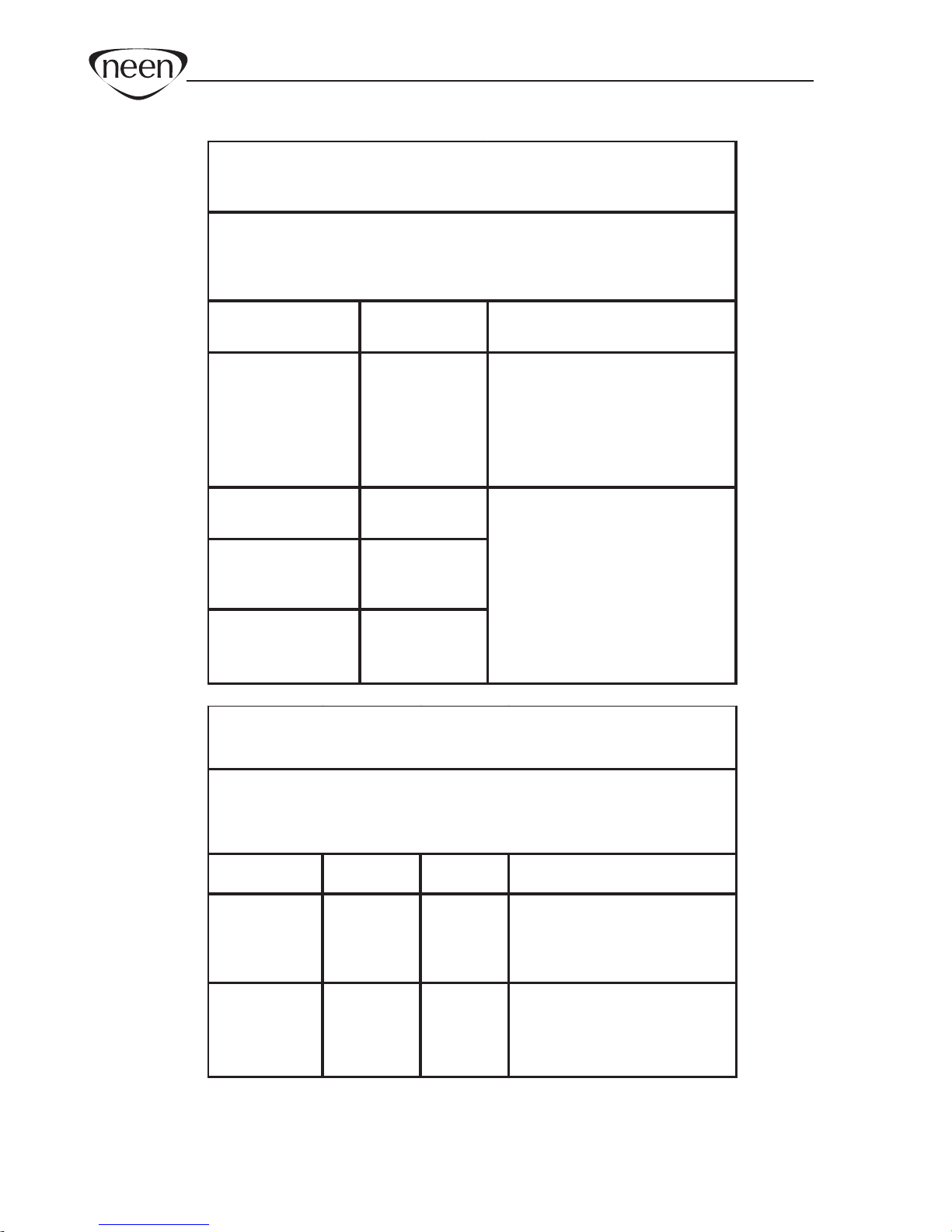
6 Sequential phases:
Phase 1: 2Hz for 4 min,
Phase 2: 10Hz for 10 min,
Phase 3: 15Hz for 5 min,
Phase 4: 20Hz for 5 min,
Phase 5: 30Hz for 5 min,
Phase 6: 10Hz for 5 min
All phases are 5 seconds work, 5 seconds rest at 220 µS,
0.8 seconds ramp.
Programs Hz PW
Ramp up Work Rest Overall
Rate μS
time in time in time in time in
seconds seconds seconds seconds
PAIN RELIEF 2 175 1 Cont Cont 25 min
PR
STRESS 1 30 200 1 5 5 25 min
STR1
STRESS 2 35 210 1 5 10 25 min
STR2
URGE 10 210 1 5 6 25 min
URGE
FREQUENCY/URGE
10 250 1 5 10 25 min
FURG
PELVIC FLOOR
WORK OUT AND
LACK OF
SENSITIVITY
(34 MIN)
PFW
CUSTOMISED
2 - 100 50 - 450
0.3 - 9.9 2 - 99 2 - 99 5 - 60
MEM 1
CUSTOMISED
2 - 100 50 - 450
0.3 - 9.9 2 - 99 2 - 99 5 - 60
MEM 2
CUSTOMISED
2 - 100 50 - 450 0.3 - 9.9
2 - 99 2 - 99 5 - 60
MEM 3

PERICALM™ Instruction Manual - GB
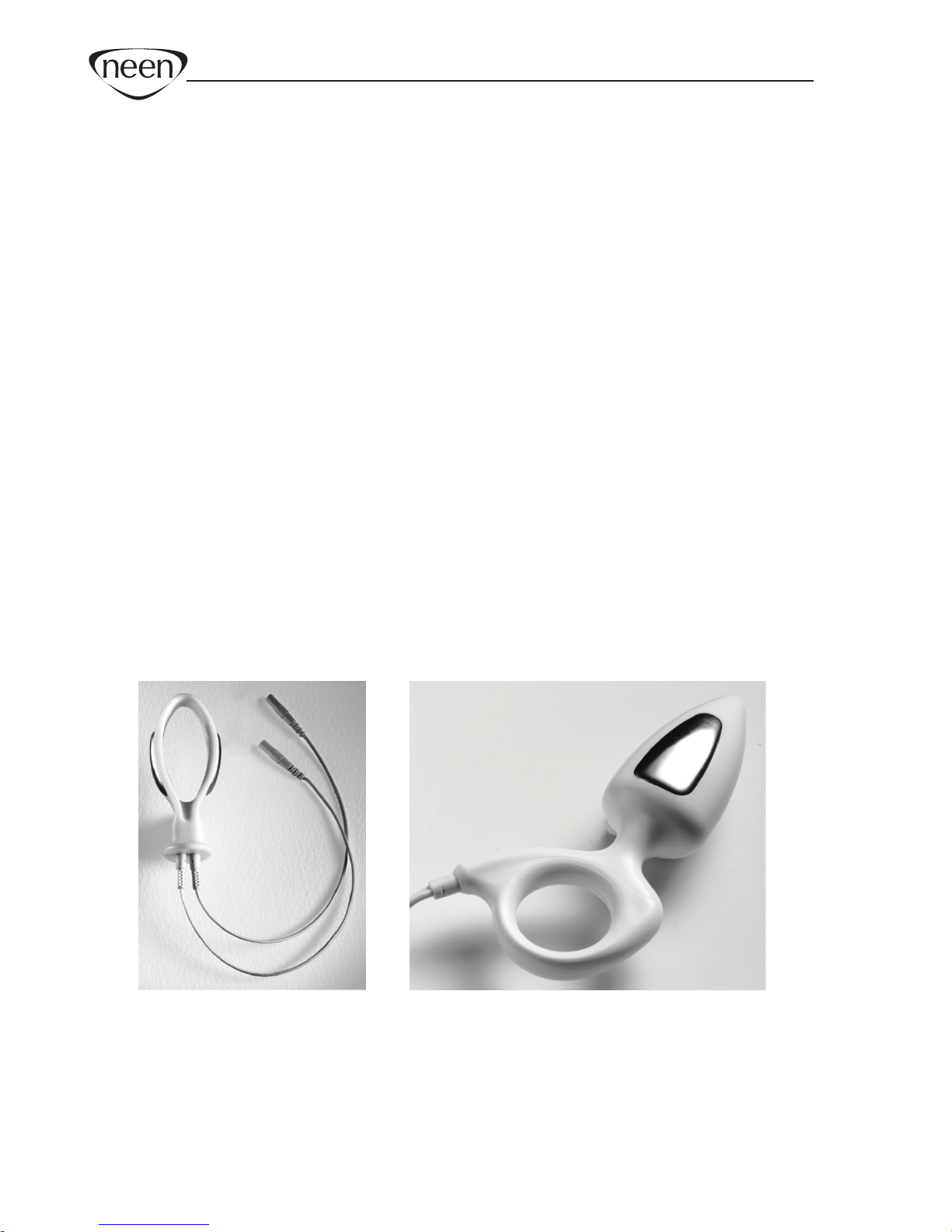
Electrode Types & Tips
Both internal and external electrodes can be used with this unit.
They are single patient use only.
Internal electrodes:
021972 PERIFORM
®
+ (vaginal electrode) 011503 ANUFORM
®
(anal electrode)
External self adhesive electrodes:
012571 50x50mm
012572 90x50mm
012574 30mm diameter
012575 50mm diameter
12

Tips
•If using an internal electrode, after use always wash it in warm soapy
water, rinse and dry thoroughly and carefully store it for your next
treatment session.
•Never let anyone else use your electrode.
•Follow all instructions provided with the electrode.
•If using self adhesive electrodes always cleanse the skin with soap
and water, then rinse and dry well in order to ensure good adhesion
of the electrodes.
•Clip away hairy skin using scissors, do not shave the area
•After using surface electrodes, place them back on the plastic film
they were packaged in and store them in a cool place i.e. the fridge.
•After repeated use, the sticky surface on the electrode will eventually
become dry. This surface is water based so by adding a few drops
of water will give you a few extra days of electrode life back!
•If you find the electrodes will not stick due to oily skin, cleanse the
skin with soap and water, then rinse and dry the area around the
electrode site. If this does not work, try cleansing the skin with a swab
impregnated with alcohol.
• The electrodes conductive material is water- based. If it becomes
saturated (e.g. from perspiration), it will lose its adhesive qualities. After
use leave the electrodes face up overnight to dry out (replace on plastic
film in the morning). At some point the electrodes will become dry.
Moisten the adhesive surface with a few drops of water, and apply onto
the plastic film overnight. This procedure will increase the electrode life
by few more days.
PERICALM™ Instruction Manual - GB
13

PERICALM™ Instruction Manual - GB
14
Care & Maintenance
Control Unit:
•Wipe the surface after use with a damp cloth or antiseptic wipe
•Do not use cleaning sprays or alcohol based cleaning solutions
Battery:
• To change the battery, open the battery door on the rear of the control
unit by pressing down on the raised rib pattern just below the belt clip.
Lift the battery out of the compartment. This is very easy and can be done
by the user.
•Check periodically for any discharge from the battery
•Remove battery completely from unit if not in use for any extended period
of time (typically one week)
•Low battery indicator of 6.9 volts shown on LCD display. When flashing
change battery for a new one
•Preferably use a PP3 alkaline battery
Lead Wires:
•
The lead wires should be handled carefully and never stretched, as this can
cause the stimulation to function below normal standards or not at all
•
Examine lead wires before each treatment for loose connections or damage
•Avoid twisting the lead wires
•Wipe lead wires after use with a damp cloth or antiseptic wipe
•Store the lead wires carefully after each use
Self-Adhesive Electrodes:
•
Check the short connectors have not become separated from the electrodes
•Replace electrodes onto plastic film after use. If they drop onto the floor
debris will adhere to conductive gel rendering the electrodes ineffective
Vaginal / Anal Probes
•Check the connectors have not become separated from the probe
•Before & after use always wash it in warm soapy water, rinse and dry and
carefully store
•
Never let anyone else use your electrode
•
Follow all instructions provided
with the electrode
Caution: Static electricity may damage this product
NOTE: Only Patterson Medical or appointed distributors/importers are
approved to undertake servicing.

Troubleshooting
The PERICALM™ is designed to detect any poor or intermittent connection
across the electrodes and to cut off the stimulation output (mA) when it does
so. This is for safety. It is designed to prevent the user from inadvertently
turning up the output stimulation current in the presence of a poor or
intermittent connection and then experiencing a large unexpected powerful
surge in the stimulation, if and when the connection is re-established.
If you experience a problem when using with internal probes, eg.
PERIFORM
®
+ or ANUFORM
®
, it may be due to a poor connection of the
two stainless steel electrode plates on shaft of the probe with your body.
If the probe is not fitting weel or momentarily becomes disconnected, for
example, when you shift position, you will see the “0” mA symbol flashing
on and off and the current will have been cut off.
If this occurs:
• Try to pull up the pelvic oor by lifting up the probe - this may re-establish
the connection.
• If the internal environment is dry, use a suitable, approved water based
lubricant such as KY (do not use standard creams or grease as the
lubricant must be electrically conductive).
• The position which leads to lack of conductivity: The best position to
conduct electrical stimulation using the vaginal probe is to stand up.
However, with the shape of Vaginal Probes on the market it is not ideal to
stand up as the probes tend to fall out. We recommend that the next best
position is to sit down and lean back slightly.
• If you think the probe itself is not working, wash it and hold it, using your
first finger and thumb to make a connection across the electrode plates.
Connect it to the stimulator as normal, increase mA and, if the probe
is functioning correctly, you will feel the stimulation mildly tickling your
hand. Try another probe to compare.
• Check if the dual conductor lead wire cable is not broken, as it might be
bent or pulled out too much which results in no conductivity: try another
cable. To check if the cable is good, cross the red and black pins together
so the metal is touching and increase mA. If the cable conducts the
electricity, the mA will go above 10mA and you may feel the stimulation
mild tickling in your fingers which holds the crossed pins.
PERICALM™ Instruction Manual - GB
15
PERICALM™ Instruction Manual - GB
Disposal
Applications
Information on disposal for users of Waste Electrical & Electronic
Equipment (WEEE) for private households:
Electrical and electronic products including batteries should not be
mixed with general household waste. For proper treatment, recovery
and recycling, please take these products to designated collection points,
where they will be accepted on a free basis.
•Promotes continence
•Increases muscle strength
•Maintains or improves range of movement
•Increases and improves the blood supply to the muscle
•Reduces pain
16

PERICALM™ Instruction Manual - GB
Specifications
17
1. Dual channel: individually isolated circuits.
2. Amplitude: 0 - 80 mA into 500 Ohm load; indication only. Actual mA
will tend to be less than indicated due to electrode impedance: at
1000 Ohms load (Electrodes in poor condition) the maximum will be
limited to 70 mA, at 1500 Ohms load the maximum will be limited to
65 mA.
3. Type: Constant Current, maximum output voltage 180 Volts
+10 / -30 Volts
4. Waveform: Asymmetrical, rectangular bi-phasic with zero
DC current.
5. Selectable pulse width: 50 µS – 450 µS (2% accuracy)
6. Pulse Rate selection: in the continuous mode 2 – 100 Hz
(2% accuracy)
7. Time duration of the treatment: 5 - 60 minutes.
(Custom programs only)
8.
Low Battery Indicator: If the battery goes below 6.9 volts +/- 0.2
volts the
battery symbol will flash on/off once every second.
9. Open Electrode Detect: If an open circuit is detected at the output
of channel A or B by: a probe not being attached, or with a probe
attached but not in position, when the unit intensity is ramped up to
5mA the output current will be reset at zero.
10. Ramp up time 0.3 - 9.9 seconds.
11. If the battery voltage is below 6.6 (+/- 0.2) volts the unit will not
turn on.
12. Physical dimensions: 80 x 67 x 45 mm.
13. Weight: 90 grams without battery, 125 grams with battery.
14. Environmental conditions for storage & transport: -10 to +50 degrees
Centigrade 0-90% Humidity.
PERICALM™ Instruction Manual - GB
18
Emissions test Compliance Electromagnetic environment –
guidance
Table 201: Guidance and manufacturer’s declaration
– electromagnetic emissions
product
The PERICALM™ product is intended for use in the electromagnetic
environment specified below. The customer or the user of the PERICALM™
should ensure that it is used in such an environment.
RF emissions
CISP R 11
Group 1 The PERICALM™product uses RF
energy only for its internal function.
Therefore, its RF emissions are very
low and are not likely to cause any
interference in nearby electronic
equipment.
RF emissions
CISP R 11
Class B
Harmonic emissions
IEC 61000-3-2
IEC 61000-3-2
Not applicable
Voltage fluctuations/
flicker emissions
IEC 61000-3-3
Not applicable
The PERICALM™product is suitable
for use in all establishments,
including domestic establishments
and those directly connected to the
public low-voltage power supply
network that supplies buildings used
for domestic purposes.
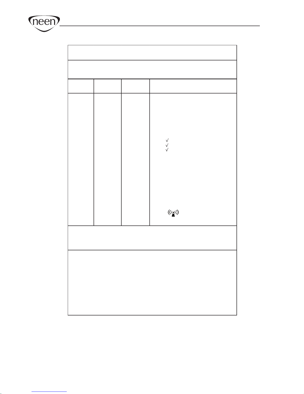
Immunity test IEC 60601
test level
Compliance
leve l
Electromagnetic environment–
guidance
Electrostatic
discharge (ESD)
IEC 61000-4-2
±6 kV contact
±8 kV air
±6 kV contact
±8 kV airFloors should be wo od, concrete or
ceramic tile. If floors are covered with
synthetic material, the relative
humidity should be at least 30 %.
Power frequency
(50/60 Hz)
magnetic field
IEC 61000-4-8
3 A/m 3 A/m Power frequency magnetic fields should
be at characteristic levels of a typical
location in a typical commercial or
hospital environment.
Table 202: Guidance and manufacturers declaration
– electromagnetic immunity
The PERICALM™product is intended for use in the electromagnetic environment specified
below. The customer or the user of the PERICALM™ product should ensure that it is used in
such an environment, and that precautions regarding that environment are heeded.
PERICALM™ Instruction Manual - GB
19
Immunity
test
IEC 60601
test level
Compliance
level
Electromagnetic environment –
guidance
NOTE 1: At 80 MHz and 800 MHz, the higher frequency range applie s.
NOTE 2: These guid elines may not apply in all situatio ns. Electromagnetic propagatio n
is affected by absorption and reflection from structures, objects and people .
Table 204: Guidance and manufacturer’s declaration –
electromagnetic immunity
The PERICALM™ productis intended for use in the electromagnetic environment specified below.
The customer or the user of the PERICALM™ product should ensure that it is used in such
an environment.
(a) Field strengths from fixed transmitters, such as base statio ns fo r radio
(cellula r/cordle ss) tele phones and land mobile radios, amateur radio, AM and FM
radio broadcast and TV broadcast cannot be predic ted theoretically with accuracy. To
assess the electromagnetic environment due to fixed RF transmitters, an
electromagnetic site survey should be consid ered. If the measured field strength in the
lo catio n in whic h PERICALM™
product is used exceeds the applicable RF
complia nce le vel above, the PERICALM™ product should be observed to verify
normal operatio n. If abnormal performance is observed, additional measures may be
necessary, such as reorie nting or relo cating the PERICALM™product.
(b) Over the frequency range 150 kHz to 80 MHz, field strengths should be le ss
than 3 V/m.
Conducted
RF
IEC 61000-
4-6
Radiated
RF
IEC 61000-
4-3
3 Vrms
150 kHz to
80 MHz
3 V/m
80 MHz to
2,5 GHz
3 Vrms
150 kHz
to 80 MHz
3 V/m
80 MHz to
2,5 GHz
Portable and mobile RF communic atio ns
equipment should be used no closer to any
part of the PERICALM™ product, including
cables, than the recommended separation
distance calc ulated from the equation
applic able to the frequency of the
transmitter.
Recommended separation distance
d = 1.2 P (150 kHz to 80 MHz),
d = 1.2 P (80 MHz to 800 MHz),
d = 2.3 P (800 MHz to 2.5GHz),
where P is the maximum output power
rating of the transmitter in watts (W )
according to the transmitter manufa cturer
and d is the recommended separation
distance in meters (m).
Field strengths from fixed RF transmitters,
as determined by an electromagnetic site
survey,
(a) should be le ss than the compliance le vel
in each frequency range;
(b) interference may occur in the vicinity of
equipment marked with the following
symbol:
PERICALM™ Instruction Manual - GB
20
150 kHz to
80 MHz
80 MHz to
800 MHz
800 MHz to 2,5
GHz
d =1.2 Pd=1.2 Pd= 2.3 P
0,01 0.12 0.12 0.23
0,10.380.3
80
.73
11.2 1.
22
.3
10 3.83.8 7.3
100 12 12 23
and mobile RF communications equipment and PERICALM™
Table 206: Recommended separation distances between portable
product
The PERICALM™ product is intended for use in an electromagnetic environment
in which radiated RF dist urbances are controlled. The customer or the user of the
PERICALM™ product can help prevent electromagnetic interference by
maintaining a minimum distance between portable and mobile RF
communications equipment (transmitters) and the PERICALM™ product as
recommended below, according to the maximum output power of the
communications equipment.
Separation distance according to frequency of
transmitter
For transmitters rated at a maximum output power not list ed above, the
recommended separation distance d in meters [m] can be estimated using the
equation applicable to the frequency of the transm itter, where P is the maximum
output power rating of the transmitter in watts (W) according to the transmitter
manufacturer.
NOTE 1: At 80 MHz and 800 MHz, the separation distance for the higher
frequency range applies.
NOTE 2: These guidelines may not apply in all situations. Electromagnetic
propagation is affected by absorption and reflection from structures, objects and
people.
Rated maximum output
power of transmitter
W
Other manuals for PERICALM
1
Table of contents
Languages:
Other Neen Medical Equipment manuals

Popular Medical Equipment manuals by other brands

Getinge
Getinge ArjoHuntleigh Flowtron ACS900 Instructions for use

Stryker
Stryker Prime 1115 Operation manual

Control Bionics
Control Bionics Neuronode Trilogy Attachment instructions

Datex-Ohmeda
Datex-Ohmeda S/5 M-NE12STPR Technical Reference Manual Slot

ITC
ITC HEMOCHRON Signature Elite Operator's manual

Iridex
Iridex Cyclo G6 quick guide


