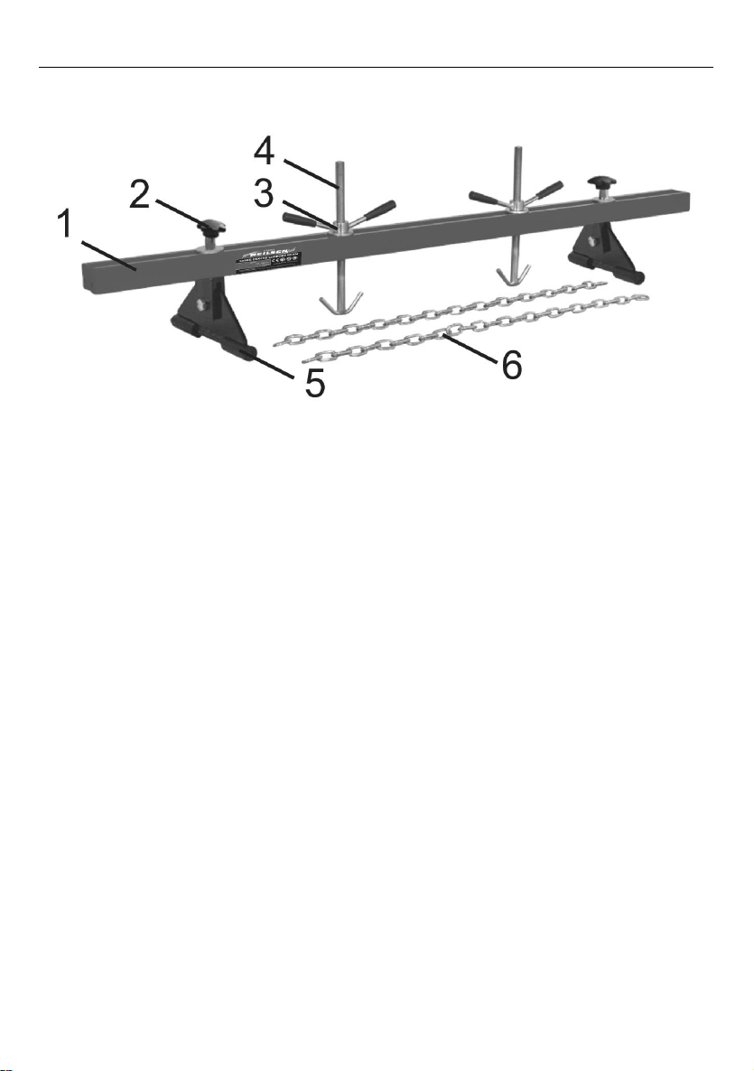
Neilsen CT4282 User manual

500KG ENGINE SUPPORT BEAM CT4282
INSTRUCTION MANUAL
IMPORTANT:
These instructions accompanying the product are the original instructions. This
document is part of the product, keep it for the life of the product passing it on to
any subsequent holder of the product. Read all these instructions before
assembling, operating or maintaining this product.
Cannon Tools Limited
Address: 20 Station Road, Rowley Regis, West Midlands, B65 0JU.U.K.

1
EC DECLARATION OF CONFORMITY
We CANNON TOOLS LTD
20 Station road, Rowley Regis, West Midlands,B65 0JU.U.K.
Declare that the following machine complies with the appropriate basic safety
and health requirements of the EC Directive based on its design and type, as
brought into circulation by us.
In case of alteration of the machine, not agreed upon by us, this declaration will
lose its validity.
Product description: 500KG ENGINE SUPPORT BEAM
Model: CT4282
Applicable EC Directives:
EC Machinery Directive 2006/42/EC
Harmonized standards
EN ISO 12100:2010, EN 13155:2003+A2:2009
20 Station Road, Rowley Regis, West Midlands, B65 0JU.U.K.
Mr. Gurcharan Tony Singh Sanghera
Managing Director
CANNON TOOLS LTD
2021-01-21

2
1. SPECIFICATION
Model: CT4282
Capacity: 500KG
Working range: 730 - 1480mm
Adjustable height: 0 - 205mm
2. IMPORTANT SAFETY INFORMATION
1. Ensure that the engine support is in good working order. Take action for
immediate repair or replacement of damaged parts. Use genuine parts only.
The use of unauthorised parts may be dangerous and will invalidate the
warranty.
2. Locate the vehicle in a suitable, well lit work area.
3. Keep work area clean and tidy and free from unrelated materials.
4. Ensure the vehicle handbrake is engaged and the engine/motor is switched
off.
5. Ensure all non-essential persons keep a safe distance whilst the engine
support is in use.
6. DO NOT use the engine support if damaged.
7. DO NOT allow untrained persons to operate the engine support.
8. DO NOT use the engine support for purposes other than that for which it is
designed.
9. Never try to move a running or hot engine. Allow sufficient time for the engine
to cool down entirely before beginning any operations.
10. Do not overload. Overloading could cause damage and/or failure of the
engine support and vehicle.
11. Ensure the rubber supports are securely located in the gutter of the vehicle’s
front wing panels. NOT ON TOP OF THE WINGS.
12. Once the support is positioned correctly, tighten all locking knobs, nuts and
bolts etc.,before applying a load.
13. Always check that the engine/gearbox is properly secured to the support via
a suitable chain or sling.
14. When not in use, store engine support in a safe, dry, childproof area.

3
3. TECHNICAL DESCRIPTION
1 . Beam 2.Lock nut 3. Grip handle
4. Adjustable Screw 5. Standing Bracket 6. Chain
4. UNPACKING AND CHECKING
Carefully remove the product from the packaging and examine it for any sign of
damage that may have happened during shipping. Lay the contents out and
check them against the parts shown below. If any part is damaged or missing;
please contact the seller and do not attempt to use the product.

4
5. ASSEMBLY
1. Insert a foot into the slot in the standing block . Align the holes in the two
components and join them together using an M12 x 25 bolt . Note that the
standing block has a threaded hole on one side and a clearance hole on the
other.
2. Place a large washer over the upstanding rod on the standing block and insert
the rod through the slot in the main support guide from underneath. Place a large
washer over the thread on top of the rod and secure the assembly to the main
support guide by screwing on a Look Nut. Assemble the other foot/standing block
and fix the assembly to the other end of the main guide beam in the same way.
3. Drop a large washer over an adjustable screw and screw a grip handle onto
the top of the adjustable screw. Screw the grip handle approximately half way
down the threads. Make up the second adjustable screw in the same way and
have both assemblies ready to drop through the slot in the main guide beam after
the beam has been placed over the engine bay.
4. The chains should also be attached when the guide beam is mounted over
the engine.

5
6. OPERATION
1. The fully assembled support beam is very heavy and should be lifted into
place by two people.
2. Loosen the Lock nut to allow the assemblies to slide and then locate the
rubber feet into the gutters of the vehicle’s front wing panels or close to the
suspension strut towers.
Note: Refer to the manufacturer’s handbook to identify engine lifting brackets.
3. Drop the adjustable screw assemblies through the slot in the main beam in
positions adjacent to the engine lifting points.
4. Attach the ends of the chain to the lifting brackets on the engine.
5. The chains may be attached to the lifting hooks in a single or looped chain
configuration.
6. Lower the adjustable screws and hook the chains around the hooks. In all
cases ensure that at least one link of the chain is hooked over the lifting hooks.
7. Tighten both Lock nut.
8. Progressively rotate the grip handles clockwise to tighten the chains and
support the engine.
9. On completion of the maintenance task, rotate the lifting handles
anticlockwise to release the tension on the chains.
10. Unhook the chains, loosen both Lock nuts and remove the engine support
from the vehicle.
11. Remove the chains from the engine lifting points.

6
7. MINTENANCE
1. BEFORE EACH USE, inspect the general condition of the tool.
Check for loose screws, misalignment or binding of moving parts,
cracked or broken parts and any other condition that may affect its
safe operation.
2. AFTER USE, clean external surfaces of the tool with clean, moist
cloth.
8. DISPOSAL
At the end of the machine's working life, or when it can no longer be repaired,
ensure that it is disposed of according to national regulations.
Contact your local authority for details of collection schemes in your area.
In all circumstances:
Do not dispose of this tool with domestic waste.
Do not incinerate.
9. EXPLANATION OF SYMBOLS
In this manual and/or on the machine the following symbols are used:
Denotes risk of personal injury, loss of life or damage to the tool in
case of non-observance of the instructions in this manual.
First read the instruction manual.
Wear safety goggles.
Wear gloves.
In accordance with essential safety standards of applicable
European directives

7
10. EXPLODED VIEW
CANNON TOOLS LTD
Add: 20 station road, Rowley Regis, west midlands,B65 0JU.U.K.
Made in China
Ref#
DESCRIPTION
QTY
Ref#
DESCRIPTION
QTY
1
Handle Sleeve
4
7
Bolt M12x25
2
2
Grip Handle
2
8
Standing Bracket
2
3
Washer
4
9
Rubber Block
4
4
Washer
2
10
Adjustable Screw
2
5
Beam
1
11
Chain
2
6
Standing Block
2
12
Look Nut
2
Table of contents
Other Neilsen Construction Equipment manuals
Popular Construction Equipment manuals by other brands

MULTIQUIP
MULTIQUIP LD6 installation instructions

Sky Climber
Sky Climber Sky Rig Assembly instructions

wavin
wavin Osma OsmaDrain Series quick guide

Epiroc
Epiroc DEQ171257 operating instructions

Fayat Group
Fayat Group DYNAPAC CA4600 instruction manual

Turbosol
Turbosol GIOTTO MONO Use and maintenance manual