Neilsen CT3583 User manual

IMPORTANT: PLEASE READ THESE INSTRUCTIONS CAREFULLY. NOTE THE SAFE OPERATIONAL REQUIREMENTS, WARNINGS AND CAUTIONS.
USE THE PRODUCT CORRECTLY AND WITH CARE FOR THE PURPOSE FOR WHICH IT IS INTENDED. FAILURE TO DO SO MAY CAUSE DAMAGE
AND/OR PERSONAL INJURY AND WILL INVALIDATE THE WARRANTY. PLEASE KEEP INSTRUCTIONS SAFE FOR FUTURE USE.
1. SAFETY INSTRUCTIONS
2. INTRODUCTION & CONTENTS
WARNING! Ensure Health and Safety, local authority and general
workshop practice regulations are adhered to when using tools.
WARNING! Always use caution when working around fuel
systems. The fuel in the fuel rail may be pressurised even if
the engine is not running.
IMPORTANT: These instructions are provided as a guide only.
Always refer to the vehicle manufacturer’s service instructions,
or a proprietary manual, to establish the current procedure and
data, also any warnings or cautions particular to the vehicle.
DO NOT use the set if any parts are missing or damaged.
DO NOT use this tool for any purpose other than that for which it is
designed.
Switch off vehicle's ignition and disconnect the battery before
commencing work under the bonnet.
You must follow the vehicle's service manual cautions when
working around the air bag system. If the cautions are not
followed the air bag may deploy unexpectedly even after the
ignition is turned ‘OFF’, resulting in personal injury.
Never lay tools on the vehicle's battery. This may short the
terminals together, causing harm to yourself, the tools, or the
battery.
Operate in a well ventilated area. Do not inhale fuel vapours.
Wear approved eye protection. A full range of personal safety
equipment is available from your dealer.
Wear suitable clothing to avoid snagging. Do not wear jewellery
and tie back long hair.
Keep children and other unauthorised persons away from the
working area.
Keep yourself, tools, and test equipment away from hot engine parts.
Always keep a fire extinguisher close by, that is suitable for fuel/
electrical/chemical fires.
NEVER smoke or have open flames near vehicle.
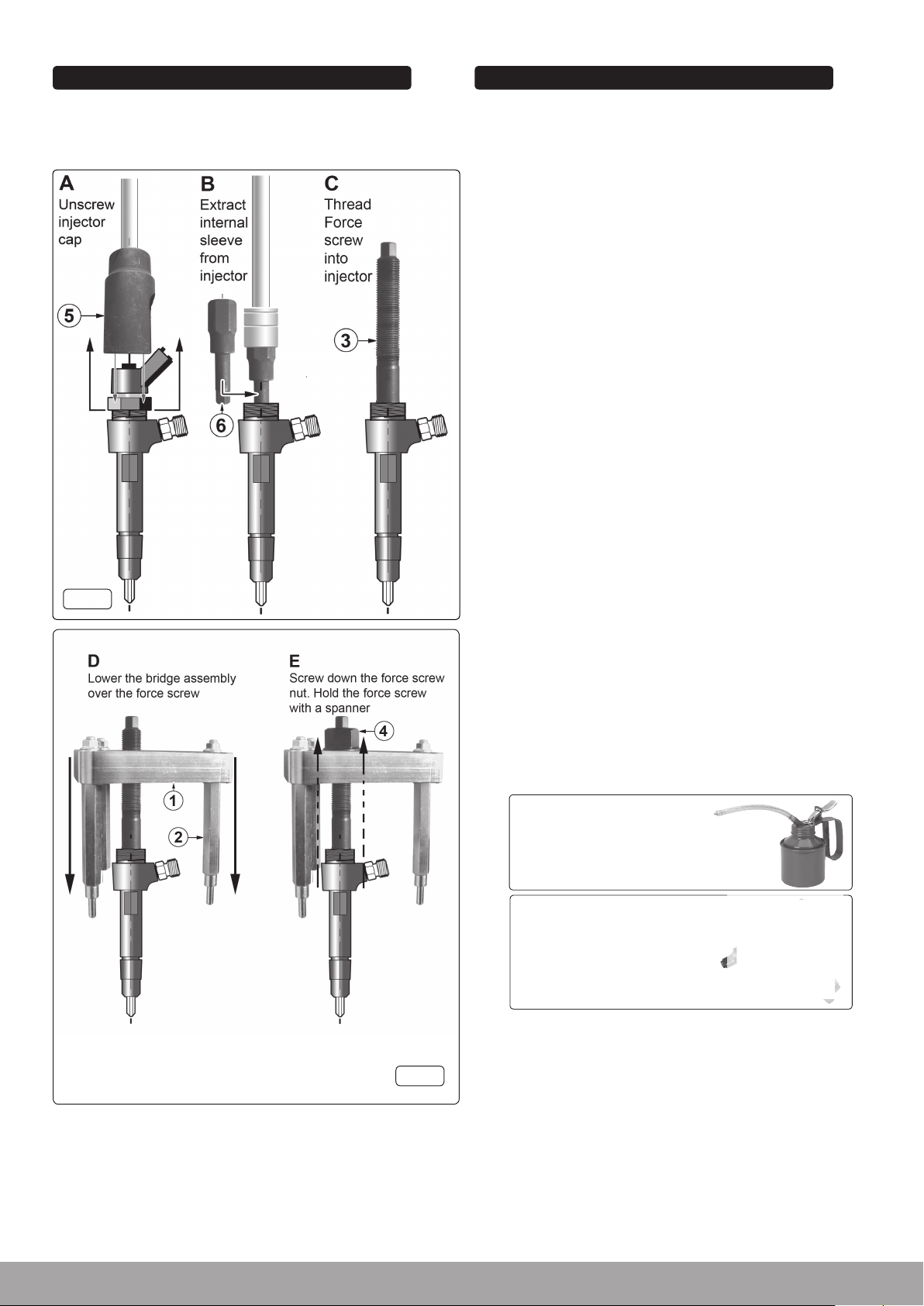
Always relieve fuel pressure before disconnecting fuel lines from
injectors.
Use a rag to cover fuel line fittings, when connecting or
disconnecting fuel lines. Avoid contact with fuel.
Clean up all fuel spills immediately and dispose of all rags properly.
Maintain the tool components in good and clean condition for best
and safest performance.
When work on the vehicle is finished, ensure all connections on
vehicle are restored, and that there are no tools left in the engine
bay.
Replace tools in the carrying case and store in a safe, dry,
childproof location.
Comprehensive set for removing Citroen/Peugeot 2.0/2.2HDi 16v fuel
injectors. Allows the removal of seized injectors without the need to
remove the cylinder head. Bridge fits perfectly on the cylinder head
preventing damage to the area surrounding the injector. Supplied in
carry-case.
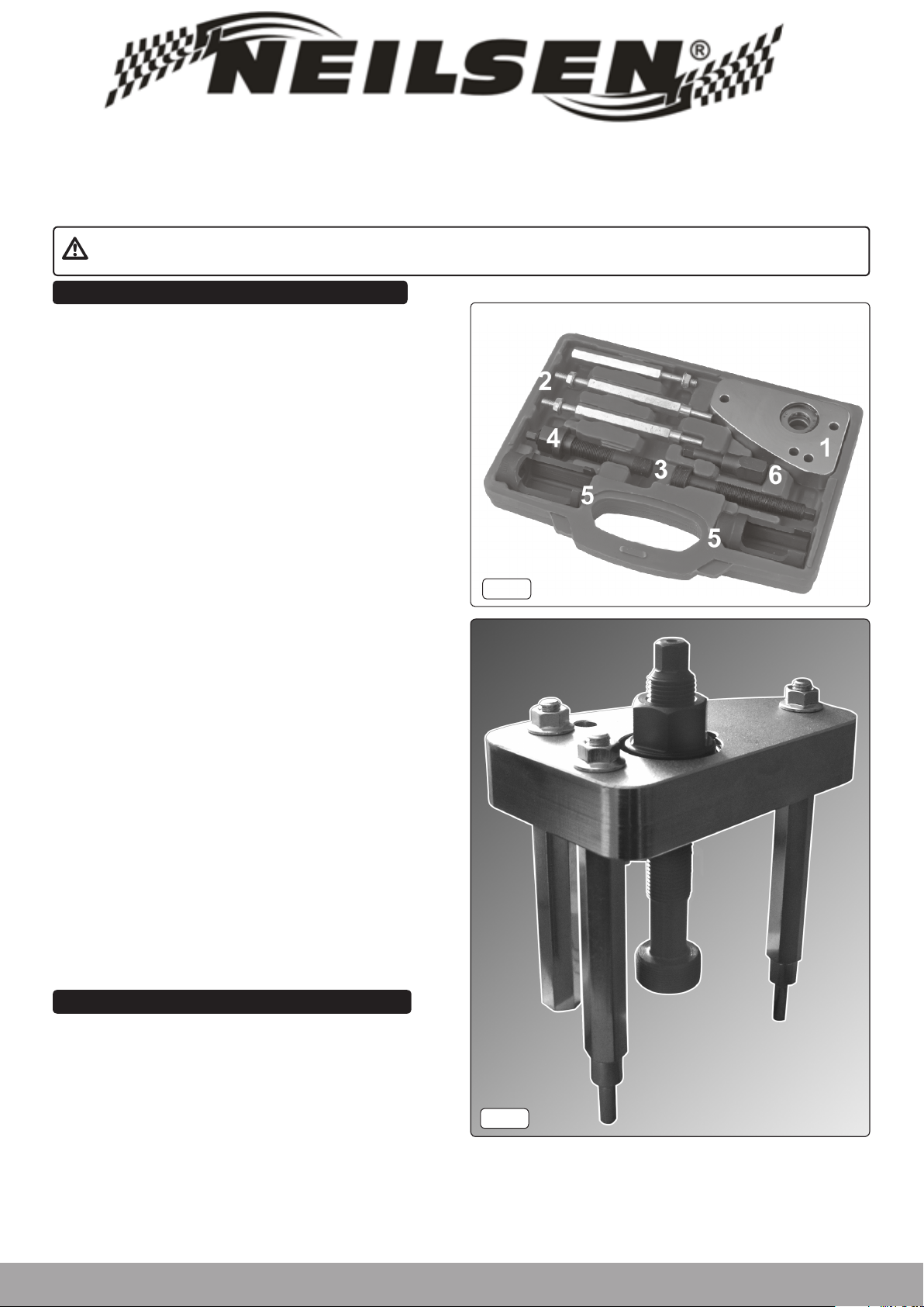
Contents: (refer to fig.1)
Item Description
1 Bridge
2 3 x Bridge Legs
3 2 x Force Screws - Thread 17mm, 25mm x Pitch 1mm
4 Force Screw Nut
5 Injector Sockets 25mm, 29mm
6 Security Hex Key - 10mm
fig.2
DIESEL INJECtOR PULLER
CT3583
For Citroen and Peugeot
fig.1
CANNON TOOLS LTD
Add: 20 station road, Rowley Regis, west midlands,B65 0JU.U.K.

3. ASSEMBLY
3.1. Referring to the individual components in fig.1. assemble the
Injector Puller minus the force screw as shown in fig.2. overleaf. a
different configuration of the bridge legs may be needed
depending on engine.
fig.4
4. OPERATION
4.1. Before working on the fuel system, make sure that the fuel system
is NOT pressurised. Refer to the manufacturer's instruction
manual on how to de-pressurise the system.
4.1.1. Disconnect the injector wires and connections as per the
manufacturer's instructions.
4.1.2. Remove any carbon build up from around the injector.
4.1.3. Remove the cap from the injector using the appropriate size
socket (fig.3A).
4.2. Removing Inner Sleeve. (fig.3).
4.2.1. Remove the internal parts from the injector to gain access to use
the security hex key (fig.3.6). It may be necessary to remove the
injector veins by force. Insert the security hex into the inner sleeve.
Turn the security hex anti-clockwise using a 21mm socket to
remove the inner sleeve (fig.3B).
4.2.2. Select the appropriate force screw and screw into the threads of
the injector and tighten with a suitable spanner (fig.3C).
4.3. Removing the injector. (fig.4).
It will be necessary to remove the engine cam cover and possibly
a manifold bolt, please refer to the manufacturer's manual for
instruction. The removal of certain bolts from the engine will allow
suitable space and support for the bridge legs to use.
4.3.1. Slide the bridge assembly over the force screw, inserting the legs
into the appropriate holes for a sturdy footing (fig.4D).
Note: One leg is flat and is to be used on the top of the cylinder head
and not to be inserted into a bolt hole.
4.3.2. Screw the force screw nut onto the force screw until finger tight.
4.3.3. Using appropriately sized spanners, hold the force screw
securely with one spanner, and tighten the nut with the other, the
injector should gradually slide out.
Note: An approximate force of NO MORE THAN 150Nm should be
applied to the nut, and a socket should NOT be used.
Whilst applying force, constantly check the seating of the tool and
ensure that there is no twisting of the bridge assembly.
4.3.4. If the injector cannot be removed, it may be necessary to use a
suitable penetrating oil and leave for a period of time, before
applying force again. If the injector still cannot be removed, consult
a main dealer or a diesel specialist, to avoid damage to the engine.
4.3.5. When an injector has been removed, it is recommended that only a
new or refurbished injector is fitted. Follow the manufacturer's fitting
and safety instructions.
fig.3
ALWAYS KEEP FORCE SCREW
WELL LUBRICATED.
DO NOT USE AIR TOOLS,
IMPACT WRENCHES,
BREAKER BARS
OR SOCKETS
www.cannontools.co.uk
Table of contents
Popular Medical Equipment manuals by other brands

Invacare
Invacare ICCG 1143214 Installation and operating instructions

Winncare
Winncare POSTURA user manual

VOP
VOP SlitPrecise SP100 user manual

Avive
Avive AED quick start guide

Mindray
Mindray Passport 8 Quick reference guide

Integra LifeSciences
Integra LifeSciences MAYFIELD Infinity Support System instruction manual

Stryker
Stryker Visum 300 Assembly, operation and maintenance instructions

Pivotell
Pivotell Mark 3/11 instructions

Teleflex
Teleflex LMA Unique Cuff Pilot Instructions for use

Ambu
Ambu Mark IV Adult Instructions for use

ResMed
ResMed AirFit P10 user guide

IngMar Medical
IngMar Medical ASL 5000 Lung Solution user manual