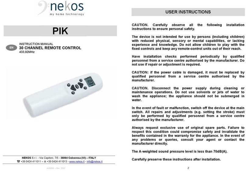
nekos PIK User manual

Code 4420066 Edition 1 of 10/12/2011
PIK
30
CHANNEL REMOTE CONTROL
433,92
MH
Z
MANUAL FOR INSTALLATION AND USE

Page 2
The device described in this manual has been manufactured in accordance with safety
standards and conforms to the stipulations of current standards in force. When correctly
assembled, installed and used according to the present instructions, it will not generate any
danger for persons, animals or items.
Products subject to EU directives comply with the essential requirements stipulated by
the latter. markings mean that our products can be sold and installed throughout the
European Union without any further formality.
The marking on the product, packaging and indications for use provided with the
product indicate ‘presumed conformity to the directives’ issued by the European Community.
The manufacturer holds the technical archive with documentation providing that
products have been examined and evaluated for conformity to directives.
Symbols used in the manual
DANGER
This indication draws the attention about potential dangers for safety and
health of peoples and animals.
INFORMATION
This information gives further suggestions.
ATTENTION
This indication draws the attention about potential dangers for the product
itself.
WARNING
This indication draws the attention about potential damages to goods.
ENVIRONMENTAL
INSTRUCTION
Environmental indication draws the attention about potential dangers for
the environment.
Contents
1. Safety indications..........................................................................................................................3
♦General notes.........................................................................................................................3
♦Notes for functioning and use.................................................................................................3
2. Technical data...............................................................................................................................4
3. Technical and constructional information ......................................................................................4
4. ID plate and marking data.............................................................................................................5
5. Instructions for start-up .................................................................................................................5
♦Standby state.........................................................................................................................5
♦Wait state...............................................................................................................................5
♦Selection of the channel.........................................................................................................5
♦Storage of the M1 and M2 memory groups ............................................................................5
♦Control of a stored sequence - M1 and M2 Memories............................................................6
♦F1 and F2 Function buttons....................................................................................................6
oSash / hopper - ventilation application...............................................................................6
oApplication for SYSTEM TRIS motors – 3 Motors for: window, blinds and rolling shutter...7
6. Battery status indication................................................................................................................7
7. Environmental protection...............................................................................................................8
8. Recall to main principles of warranty certificate.............................................................................8
9. Certificate of conformity ................................................................................................................8

Page 3
1. Safety indications
General notes
ATTENTION: Before installing this appliance, ensure all safety indications have been
read carefully and understood in order to prevent contact with electricity, injury or any
other incident. The manual should be conserved for further consultation at a later date.
WARNING DANGER OF EXPLOSION IF THE BATTERIES ARE REPLACED WITH A DIFFERENT TYPE OF
BATTERY.DISPOSE OF THE USED BATTERIES IN COMPLIANCE WITH CURRENT REGULATIONS
The manufacturer accepts no responsibility for damage to people, animals or things
incurred by improper use.
Use for any applications other than those indicated must be authorised by the
manufacturer after technical review of the assembly.
Plastic bags, polystyrene, small metal parts such as nails, staples etc. should be placed out
of the reach of children as they constitute a potential source of risk.
Do not use solvents or jets of water to wash the appliance. The appliance should not be
submerged in water.
Notes for functioning and use
PIK is a radio transmitter – or simpler a remote control – to command devices provided of a receiver
with the same code protocol or the same transmission philosophy. For further details see chapter
“Technical data”.
This product is designed to be used with the manufacturer's original products. Use with any
other products may result in damage or malfunctions.
The initial start-up of the radio remote control should be carried out by a skilled and qualified
person following the manufacturer's instructions.
After removing packaging, check for any damage on the appliance.
Before using the remote control, check that installed batteries have the same nature, quality
and tension as those indicated on the technical data label on the appliance.
This machine is destined exclusively for the use for which it has been designed and the
manufacturer accepts no responsibility for damage incurred by improper use.
Repairs should only be performed by qualified personnel at assistance centres authorised
by the manufacturer.
The product must be disposed of in compliance with local environmental regulations and not
as household waste.
Run-down batteries do not belong in normal household waste. They must be disposed of
properly.
For any doubts, contact your local waste collection company.
The batteries must always be replaced with suitable models corresponding to the
specifications provided on the label attached inside the battery compartment door. Failure to
observe this rule may compromise safety and void the warranty.

Page 4
2. Technical data
Type Multi-channel radio remote control with
microprocessor
Number of transmission
channels 30
Transmission frequency 433.92 MHz
Modulation ASK
Power supply voltage 2 1.5V batteries - type AAA
Operating voltage 1.8V - 3.3V
Estimated lifetime of the
batteries > 2 years (assuming an average use of 1 minute per
day)
Display LCD (liquid crystal display)
Visualization
♦
2 digits (selected channel);
♦
Battery charge status indicator;
♦
Transmission status;
♦
Specific function letters
Display dimensions 18.5x13.5 mm
Encoding HCS301
Independent codes >18 x 10^18 “rolling code” combinations
Absorption in standby < 1 µA
Absorption in transmission < 20 mA
Keypad
♦
Operational control (UP ARROW,DOWN ARROW,
STOP);
♦
2 Function buttons (F1,F2);
♦
1 Memory button (M);
♦
1 Channel button (CH);
Transmission distance 50 m – (with charged batteries)
Regulatory references Approved according to the R&TTE Directive
1999/5/EC – Directive 1999/5/EC of the European
Parliament and Council of 9 March 1999.
Dimensions 145x38.5x22.5
Weight 76 g
3. Technical and constructional information
The PIK radio remote control transmits radio waves at the frequency of 433.92 MHz. It has a
protocol that changes its code at each transmission (rolling code) according to a predetermined
algorithm with a total of over 18 x 10^18 possible combinations.
30 Direct transmission channels (from 01 to 30). With the F1 and F2 functions implemented,
there can be as many as 90 control outputs for specific transmission processes.
The command issued can be received by an electrical appliance equipped with a receiver of the
same nature which has already been set up for reception.
The casing is constructed in recyclable thermoplastic material (PC-ABS -(Polycarbonate-
Acrylonitrile Butadiene Styrene)) which is particularly shock resistant.
The batteries are enclosed by a snap door with the product's technical data label attached to it.
Powered by 2 AAA 1.5V batteries. (The radio remote control works with voltages from 1.8V to
3.3V).
Provided with a liquid crystal display and silicone control keypad.
The “free-field” transmission distance covers a sphere with a radius of 50 m.
Approved according to Directive 1999/5/EC of the European Parliament and European Union
Council.

Page 5
4. ID plate and marking data
PIK remote controls have marking and are destined for use in the European Union without further
requirements. The marking on the product, packaging and indications for use provided with the product
indicate ‘presumed conformity to the directives’ issued by the European Community.
The manufacturer holds the technical archive with documentation
providing that products have been examined and evaluated for
conformity to directives.
ID plate data are indicated on a polyethylene adhesive label applied on
the product, printed in black on a grey background; see example aside.
5. Instructions for start-up
THESE INSTRUCTIONS ARE INTENDED FOR TECHNICAL AND SPECIALIZED PERSONNEL.
THUS BASIC SAFETY AND WORKING TECHNIQUES ARE NOT DISCUSSED.
Standby state
When the batteries are inserted, the radio remote control goes into a standby state; the display is
off and the microprocessor is in the power down state, so the entire device is in a state of very low
consumption.
The radio remote control returns to this state whenever 30 seconds have passed since the last
button was pressed.
Wait state
If any of the 7 buttons is pressed when the radio remote control is in standby, it awakens and enters the
wait state. The display shows the channel (one of the 30) selected before the radio remote control went
into standby state.
Selection of the channel
To select a (new) channel, press the CH button; the displayed channel starts flashing. Use the
▲(UP) arrow or ▼(DOWN) arrow buttons to select the desired channel, which flashes. By pressing
the CH button again, the channel display becomes steady-on.
If the newly selected channel is not activated by pressing the CH button, after a standby or the next
time the radio remote control passes to the wait state, the last channel that was previously
activated will appear on the display.
Storage of the M1 and M2 memory groups
The “sequence storage” state (Mbutton) provides the possibility to assign two distinct “memory
groups”, i.e., two memories. The storage is carried out as follows.
Memory M1
♦
Press the Mbutton for 5 seconds to store the memory 1; the icon M1 appears flashing on
the display.
♦
Scroll through the channels using the ▲▼ arrows, and the various channels will flash. To
enter the channel in the memory, press the STOP button, the channel stops flashing and
becomes steady-on; carry out this operation for all the channels you would like to store, up
to a maximum of 10 channels.
♦
To exit the channel storing mode, press the Mbutton again for at least 1 second.
♦
To erase the memory, go to the channel 00 and press the STOP button. After the memory has
been erased, all the channels start flashing. To exit, press the Mbutton again for 1 second.

Page 6
Memory M2
♦
Press the M button for 5 seconds, and the flashing icon M1 appears. Now press the CH
button and the icon M2 will appear flashing on the display.
♦
Scroll through the channels using the ▲▼ arrows, and the various channels will flash. To
enter the channel in the memory, press the STOP button, the channel stops flashing and
becomes steady-on; carry out this operation for all the channels you would like to store, up
to a maximum of 10 channels.
♦
To exit the channel storing mode, press the M button again for at least 1 second.
♦
To erase the memory, go to the channel 00 and press the STOP button. After the memory
has been erased, all the channels start flashing. To exit, press the M button again for 1
second.
Checking the composition of a memory sequence
♦
From the wait state, press the M button; the M1 icon will be activated.
♦
The stored sequence of channels appears on the display (e.g.: 1-2-3-4-pause, 1-2-3-4-
pause, etc.).
Control of a stored sequence - M1 and M2 Memories.
Starting from the wait state, press the Mbutton and the steady-on M1 icon will appear on the
display; using the ▲▼ buttons activates the function, transmitting the command to the channels of
the M1 sequence. The stored channels scroll cyclically and continuously on the display.
Starting from the wait state, press the M+CH button and the steady-on M2 icon will appear on the
display; using the ▲▼ buttons activates the function, transmitting the command to the channels of
the M2 sequence. The stored channels scroll cyclically and continuously on the display.
The STOP button stops the command.
Press the Mbutton once to exit from the memory sequence control state, and the M1 or M2 icon
disappears; now it is possible to activate the commands of all the individual channels.
F1 and F2 Function buttons
The F1 and F2 function buttons are dedicated exclusively to the applications controlling the
dedicated motors constructed to carry out certain tasks in complete autonomy, that is:
A. Motors dedicated to ventilation on sash / hopper windows;
B. Motors for applications controlling the SYSTEM TRIS.
A. Sash / hopper - ventilation application
Before each operation with the F1 and F2 functions, the desired channel should be selected
and then the function can be executed:
♦
Sash function. Press the F1 button; the steady-on F1 icon appears on the display.
Pressing the ▲button activates the “Sash Function”. The window can be opened
manually.
To cancel the F1 function, first close the window and then press the F1 button; the icon
disappears from the display.
♦
Ventilation function. Press the F2 button; the steady-on F2 icon appears on the display.
Pressing the ▲button activates the automatic “Ventilation Function”.
To cancel the F2 function, press the F2 button; the F2 icon disappears from the display.
Once inside the menu of one of the two “memory groups” (M1 or M2), whenever
the F1 or F2 button is pressed, the respective steady-on icons appear on the
display (M1, M2, F1, F2). This means that the respective group of channels can
now be controlled.

Page 7
B. Application for SYSTEM TRIS motors – 3 Motors for: window, blinds and rolling
shutter
♦
The actuator for the window is controlled directly by the channel selected with the ▲▼
buttons.
♦
To operate the motor of the internal blinds, the F1 function is used.
Press the F1 button; the steady-on F1 icon appears on the display. Pressing the
▲(open) ▼(close) buttons activates the command to the internal blinds.
To cancel the F1 function, press the F1 button again; the icon disappears from the
display.
♦
To operate the motor of the external rolling shutter, the F2 function is used.
Press the F2 button; the steady-on F2 icon appears on the display. Pressing the
▲(open) ▼(close) buttons activates the command to the external rolling shutter.
To cancel the F2 function, press the F2 button again; the icon disappears from the
display.
Once inside the menu of one of the two “memory groups” (M1 or M2), whenever
the F1 or F2 button is pressed, the respective steady-on icons appear on the
display (M1, M2, F1, F2). This means that the respective group of channels can
now be controlled.
WARNING:
For all the other “normal” applications – i.e., those not supported by the devices
described above - where the radio remote control is used, regardless of the channel
number on which it is set, if the steady-on F1 or F2 icon appears on the display,
NOTHING MOVES when the ▲▼ buttons are pressed because these functions are not
associated with any type of command.
IN THIS CASE,THE F1 AND F2 ICONS SHOULD NEVER APPEAR ON THE DISPLAY DURING USE.
The simultaneous combination F1+F2, active on the display, is a special function regarding certain
machines which is described in the manual of the specific machine.
6. Battery status indication
The level of the battery charge is measured at each passage from the standby state to the wait
state. The level is shown on the display using the battery indicator:
Level above 2.6V: 3 bars lit
Level between 2.4V and 2.6V: 2 bars lit
Level between 2.2V and 2.4V: 1 bar lit
Level below 2.2V: 0 bars lit – all off
7. Environmental protection
All materials used in the manufacture of this appliance are recyclable.
We recommend that the device itself, and any accessories, packaging, etc. be sent to a centre
for ecological recycling as established from laws in force on recycling.
The device is mainly made from the following materials:
Iron Aluminium Cuprum Zinc Silicon Plastic of various type
Dispose materials in conformity with local regulations about removal.
To disassemble device, after removing battery cover, unscrew 2 screws fixing shells.

Page 8
8. Recall to main principles of warranty certificate
The manufacturer will guarantee good function of the appliance. The manufacturer shall undertake to
replace defective parts due to poor quality materials or manufacturing defects.
The guarantee covers products and individual parts for 2 years from the date of purchase. The latter is
valid as long as the purchaser possesses proof of purchase and completion of all agreed conditions of
payment.
Guarantee of good function of appliances agreed by the manufacturer implies that the latter undertakes
to repair or replace free of charge and in the shortest period possible any parts that break while under
warranty. The purchaser is not entitled to any reimbursement for eventual direct or indirect damage or
other expenses incurred. Attempt to repair by personnel unauthorised by the manufacture shall render
the warranty null and invalid.
The warranty does not cover fragile parts or parts subject to natural wear and tear or corrosion,
overload, however temporary etc. The manufacturer will accept no responsibility for eventual damage
incurred by erroneous assembly, manoeuvre or insertion, excessive stress or inexpert use.
Repairs performed under guarantee are always "ex-factory of the manufacturer". Respective transport
expenses (out/back) are the responsibility of the purchaser.
Certificate of conformity
NEKOS
S.r.l. - Via Capitoni, 7/5
36064 Mason Vicentino (VI) – ITALY
Telephone 0424 411011 – Fax 0424 411013
www.nekos.it inf[email protected]
NEKOS S.r.l. company declares that the below indicated remote transmitter is manufactured in
compliance with the following Directives:
R&TTE 1999/5/CE - (Directive 1999/5/CE of Parliament and European Council of 9
th
March
1999);
Directive 2004/108 CE - (EMC Directive) and following amendments;
Directive 2006/95 CE - (Low Tension Directive) and following amendments.
Series number: (See reference on label attached on the apparatus).
Year: 2012
Electrical device:
Mason Vicentino, 12/03/2012
President: Giuliano Galliazzo …………………………………
NEKOS S.r.l.
I - 36064 - MASON VICENTINO (VI) - Via Capitoni, 7/5
Telephone (+39) 0424 411011 Fax (+39) 0424 411013
Model Description
PIK RADIO TRANSMITTER30 CHANNELS - 433,92 MHz
Table of contents
Other nekos Remote Control manuals
Popular Remote Control manuals by other brands

Mi-Light
Mi-Light MiBOXER FUT086 instructions

Scientific Atlanta
Scientific Atlanta AT8420TM user guide

Clas Ohlson
Clas Ohlson 50027 operating instructions
Itowa
Itowa RUNNER G7 user manual
MyEnergy Domain
MyEnergy Domain MyE Smart Remote user guide
Universal Remote Control
Universal Remote Control PHAZR-5 operating instructions
