NELSEN WATER Signature Series User manual
Signature Series
User Guide
Softeners & Filters
1", 1-1/4", 1-1/2", 2" & Twin Control Valves
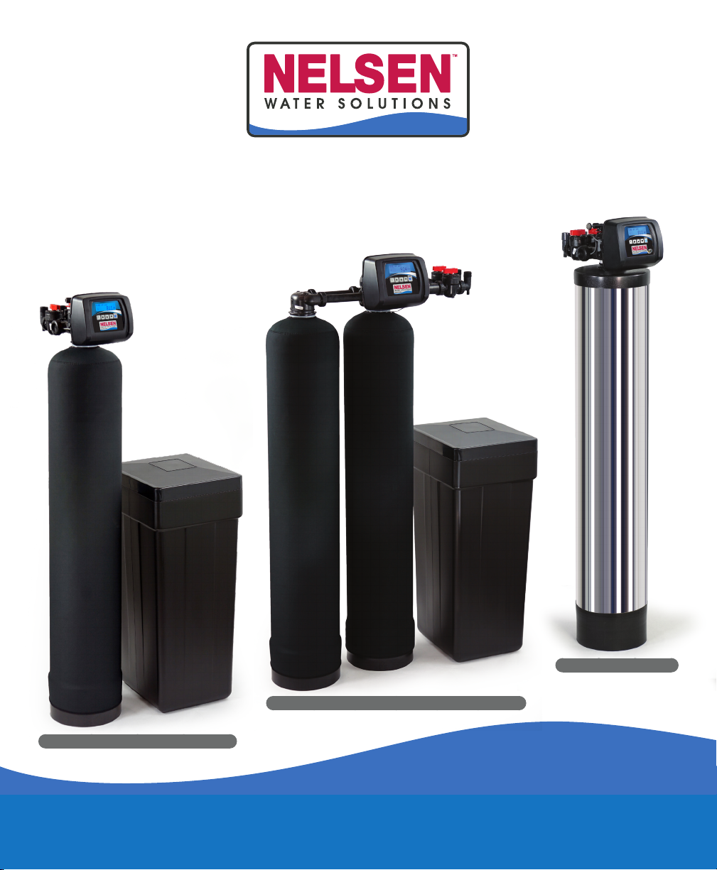
Signature Series
Single Tank
AIO
Twin Tank
AANelsen Water Solutions User Guide
Table of Contents
Display Screen Color Code........................................................................................................................................................................................... A
Regeneration & Error Screens.................................................................................................................................................................................... A
Bypass Operation .................................................................................................................................................................................................................... 1
Button Operation & Function....................................................................................................................................................................................... 1
Setting Time of Day............................................................................................................................................................................................................... 1
User Displays................................................................................................................................................................................................................................ 2
User Displays - Resetting Salt Level ................................................................................................................................................................... 2
Nelsen Water Solutions Systems........................................................................................................................................................................... 3
Water Softener Maintenance...................................................................................................................................................................................... 4 - 5
Error Codes..................................................................................................................................................................................................................................... 6
Troubleshooting......................................................................................................................................................................................................................... 7 - 8
Warranty............................................................................................................................................................................................................................................. 9
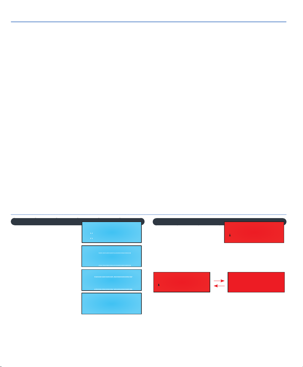
Regen Screen
Displays the time remaining
in the current cycle. 2nd
backwash cycle will flash.
Pressing REGEN advances
to the next cycle.
In Alternator Systems
when a unit is waiting to
initiate the first cycle step
of regeneration, “REGEN
PENDING” is displayed.
“STAND BY” is displayed
in Alternator Systems
when a valve is in Standby
state.
“DELAYED RINSE+FILL” is displayed whenever a
zero-capacity tank has transferred to an off-line state
and is currently waiting to initiate the second portion
of a regeneration cycle. Viewed only when Delayed
Rinse and Fill is set to ON.
Regen & Error Screens
BACKWASH
6:36
MIN2
REGEN PENDING
ALT MAV
STAND BY
AUX MAV
DELAYED RINSE+FILL
PENDING
Error Screens
ERROR Screen displays
when an error occurs and
no Dealer Information is
present. Top line will display specific error while the 3
digits in the lower right side will display specific error
code. Top line error display longer than 18 characters
will scroll across display from right to left.
Alternating ERROR and Dealer Contact Information
will display when an error occurs and Dealer Contact
Information is present.
EEEEEEEEEEEEEEEEEEE
ERROR
ccc
CLOCK NEXT UP DOWN REGEN
PPPPPPPPPPPPPPPPPP
NNNNNNN
TEL
Alternate
EEEEEEEEEEEEEEEEEEE
ERROR
ccc

Nelsen Water Solutions 1", 1¼", 1½", 2" & Twin Control Valves
Press NEXT to return to the
Time of Day screen.
Time of day should only
need to be set after power
outages lasting more than
8 hours, if the battery has
been depleted and a power
outage occurs, or when daylight savings time begins
or ends. If a power outage lasting more than 8 hours
occurs, the time of day will flash on and off which
indicates the time of day should be reset. If a power
outage lasts less than 8 hours and the time of day
flashes on and off, the time of day should be reset
and the battery replaced.
11
Button Operation and Function
Scrolls to the next display.
Pressing once and releasing will schedule
a regeneration at the preset delayed
regeneration time.
Pressing again and releasing will cancel the
regeneration.
Pressing and holding for 3 seconds will initiate an
immediate regeneration.
Pressing while in regeneration will advance to the
next cycle.
Pressing in the program levels will go backwards to
the previous screen.
Changes variable being displayed.
Holding NEXT and REGEN
simultaneously for 3 seconds initiates
a control reset. The software version is
displayed and the piston returns to the
home/service position re-synchronizing the valve.
Used with a twin valve, 1.0T, holding
for at least 3 seconds causes a switch in
the tank in Service without cycling the
regeneration valve. After tank switch, days remaining
and capacity remaining status is retained for each
tank until the next regeneration.
Holding pand qsimultaneously
for 3 seconds while in Control
Programming initiates a master reset.
Resets programming and diagnostic level. Displays
back to factory defaults. Retains current history level
displays.
Press any button to
activate display.
ByPass Operation
Normal Operation
Treated Out Untreated In
Bypass Operation
Untreated Out Untreated In
To shut off water to the system, position arrow
handles as shown in the bypass operation diagram to
the right.
Button Operation & Functions
Press and hold
CLOCK until TIME
HOUR is displayed and the
Hour and AM/PM flashes.
Press por quntil the
correct hour is displayed.
Then press NEXT. The
Minutes will flash. Press p
or quntil the correct minute
is displayed.
Setting Time of Day
TIME HOUR
12:00 PM
TIME MINUTES
12:01 PM
22Nelsen Water Solutions User Guide
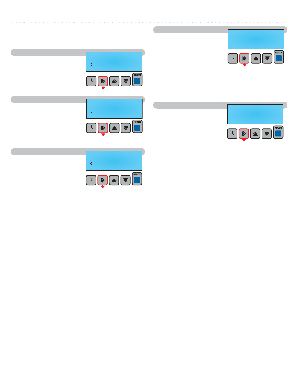
When the system is operating, one of five displays
may be shown. Pressing NEXT will alternate
between the displays shown below.
User 1
Typical user display shows
Time of Day and droplet of
water indicating water flow.
User 2
Shows volume remaining
to regeneration. This screen
will not be viewed if the
control is set for time-clock
operation.
User 3
Displays number of days
to next regeneration. Not
shown when day override
set to off.
User Displays
TIME OF DAY
12:01
PM
CAPACITY REMAINING
1200
GAL
REGENERATION IN
14 DAYS
User 4
Flow Rate displays the
current flow rate of treated
water through the valve. If
Configuration 3CS is set to
ALT A or B and the valve
is in Standby, this display
and the flashing Flow Indicator viewed in other User
Screens will not be viewed.
A Tank In Service Indicator (A or B) is active
whenever 1.0T Mode is set in Configuration 2CS.
User 5
Displays dealer contact
name and number when
programmed in the Installer
Level. Steps 7IL & 8IL.
FLOW RATE
A 0.0
GPM
PPPPPPPPPPPPPPPPPP
NNNNNNN
TEL
33
Nelsen Water Solutions 1", 1¼", 1½", 2" & Twin Control Valves
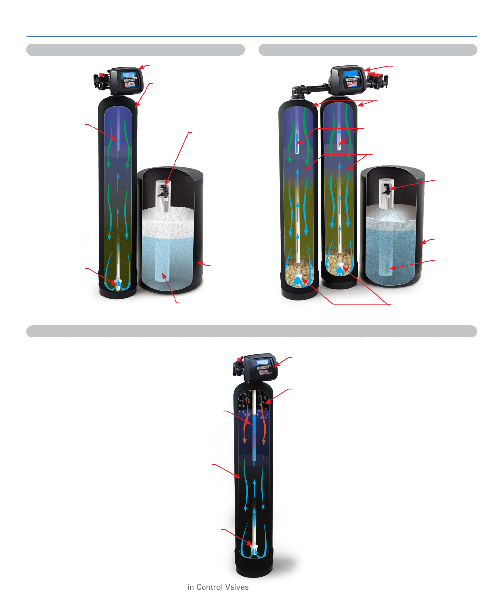
Nelsen Water Systems
Control Valve
Air Pocket
Filter Media
Distributor Tube
Brine
Tank
Control Valve
Softener Tank
Safety
Brine
Valve
Air Check
Ion Exchange Resin
Distributor
Riser Tube Distributor
Riser Tube
Distributor
Basket
Distributor
Basket
Single Tank Softener
Air Injection Oxidation (AIO) Filter System
Control Valve
Softener Tank
Safety
Brine Valve
Air Check
Distributor Basket
Brine
Tank
Twin Tank Softener

44Nelsen Water Solutions User Guide
Maintenance of Your Conditioner
Salt: Salt is vital to your system working correctly.
Not only must a softener have salt, but it should be
the proper type to ensure efficient unit recharging.
Ask your dealer what kind of salt may best suit your
needs. Always have an adequate supply of salt on
hand. Initially, check the salt level of your brine tank
every couple of weeks to determine how much salt
you use - this will depend on how much water you
use. As a rule of thumb, with 20 gpg of hard water,
about 1/2 lb. of salt per person per day is used. In
other words, a family of four uses 60 lbs. of salt a
month. Fill the tank approximately three-fourths full,
with a minimum of 12" of salt. If your household
does not use much water, do not fill your brine tank
over 1/2 full, salt bridging may occur in the brine
tank. This may result in hard water due to ineffective
regeneration. DO NOT USE Block Salt. Block salt
does not dissolve quickly enough to provide proper
regeneration.
Cleaning Brine Tank: The brine tank may require
periodic cleaning. Inspect the brine tank at least
once a year for buildup of insoluble materials. It is
recommended to periodically clean the brine tank no
matter what salt you use. REMEMBER: Salt is the fuel
to run your water conditioner. Buy the best clean
salt available.
Operating Conditions
Your water conditioner has been designed to
adequately handle up to 100 grains per gallon of
hardness and up to 2 ppm of ferrous bicarbonate
iron. This is iron dissolved in water and not visible
to the eye in a freshly drawn sample. After standing
in contact with air, the ferrous iron will oxidize to the
ferric state and start precipitating as a reddish-brown
floc. It can be seen and may cause discolored water.
For your softener to remove the iron, air (oxygen)
must be kept from coming in contact with water
until after it has been passed through the water
conditioner. In some cases, additional equipment
may be required to treat water supplies having
unique characteristics, such as ferric hydroxide iron,
iron bacteria, low pH, unpleasant taste, and odors,
etc. Contact your dealer if any questions should exist.
This water softener is not intended to be used to
treat microbiologically unsafe water or of unknown
quality without adequate disinfection before or after
treatment.
Water Softener Maintenance
55
Nelsen Water Solutions 1", 1¼", 1½", 2" & Twin Control Valves
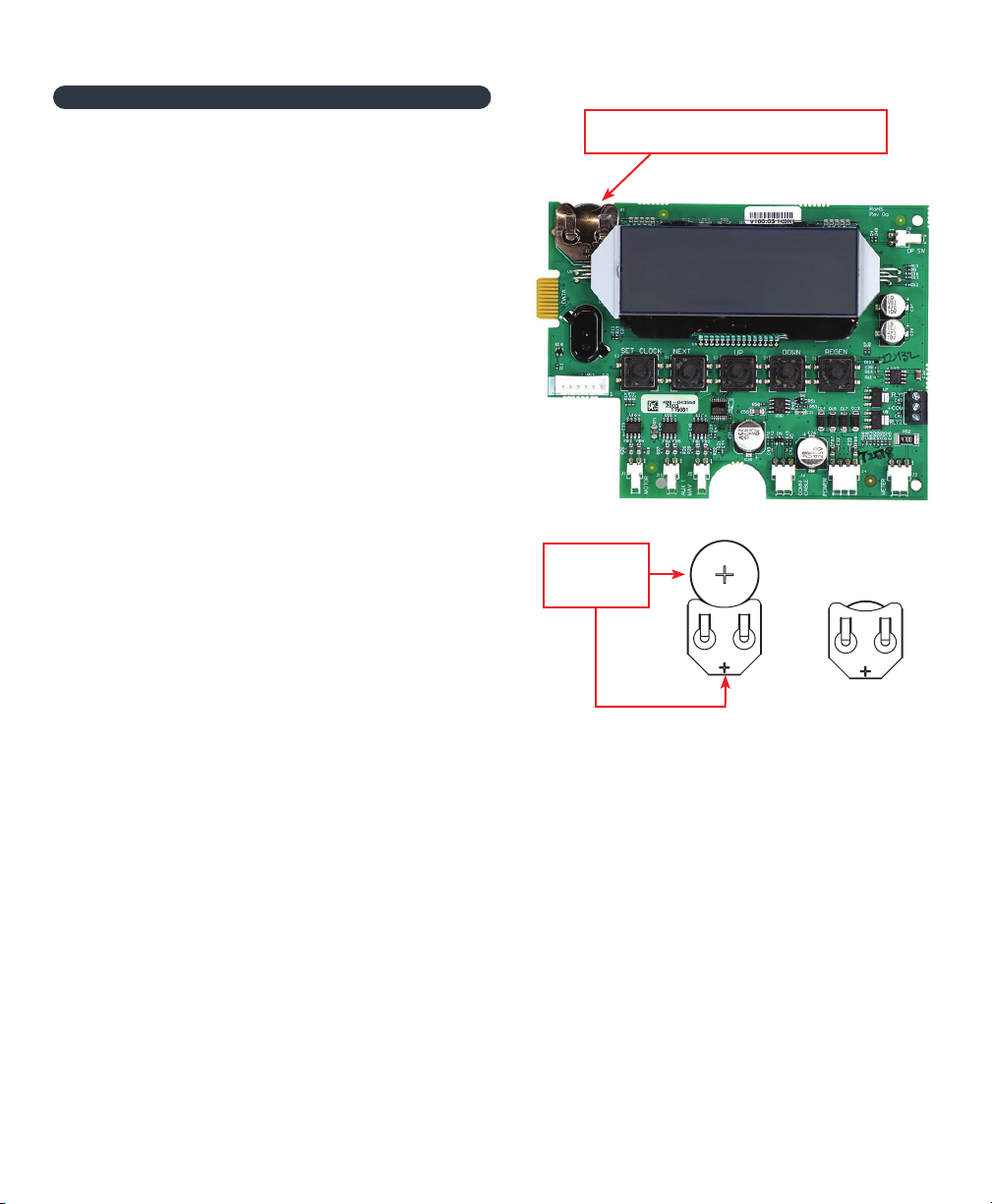
Power Loss and Battery Replacement
If an extended power outage occurs, the control
valve will retain the time-of-day settings until the
board’s battery is depleted. After the battery power
is depleted, the only item that needs to be reset is
the time of day.
Other values are permanently stored in the
nonvolatile memory. The control valve battery is
not rechargeable but is replaceable.
To determine if the battery is depleted:
1. Remove valve cover—disconnect power from PC
Board at the four-pin connector at the bottom of
the board.
2. Wait five minutes for the board to de-energize.
Remove the battery with a non-conductive/
nonmetallic material. Reference the Parts
Breakdown section of this manual for location.
3. Wait five minutes for the board to de-energize.
4. With the battery out, re-connect the power supply
to the board. The board’s display should begin to
show information. This indicates that the board is
operating correctly. If the display does not work,
call installing dealer for service.
5. To replace with a new battery, unplug the
transformer from the outlet. Install a 3-volt Lithium
Coin Cell type 2032 battery, available at most
stores.
Plug the unit back into the outlet.
It is essential to replace the battery with the valve
unplugged to avoid causing a short and potentially
ruining the board.
6. Reset the time of day (see programming
procedures) and initiate regeneration (see
operating displays and maintenance).
Please consult the installing dealer for service if these
procedures do not remedy the problem.
Battery replacement is
3 volt lithium coin cell type 2032.
When replacing
the battery, align
positives and push
down to fully seat.
Fully
Seated
Correct
Battery
Orientation

66Nelsen Water Solutions User Guide
Error Codes
101
UNABLE TO START Valve not sensing valve movement with motor output energized
102
MOTOR STALLED Valve unable to find next cycle position (stalled)
103
MOTOR RAN TOO LONG Valve unable to find next cycle position
104
VALVE HOMING Valve unable to find HOME position
106
ALT MAV RAN TOO LONG Alt MAV motor RAN TOO LONG - unable to find proper park position
107
ALT MAV STALLED Alt MAV motor RAN TOO SHORT, STALLED - unable to find proper park position
109
INVALID MOTOR STATE Control can no longer operate properly due to the detection of an invalid motor
state
116 AUX MAV RAN TOO LONG Aux MAV motor RAN TOO LONG - unable to find proper park position
117 AUX MAV STALLED Aux MAV motor RAN TOO SHORT, STALLED - unable to find proper park
position
201
INVALID REGEN STEP Control can no longer operate properly due to the detection of an invalid
regeneration cycle step - Internal Software Error
202
UNEXPECTED STALL Motor encountered an unexpected stall but was able to recover from and proceed
normally
402
POWER DOWN MEMORY Control can no longer operate properly due to a check sum error for the Operational
Data and Status Section of E
2
PROM memory
403
PROGRAM MEMORY Control can no longer operate properly due to a check sum error for the
Programming Section of E
2
PROM memory
404
DIAGNOSTIC MEMORY Control can no longer operate properly due to a check sum error for the Diagnostic
Section of E
2
PROM memory
405
HISTORY MEMORY Control continues to operate normally w/check sum error for the History Section of
E
2
PROM memory, however error is recorded in Error Log
406
CONTACT MEMORY Control can no longer operate properly due to a check sum error for the Contact
Screen Section of E
2
PROM memory
407
STATUS RAM
STATUS RAM MEMORY FAILURE - Error generated when the microcontroller can't
operate properly due to corrupted data contained in the Operational Data/Status
Section of RAM memory. When this error is generated, like a "405" or "408" Error,
a "407" is recorded in the Error Log, but the control does not enter Error Mode and
continues to operate normally using previously stored Status RAM data (that can be
up to 6 hrs. old). This portion of memory includes the state of motors, relays, flow,
regen, and more. Most things that are tracked on a moment-by-moment basis that
need to be able to recover in the event of a power loss or reset is saved here.
408
DIAGNOSTIC RAM
DIAGNOSTIC RAM MEMORY FAILURE - Error generated when the microcontroller
can't operate properly due to corrupted data contained in the Diagnostic Section
of RAM memory. When this error is generated, like a "405" or "407" Error, a "408" is
recorded in the Error Log, but the control does not enter Error Mode and continues
to operate normally using previously stored Diagnostic RAM data (that can be up to
6 hrs. old). This portion of memory includes parameters normally displayed in the
diagnostic branch of the menu map.
410
CONFIG DOWNLOAD Configurator file downloaded to the control was not originally uploaded from
another control with the identical software revision
Error Description of Error

77
Nelsen Water Solutions 1", 1¼", 1½", 2" & Twin Control Valves
Troubleshooting
No Display on PC Board
No power at electric outlet Repair outlet or use working outlet
Control valve power adapter is not plugged
into outlet or power cord end is not con-
nected to PC board connection
Plug Power Adapter into outlet or connect power cord
end to PC Board connection
Improper power supply Verify proper voltage is being delivered to PC Board
Improper power supply Replace power adapter
Defective PC Board Replace PC Board
PC Board does not dis-
play correct time of day
Power Adapter plugged into electric outlet
controlled by light switch Use uninterrupted outlet
Tripped breaker switch and/or tripped GFI Reset breaker switch and/or GFI
Power outage
Reset time of day. If PC Board has battery back up pres-
ent the battery may be depleted. See front cover and
drive assembly drawing for instructions
Defective PC Board Replace PC Board
Display does not
indicate that water is
flowing. (Refer to user
instructions for how the
display indicates water
is flowing)
Bypass valve is in bypass position Turn bypass handles to place bypass in service position
Meter is not connected to meter connec-
tion on PC Board
Connect meter to three pin connection labeled METER
on PC Board
Restricted/stalled meter turbine Remove meter and check for rotation or foreign material
Meter wire is not installed securely into
three pin connector
Verify meter cable wires are installed securely into three
pin connector labeled METER
Defective meter Replace meter
Defective PC Board Replace PC Board
Control valve
regenerates at wrong
time of day
Power outage
Reset time of day. If PC Board has battery back up
present the battery may be depleted. See front cover
and drive assembly drawing for instructions
Time of day is not set correctly Reset to correct time of day
Time of regeneration is set incorrectly Reset regeneration time
None of the Above Call Dealer for further troubleshooting
Time of day flashes on
and off Power outage
Reset time of day. If PC Board has battery back up pres-
ent the battery may be depleted. See front cover and
drive assembly drawing for instructions
Control valve does not
regenerate automati-
cally when the REGEN
button is pressed and
held
Broken drive gear or drive cap assembly Replace drive gear or drive cap assembly
Broken piston rod Replace piston rod
Defective PC Board Defective PC Board
Control valve does not
regenerate automati-
cally but does when
the REGEN button is
pressed and held
Bypass valve is in bypass position Turn bypass handles to place bypass in service position
Meter is not connected to meter connec-
tion on PC Board
Connected meter to three pin connection labeled METER
on PC Board
Restricted/stalled meter turbine Remove meter and check for rotation or foreign material
Incorrect programming Check for programming error
Meter wire is not installed securely into
three pin connector
Verify meter cable wires are installed securely into three
pin connector labeled METER
Defective meter Replace meter
Defective PC Board Replace PC Board

88Nelsen Water Solutions User Guide
Troubleshooting
Hard or untreated water
is being delivered
Bypass valve is open or faulty Fully close bypass valve or replace
Media is exhausted due to high water
usage Check diagnostics for abnormal water usage
Media is exhausted due to high water
usage Remove meter and check for rotation or foreign material
Meter not registering Test water and adjust program values accordingly
Water quality fluctuation Add proper salt to tank
No brine or low level of brine in brine tank Refer to Control valve fails to draw in brine below
Control fails to draw in brine Check refill setting in programming. Check refill flow
control for restrictions or debris and clean or replace
None of the above Call your Water Treatment Dealer
Control valve uses too
much brine
Improper refill setting Check refill setting
Improper program settings Check program setting to make sure they are specific to
the water quality and application needs
Control valve regenerates frequently Check for leaking fixtures that may be exhausting
capacity or system is undersized
Residual brine being
delivered to service
Low water pressure Check incoming water pressure - water pressure must
remain at minimum of 25 psi
Incorrect injector size Replace injector with correct size for the application
Restricted drain line Check drain line for restrictions or debris and clean
Excessive water in brine
tank
Improper program settings Check refill setting
Plugged injector Remove injector and clean or replace
Drive cap assembly not tightened in
properly Re-tighten the drive cap assembly
Damaged seal/stack assembly Replace seal/stack
Restricted or kinked drain line Check drain line for restrictions or debris and or un-kink
drain line
Plugged backwash flow controller Remove backwash flow controller and clean or replace
Missing refill flow controller Replace refill flow controller
Control valve fails to
draw in brine
Injector is plugged Remove injector and clean or replace
Faulty brine piston Replace brine piston
Brine line connection leak Inspect brine line for air leak
Drain line restriction or debris cause
excess back pressure Inspect drain line and clean to correct restriction
Drain line too long or too high Shorten length and or height
Low water pressure Check incoming water pressure - water pressure must
remain at minimum of 25 psi
Water running to drain
Power outage during regeneration Upon power being restored control will finish the re-
maining regeneration time. Reset time of day
Damaged seal/stack assembly Replace seal/stack assembly
Piston assembly failure Replace piston assembly
Drive cap assembly not tightened properly Re-tighten the drive cap assembly

99
Nelsen Water Solutions 1", 1¼", 1½", 2" & Twin Control Valves
Limited Warranty
NELSEN CORPORATION - NWS WATER CONDITIONER
Nelsen Corporation (“Nelsen”) provides this limited warranty as described below (the “Limited Warranty”).
Limited Warranty - Subject to the terms of this Limited Warranty, Nelsen warrants to the original buyer (“Buyer”) of this Water
Conditioner product (the “Product”) solely from a Nelsen authorized dealer that the Product will be free from defects in material or
workmanship for a period of one (1) year after the date of original installation. This Limited Warranty shall apply only if the Product is
installed, operated and maintained in strict accordance with Nelsen’s or the manufacturer’s guidelines and other legal requirements.
The Product is sold with the understanding that Buyer has independently determined the suitability and compatibility of such Product
for Buyer’s purposes. Any statements, technical information or recommendations concerning the Product or any parts therein by
Nelsen are based upon data provided to Nelsen by its suppliers and believed to be accurate, but do not constitute a guarantee or
warranty. This Limited Warranty shall not cover and shall be null and void if, in Nelsen’s discretion, the Product, or any parts therein,
are: (a) manufactured by a third party manufacturer; (b) modified after sale or use of replacement parts not specified by manufacturer
requirements; (c) improperly installed, stored, used, operated, handled or maintained; or (d) abused, misused or otherwise damaged
for any reason, including due to negligence, weather, fire, lightning, power surges or other acts of God or exposure to freezing or hot
water or the effects of normal wear and tear.
Third Party Warranties - In lieu of the above Limited Warranty, the Product, or any parts therein, may be covered by a third-party
manufacturer’s warranty. Nelsen’s authorized dealer will provide Buyer with a copy of any third-party manufacturer warranty prior
to purchase. Nelsen shall transfer and assign to Buyer any and all third-party manufacturer’s warranties on the Product, or any parts
therein, subject to the conditions and exclusions in the manufacturer’s warranty. Buyer’s exclusive remedy under such third-party
manufacturer’s warranty shall be against such third-party manufacturer and not Nelsen. Buyer may need to register the Product with a
third party manufacturer in order to obtain its warranty.
Additional Conditions -
• This Limited Warranty only covers the Product, and any parts therein, if used exclusively for residential purposes in a single-
family dwelling. This limited warranty shall be null and void if the Product is used for commercial, industrial or other non-residential
applications.
• This Limited Warranty will not cover any Product used for outdoor installations unless a weather cover that complies with
manufacturer requirements is utilized.
• This Limited Warranty shall not cover the Product if operated at water pressures or water temperatures or with water contaminants
that exceed manufacturer’s guidelines.
• The Product may include interconnecting piping that may have leaks, even if tested at the time of manufacture, due to pipe
vibrations and handling. For example, galvanized pipe threads are diligently assembled with recommended thread sealants but may
have leaks discovered at the time of installation or start-up. The installer of the goods is responsible for checking the system for leaks
upon start-up and making any repairs if necessary.
• This Limited Warranty does not cover damage or failure of the Product, or any part therein, caused by friction, wear, chemical
attack or debris build-up on wear parts. For purposes hereof, “wear parts” shall include, without limitation, pistons, piston rods, seals,
spacers, end cap quad rings, brine valves, valve disk flappers and parts requiring replacement under recommended maintenance
procedures, including, without limitation, o-rings and gaskets.
Warranty Claims - All claims under this Limited Warranty shall be submitted by Buyer to the authorized Nelsen dealer who sold the
Product in writing and shall include the Buyer’s name, address, telephone number, date of purchase of the Product, receipt evidencing
proof of purchase and a copy of this Limited Warranty. Nelsen or its authorized dealer will investigate the claim. Buyer must fully
cooperate in investigating and evaluating the claim, including, without limitation, providing additional information upon request. TO BE
ELIGIBLE FOR COVERAGE UNDER THIS LIMITED WARRANTY, BUYER MUST SUBMIT A CLAIM WITHIN SIXTY (60) DAYS OF THE DATE
THAT THE ALLEGEDLY DEFECTIVE PRODUCT OR PART IS FIRST DISCOVERED BY BUYER AND, IN NO EVENT, LATER THAN SIXTY (60)
DAYS AFTER THE WARRANTY PERIOD HEREIN.
Repair or Replacement/Credit - Subject to the conditions and limitations herein, if Nelsen determines that the Product, or any part
therein, does not conform to this Limited Warranty, Nelsen will repair or replace the defective Product or part therein. Non-conforming
Products or parts therein must be returned to Nelsen’s authorized dealer at Buyer’s cost. Any replaced Products, or any parts therein,
shall be retained by and become the property of Nelsen. If Nelsen determines that the repair or replacement of the Product or part
Continued Next Page

©Nelsen CorporationPart No: NWS USER GUIDE
therein is not commercially practicable, Nelsen will issue a credit in favor of Buyer in an amount not to exceed the purchase price of
the Product. Notwithstanding anything to the contrary herein, this Limited Warranty does not cover any cost or labor associated with
the removal or re-installation of the replacement Product or part therein or any shipping costs associated with the returned Product or
part therein, which remains the sole cost, risk and responsibility of Buyer, unless otherwise agreed in writing by Nelsen.
Eligibility/Non-Transferable - This Limited Warranty applies only to Buyer if the Product is purchased from a Nelsen authorized dealer.
This Limited Warranty is personal to Buyer and may not be assigned or otherwise transferred by Buyer. Any attempt to transfer this
Limited Warranty shall be null and void and not recognized by Nelsen.
Disclaimer of Other Warranties/Limitation on Liability
EXCEPT AS PROVIDED ABOVE AND TO THE EXTENT PERMITTED BY LAW, THERE ARE NO OTHER REPRESENTATIONS OR
WARRANTIES WITH RESPECT TO THE PRODUCT, EITHER EXPRESSED OR IMPLIED, WRITTEN OR ORAL, OR ARISING UNDER
CUSTOM OF TRADE, INCLUDING, WITHOUT LIMITATION, THE IMPLIED WARRANTIES OF MERCHANTABILITY AND FITNESS
FOR A PARTICULAR PURPOSE. NO REPRESENTATIONS OR WARRANTIES AT ANY TIME MADE BY ANY EMPLOYEE, AGENT OR
REPRESENTATIVE OF NELSEN SHALL BE EFFECTIVE TO VARY OR EXPAND ANY WRITTEN WARRANTY OR THE TERMS HEREOF. TO
THE EXTENT A WAIVER OF IMPLIED WARRANTIES IS PROHIBITED BY LAW, ANY IMPLIED WARRANTIES SHALL BE LIMITED TO THE
DURATION OF ANY WRITTEN WARRANTY PROVIDED BY NELSEN.
IN NO EVENT SHALL NELSEN BE LIABLE TO BUYER OR TO ANY THIRD PARTY FOR CONSEQUENTIAL, INCIDENTAL, SPECIAL OR
PUNITIVE DAMAGES, OR FOR LOST PROFITS OR LOSS OF USE, RESULTING FROM OR IN ANY MANNER RELATED TO THE PRODUCT,
ITS DELIVERY, NON-DELIVERY, USE, OR INABILITY TO USE THE SAME, WHETHER SUCH DAMAGES BE CLAIMED UNDER CONTRACT,
TORT OR ANY OTHER LEGAL THEORY.
NELSEN’S TOTAL LIABILITY UNDER THIS OR ANY OTHER WARRANTY, EXPRESS OR IMPLIED, IS LIMITED TO REPAIR OR
REPLACEMENT OF, OR CREDIT FOR, THE PRODUCT OR ANY PART, AS STATED HEREIN.
Waiver of Class Action
ANY AND ALL CLAIMS ASSERTED BY BUYER OR ANY OTHER PERSON OR ENTITY SHALL BE RAISED IN AN INDIVIDUAL CAPACITY
AND NOT AS A PLAINTIFF OR CLASS MEMBER IN ANY PURPORTED CLASS OR REPRESENTATIVE PROCEEDING, WHICH ARE HEREBY
WAIVED.
Applicable Law - This Limited Warranty shall be interpreted and governed under the laws of the State of Ohio without giving effect
to the choice of law rules thereof. Nelsen and Buyer irrevocably consent and submit to the exclusive jurisdiction and venue within the
courts of Summit County, Ohio and/or the United States District Court for the Northern District of Ohio in connection with any litigation
arising out of, or in any way relating to, this Limited Warranty or the Product, including, but not limited to, any and all claims for breach
of warranty or products liability, and Nelsen and Buyer expressly waive any objection to the jurisdiction and/or venue of such courts.
Limited Warranty
This manual suits for next models
3
Other NELSEN WATER Water Filtration System manuals

Popular Water Filtration System manuals by other brands


Savillex
Savillex DST-1000 Upgrade instructions

Pure Company
Pure Company Carbon Filter Water Decanter instructions

Evolution Aqua
Evolution Aqua EAZYPOD AUTOMATIC Installation and instruction manual

SPX FLOW
SPX FLOW ME Series instruction manual

Puretec
Puretec Basic HD Series user guide

Bio-Tek
Bio-Tek Biolux HOS Series owner's manual

Waterco
Waterco HYDROCHLOR MK3 owner's manual

FLORABEST
FLORABEST FGPZ 12 A1 Operation and safety notes

Bluewater
Bluewater Pro Series owner's manual

Eco Pure
Eco Pure ECOP20 Installation and operation manual

Plasma Made
Plasma Made GUC 1214 Installation and user manual

Clear Water
Clear Water FS016 owner's manual