manuals.online logo
Brands
  1. Home
  2. •
  3. Brands
  4. •
  5. Nelson
  6. •
  7. Irrigation System
  8. •
  9. Nelson SRNV100 User manual

Nelson SRNV100 User manual

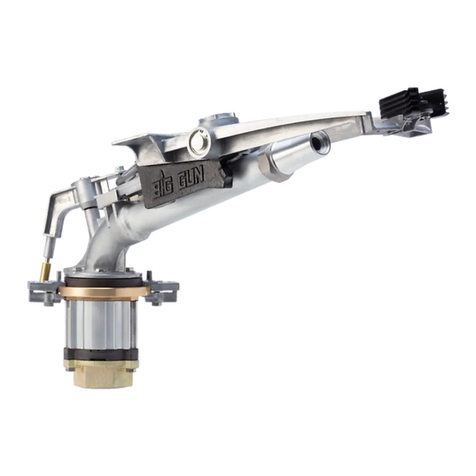
SRNV100 BIG GUN® OPERATION AND ADJUSTMENT INSTRUCTIONS
Nelson Irrigation Corporation 848 Airport Road Walla Walla, WA 99362-2271 USA el: 509.525.7660 Fax: 509.525.7907 E-mail: [email protected] Web site: www.nelsonirrigation.com
SET UP FOR OPERATION:
1. Install 100T taper bore nozzle or
100R ring nozzle. The SRNV100 is
not designed to operate with the
100TR taper ring nozzle. If using the
ring nozzle set, install desired ring size
in the ring nozzle cap. The ring nozzle
cap can be sufficiently tightened by
hand. NOTE: If the 100R is used, it is
supplied with the ring cap, part number
7872. If any other cap is used, the
nozzle al e will not completely close.
. To install the SRNV100, orient the
lower unit so the solenoid or hose
bracket will be located on the right
when viewed from the rear of the Big
Gun looking downstream.
3. Adjust location of stops to give desired
arc of coverage. Stops must be mounted
so that the arrows point toward each
other and the trip lever is located between
the arrows. If the stops are reversed on
the wrong end of the arc then the Big
Gun will fail to reverse.
4. The SRNV100 is factory set for normal
rotation speed. If a faster or slower
rotation speed is desired, move the arm
weight backward for faster operation
or forward for slower operation. The
SR100 low pressure drive vane kit,
part number 9857, is available to
enhance the drive when operating in
a nozzle range of .5-.65 100T and
pressure below 60 psi. NOTE: If the
SRNV100 is mounted on a tilted riser
of 10 degrees (or 17% slope) or more,
a 100CBK counter balance kit is
recommended to pre ent back-
sliding and impro e proper rotation
throughout the entire arc setting.
OA-SRNV100-2 8/01
SRNV100 BIG GUN®
WARRANTY AND DISCLAIMER
Nelson Big Gun® Sprinklers are warranted or one year rom date o original sale to be ree o de ective materials and workmanship when used within the working
speci ications or which the product was designed and under normal use and service. The manu acturer assumes no responsibility or installation, is limited solely to
replacement or repair o de ective parts, and the manu acturer will not be liable or any crop or other consequential damages resulting rom any de ects or breach o
warranty. THIS WARRANTY IS EXPRESSLY IN LIEU OF ALL OTHER WARRANTIES, EXPRESS OR IMPLIED, INCLUDING THE WARRANTIES OF MERCHANTABILITY AND
FITNESS FOR PARTICULAR PURPOSES AND OF ALL OTHER OBLIGATIONS OR LIABILITIES OF MANUFACTURER. No agent, employee or representative o the manu acturer
has authority to waive, alter or add to the provisions o the warranty, nor to make any representations or warranty not contained herein. This product may be covered
by one or more o the ollowing U.S. Patent Numbers 3,744,720 and 3,559,887 and other U.S. Patents pending or corresponding issued or pending oreign patents.
5. If installing the SRNV100E (with solenoid), connect the solenoid wires to the
proper voltage source. Energizing the solenoid with the proper voltage results
in the valve opening. If installing the SRNV100H hydraulically controlled
(without solenoid), connect the actuator feed hose to the appropriate control
pressure circuit. Application of hydraulic pressure (equal to or greater than
SRNV100 base water pressure) to the actuator causes the nozzle valve to
close. If actuator control pressure (line pressure) is approximately 0 psi or
below, low pressure SRNV closure kit, part number 99 4, is recommended to
provide reliable operation.
6. Be sure the entire control system is operating properly and that the hydraulic
fittings are securely installed. Failure to do so could prevent the nozzle valve
from closing, possibly causing personal injury or property damage. Observe
an entire opening-closing-opening cycle for proper operation.
WARNING!
1. Read operating instructions before operating sprinkler or making any
adjustments.
. Never make adjustments or perform service while sprinkler is in operation.
3. Stand clear of high velocity water stream.
4. Never direct water stream onto roadway or electrical transmission lines.
5. Stay clear of nozzle valve linkage during operation. High clamping forces exist.
6. Stand clear of sprinkler during operation. Abrupt water spray exists during
opening and closing of valve.
7. To avoid injury or damage, check for proper operation of control system
before using nozzle valve.
Trip Lever
Shift Lever
Arm Weight
Drive Arm
Nozzle
Actuator Feed Hose
Solenoid
Drive Vane
Nozzle Lever
Toggle Linkage
Actuator
Valve Seat
Nelson Irrigation Corporation 848 Airport Road Walla Walla, WA 99362-2271 USA el: 509.525.7660 Fax: 509.525.7907 E-mail: [email protected] Web site: www.nelsonirrigation.com
SRNV100 BIG GUN® ADJUSTMENT
8/01
item part number description qty.
18506 Nut, 7/16-14 UNC 1
28469 Valve Seat Assembly 1
38510 Nozzle Leve Assembly 1
46124 Cotte Pin, 3/32 x 3/4 8
57263 Pivot Pin 1
66110 Flat Washe AR
76110-001 Flat Washe (Thick) AR
87264 Lowe Toggle Pin 1
97265 Uppe Toggle Pin 1
10 7719 Linkage Assembly 1
11 7297 Actuato Pin 1
12 7296 Jam Nut 1
13 7797 Washe 1
14 7276 Actuato Assembly 1
PROBLEM: Nozzle stopper (valve seat) continues to leak when closed.
SOLUTION: 1. Adjust valve seat to assu e even contact on nozzle seal su face.
a. Disconnect actuato pin .
b. Loosen the valve seat locking nut .
c. Rotate leve assembly to closed position and hold valve seat
lightly against nozzle seal su face. Adjust valve seat by otating the
stoppe in o out as equi ed to achieve full contact with the nozzle seal su face.
d. Tighten the locking nut .
2. Adjust linkage to assu e adequate closu e fo ce.
a. Adjust linkage assembly at A so that 12-15 pounds fo ce is equi ed to
push link B against closu e stop (disconnect and econnect lowe toggle
pin du ing adjustment as equi ed to check closu e).
b. Reconnect actuato pin .
PROBLEM: Nozzle stopper wont clear stream when open.
SOLUTION: Adjust actuato position to assu e complete opening.
a. Loosen jam nut .
b.Hold nozzle leve in the fully open est position.
c. Rotate actuato assembly towa d main elbow until est buttons contact
and all play is emoved f om the linkage. Rotate fu the as needed until
d ain hole and hose fitting po t a e o iented to the bottom.
d. Tighten jam nut .

This manual suits for next models

1

Other Nelson Irrigation System manuals

Nelson F75 Big Gun Instruction Manual

Nelson

Nelson F75 Big Gun Instruction Manual

Nelson ROTATOR R2000WF User manual

Nelson

Nelson ROTATOR R2000WF User manual

Nelson R55VT User manual

Nelson

Nelson R55VT User manual

Nelson 3000 Series User manual

Nelson

Nelson 3000 Series User manual

Nelson RainTrain2 User manual

Nelson

Nelson RainTrain2 User manual

Nelson PC-S3000 User manual

Nelson

Nelson PC-S3000 User manual

Nelson R75 Installation guide

Nelson

Nelson R75 Installation guide

Nelson Traveling Sprinkler User manual

Nelson

Nelson Traveling Sprinkler User manual

Nelson BIG GUN 75 Series User manual

Nelson

Nelson BIG GUN 75 Series User manual

Nelson F44AAB User manual

Nelson

Nelson F44AAB User manual

Nelson R55 User manual

Nelson

Nelson R55 User manual

Nelson PRO 6000 Guide

Nelson

Nelson PRO 6000 Guide

Popular Irrigation System manuals by other brands

Irritrol 450R Setting instructions

Irritrol

Irritrol 450R Setting instructions

Komet Twin Series Technical manual

Komet

Komet Twin Series Technical manual

Rain Bird 552 Series Operation & maintenance manual

Rain Bird

Rain Bird 552 Series Operation & maintenance manual

Tyco Fire Product CENTRAL H-1 instruction manual

Tyco Fire Product

Tyco Fire Product CENTRAL H-1 instruction manual

Munters Green Field DC user manual

Munters

Munters Green Field DC user manual

CENTRAL tyco CHEC quick start guide

CENTRAL

CENTRAL tyco CHEC quick start guide

Hunter PGJ quick start guide

Hunter

Hunter PGJ quick start guide

Eden 96215EDAMZ instructions

Eden

Eden 96215EDAMZ instructions

Rain Bird T-Bird T-22 installation instructions

Rain Bird

Rain Bird T-Bird T-22 installation instructions

Viking MICROFAST M-4 Technical data

Viking

Viking MICROFAST M-4 Technical data

Tyco FTR-1 manual

Tyco

Tyco FTR-1 manual

Viking 300TB-IP product manual

Viking

Viking 300TB-IP product manual

Autopot 4Pot XL Set-up guidelines

Autopot

Autopot 4Pot XL Set-up guidelines

Johnson Controls tyco RFII manual

Johnson Controls

Johnson Controls tyco RFII manual

Tyco Fire Product CENTRAL BV4 instruction manual

Tyco Fire Product

Tyco Fire Product CENTRAL BV4 instruction manual

Rain Bird T-Bird T-22 installation instructions

Rain Bird

Rain Bird T-Bird T-22 installation instructions

Tyco rapid response LFII Series manual

Tyco

Tyco rapid response LFII Series manual

Galcon 9001D Operation and installation instructions

Galcon

Galcon 9001D Operation and installation instructions

manuals.online logo
manuals.online logoBrands
  • About & Mission
  • Contact us
  • Privacy Policy
  • Terms and Conditions

Copyright 2025 Manuals.Online. All Rights Reserved.