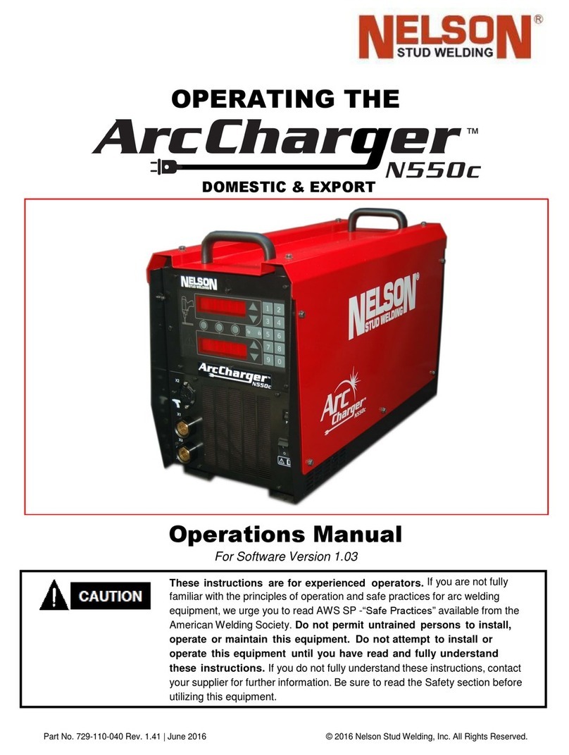
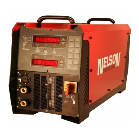
Nelson N1500i User manual

Part No. 729-110-053 V.1.03 © 2018 Nelson Stud Welding, Inc. All rights reserved.
Operating the N1500i FACS Stud
Welding System
Operations Manual
(729-110-053)
For Dot Matrix Units Software Version 1.00 and later
These instructions are for experienced
operators.
If you are not fully familiar with
the principles of operation and safe practices for arc welding equipment, we urge you
to read AWS SP -“Safe Practices” available from the American Welding Society. Do not
permit untrained persons to install, operate or maintain this equipment. Do
not
attempt to install or operate this equipment until you have read and fully
understand
these
instructions.
If you do not fully understand these instructions,
contact your supplier for further information. Be sure to read the Safety section before
utilizing this equipment. .

Part No. 729-110-053 V.1.03 © 2018 Nelson Stud Welding, Inc. All rights reserved.
INVERTER LIMITED WARRANTY
Nelson’s only warranty is that goods being sold will be free from defects in workmanship and
material. This warranty is expressly in lieu of other warranties, expressed or implied and
whether statutory or otherwise, including any implied warranty of merchantability or fitness for
a particular purpose.
Nelson’s liability for breach of warranty shall arise only upon return of the defective goods at
Buyer’s expense after notice to Nelson of the claimed breach, and shall be limited to furnishing
a like quantity of such goods free from such defects or, at Nelson’s option, to refunding the
purchase price (less reasonable depreciation based on actual use); provided, however, that
Nelson will not accept receipt of equipment returned unless buyer has previously afforded
Nelson’s personnel a reasonable opportunity to inspect and repair said equipment at buyer’s
facility or such other location as is mutually agreeable. Notice to Nelson must be given within
30 days of such defect or failure and within two years or one million welds from the date the
equipment was delivered, whichever comes first. No compensation or reimbursement for
transportation costs of any kind will beallowed.
Please note that this warranty does not extend beyond the original registered purchaser, and
does not warrant equipment that has been modified by any party other than Nelson, or
equipment that has been improperly installed, improperly operated, or misused based upon
industry standards, or equipment which hasnot had reasonable and necessary maintenance,
or equipment which has been used for operation outside of specifications for the equipment.
Nelson shall never be liable for consequentialdamages.
Nelson reserves the right to make engineering and/or part changes, at any time without notice,
as a result of our commitment to continuous improvement.

Part No. 729-110-053 V.1.03 © 2018 Nelson Stud Welding, Inc. All rights reserved.
WARNING
The following Safety section is for your
protection. It summarizes precautionary
information from the references listed in the
Additional Safety Information section. Before
performing any installation or operating
procedures, be sure to read and follow the safety
precautions listed below as well as all other
manuals, material safety data sheets, labels, etc.
Failure to observe these precautions can result in
injury or death.
PROTECT YOURSELF AND OTHERS
Some welding, cutting, and gouging processes
are noisy and require ear protection. The arc,
like the sun, emits ultraviolet (UV) rays and
other radiation which can harm the skin and
eyes. Hot metal can cause burns. Training in
the proper use of the processes and equipment
is essential to prevent accidents. Therefore:
1.
Always wear safety glasses with side shields in any work
area, even if welding helmets, face shields and goggles
are also required.
2.
Use a face shield fitted with filter shade #3 per ANSI
Z87.1. Cover sparks and rays of the arc when operating or
observing operations. Warn bystanders not to watch the
arc and not to expose themselves to the rays of the
electric-arc or hot metal.
3.
Wear flameproof gauntlet type gloves, heavy long-sleeve
shirt, cuff-less trousers, high topped shoes, and a welding
helmet or cap for hair protection, to protect against arc
rays and hot sparks or hot metal. A flameproof apron may
also be desirable as protection against radiated heat and
sparks.
4.
Hot sparks or metal can lodge in rolled up sleeves, trousers
cuffs or pockets. Sleeves and collars should be kept
buttoned, and open pockets eliminated from the front of
clothing.
5.
Protect other personnel from arc rays and hot sparks with
suitable nonflammable partitions or curtains.
6.
Use goggles over safety glasses when chipping slag or
grinding. Chipped slag may be hot and can fly far.
Bystanders should also wear goggles over safety glasses.
FIRES AND EXPLOSIONS
Heat from flames and arcs can start fires. Hot
slag or sparks can also cause fires and
explosions. Therefore:
1.
Remove all combustible materials well away from the work
area or cover the materials with a protective
nonflammable covering. Combustible materials include
wood, cloth, sawdust, liquid and gas fuels, solvents, paints
and coatings, paper, etc.
2.
Hot sparks or hot metal can fall through cracks or crevices
in floors or wall openings and cause a hidden smoldering
fire or fires on the floor below. Make certain that such
openings are protected from hot sparks and metal.
3.
Do not weld, cut, or perform other hot work until the work
piece has been completely cleaned so that there are no
substances on the work piece which might produce
flammable or toxic vapors. Do not do hot work on closed
containers. They may explode.
4.
Have appropriate fire extinguishing equipment handy for
instant use, such as a garden hose, water pail, sand bucket
or portable fire extinguisher. Be sure you are trained for
proper use.
5.
Do not use equipment beyond its ratings. For example,
overloaded welding cable can overheat and create a fire
hazard.
6.
After completing operations, inspect the work area to make
certain there are no hot sparks or hot metal which could
cause a later fire. Use fire watchers when necessary.
7.
For additional information, refer to NFPA Standard 51B,
“Fire Prevention in Use of Cutting and Welding Processes,”
available from the National Fire Protection Association,
Batterymarch Park, Quincy, MA 02269
ELECTRICAL SHOCK
Contact with live electrical parts and ground
can cause severe injury or death. DO NOT use
welding current in damp areas, if movement
is confined, or if there is danger of falling.
Therefore:
1.
Be sure the power source frame (chassis) is connected
to the ground system of the input power.
2.
Connect the work piece to a good electrical ground.
3.
Connect the work cable to the work piece. A poor or
missing connection can expose you or others to a fatal
shock.
4.
Use well-maintained equipment. Replace worn or
damaged cables..
5.
Keep everything dry, including clothing, work area,
cables, torch/electrode holder and power source.
6.
Make sure that all parts of your body are insulated from
work and from the ground.
7.
Do not stand directly on metal or the earth while working
in tight quarters or a damp area; stand on dry boards or
an insulating platform and wear rubber soled shoes.
8.
Put on dry, hole-free gloves before turning on the power.
9.
Refer to ANSI/ASC Standard Z49.1 for specific grounding
recommendations. Do not mistake the work lead for a
ground cable.
ELECTRICAL AND MAGNETIC FIELDS
Electric and magnetic fields may be
dangerous. Electric current flowing through
any conductor causes localized Electric and
Magnetic Fields (EMF). Welding and cutting
current creates EMF around welding cables
and welding machines. Therefore:
1.
Operators having pacemakers should consult their
physician before welding. EMF may interfere with some
pacemakers.
2.
Exposure to EMF may have other health effects which
are unknown.
3.
Operators should use the following procedures to
minimize exposure to EMF:
a.
Route the electrode and work cables together. Secure
them with tape when possible.
b.
Never coil the torch or work cable around your body.
c.
Do not place your body between the torch and work
cables. Route cables on the same side of your body.
d.
Connect the work cable to the work piece as close as
possible to the area being welded.
e.
Keep welding power source and cables as far away
from your body as possible.
FUMES AND GASES
Fumes and gases can cause discomfort or
harm, particularly in confined spaces. Do not
breathe fumes and gases. Shielding gases
can cause asphyxiation. Therefore:
1.
Always provide adequate ventilation in the work area by
natural or mechanical means. Do not weld, cut, or
gouge on materials such as galvanized steel, stainless
steel, copper, zinc, lead, beryllium, or cadmium unless
positive mechanical ventilation is provided. Do not
breathe fumes from these materials.
2.
Do not operate near degreasing and spraying
operations. The heat or arc rays can react with
chlorinated hydrocarbon vapors to form phosgene, a
highly toxic gas, and other irritant gasses.
3.
If you develop momentary eye, nose, or throat irritation
while operating, this is an indication that ventilation is
not adequate. Stop work and take necessary steps to
improve ventilation in the work areas. Do not continue
to operate if physical discomfort persists.
4.
Refer to ANSI/ASC Standard Z49.1 (see listing on next
page) for specific ventilation recommendations.
Part No. 729-110-053 V.1.03 © 2018 Nelson Stud Welding, Inc. All rights reserved.
ELECTRICALLY POWERED EQUIPMENT
Faulty or improperly electrified equipment
can cause injury or death. Therefore:
1.
Always have qualified personnel perform the installation,
troubleshooting, and maintenance work. Do not perform
any electrical work unless you are qualified to perform
such work.
2.
Before performing any work inside a power source,
disconnect the power source from the incoming electrical
power using the disconnect switch at the fuse box before
working on the equipment.
3.
Install equipment in accordance with the U.S. National
Electrical Code, all local codes and the manufacture’s
recommendations.
4.
Ground the equipment in accordance with the U.S.
National Electrical Code and the manufacturer’s
recommendations.
CYLINDER HANDLING
Cylinders, if mishandled, can rupture and
violently release gas. Sudden rupture of
cylinder, valve, or relief device can injure or
kill. Therefore:
1.
Use the proper gas for the process and use the proper
pressure reducing regulator designed to operate from
the compressed gas cylinder. Do not use adaptors.
Maintain hoses and fittings in good condition.
2.
Always secure cylinders in an upright position by chain or
strap to suitable hand trucks, undercarriages, benches,
walls, post, or racks. Never secure cylinders to work
tables or fixtures where they may become part of an
electrical circuit.
3.
When not in use, keep cylinder valves closed. Have valve
protection cap in place if regulator is not connected.
Secure and move cylinders by using suitable hand trucks.
Avoid rough handling of cylinders.
4.
Locate cylinders away from heat, sparks, and flames.
Never strike an arc on a cylinder.
5.
For additional information, refer to CGA Standard P-1,
“Precautions for Safe Handling of Compressed Gases in
Cylinders”, which is available from Compressed Gas
Association, 1235 Jefferson Davis Highway, Arlington, VA
22202
HEARING PROTECTION
Prolonged Noise from Capacitor Discharge
welding applications can damage hearing if
levels exceed limits specified by OSHA.
Therefore:
1.
Use Approved ear plugs or ear muffs if noise level is
high.
2.
Warn others nearby about noise hazard.
3.
For additional information, refer to OSHA Safety
Standards 3074.
MOVING PARTS CAN CAUSE INJURY
Electric fan can start at any time without
warning and cause severe injury, therefore:
1.
Always disconnect electrical power prior to service to
prevent the fan from starting unexpectedly.
2.
Keep all doors, panels, covers, and guards closed and
securely in place.
3.
Have only qualified people remove guards or covers for
maintenance and troubleshooting as necessary.
4.
Keep hands, hair, loose clothing, and tools away from
moving parts.
5.
Reinstall panels or guards and close doors when servicing
is finished and before reenergizing welder.
EYE PROTECTION
Flying metal can injure eyes. Welding,
chipping, wire brushing and grinding can
cause sparks and flying metal. As welds cool,
they can throw off slag. Therefore:
1.
Wear approved safety glasses with side shields even
under your welding helmet.
2.
Warn others nearby about flying metal hazard.
EQUIPMENT MAINTENANCE
Faulty or improperly maintained equipment
can cause injury or death. Therefore:
1.
Always have qualified personnel perform the installation,
troubleshooting, and maintenance work. Do not perform
any electrical work unless you are qualified to perform
such work.
2.
Before performing any maintenance work inside a power
source, disconnect the power source from the incoming
electrical power.
3.
Maintain cables, grounding wire, connections, power
cord, and power supply in safe working order. Do not
operate any equipment in faulty condition.
4.
Do not abuse any equipment or accessories. Keep
equipment away from:
•
heat sources such as furnaces
•
wet conditions such as water puddles and inclement
weather
•
oil or grease
•
corrosive atmospheres
5.
Keep all safety devices and cabinet covers in position
and in good repair.
6.
Use equipment only for its intended purpose. Do not
ADDITIONAL SAFETY INFORMATION
For more information on safe practices for
electric arc welding, refer to the following
publications.
1.
ANSI/ASC Z49.1 Safety in Welding and Cutting
2.
AWS C5.1 Recommended Practices for Plasma Arc
Welding
3.
AWS C5.6 Recommended Practices for Gas Metal Arc
Welding
4.
AWS SP Safe Practices (Reprint) Welding Handbook
5.
ANSI/AWS F4.1 Recommended Safe Practices for
Welding and Cutting of Containers That Have Held
Hazardous Substances

Part No. 729-110-053 V.1.03 © 2018 Nelson Stud Welding, Inc. All rights reserved.
Contents
1.Connection and Installation.................................................................................. 1
1.1 Installation Precautions..........................................................................................................1
1.2 Connection...............................................................................................................................1
1.2.1Input Connection ................................................................................................................3
1.2.2 Single Phase Connections...............................................................................................3
1.2.3 Change Input Voltage (Reconnect)................................................................................4
1.2.4 Connection of the Welding Cable...................................................................................6
1.2.5 Connection of the Control Cable.....................................................................................6
1.2.6 Connection of the Ground Cable....................................................................................7
1.2.7 Connection of the shielding gas .................................................................................7
1.2.8 Connection of the workpiece...........................................................................................9
1.3 Arc Blowing Effect.................................................................................................................10
1.4 Connection Diagram Short-Cycle and Drawn ArcWelding............................................11
1.5 Additional Cautions...............................................................................................................13
1.6 Specifications.........................................................................................................................14
1.7 Generator Sizing ...................................................................................................................15
2.FACS Dot Matrix User Interface........................................................................16
3.Operation ..............................................................................................................18
3.1 Advice on Stud Welding.......................................................................................................18
3.2 Basic Procedure....................................................................................................................19
3.3 Weld Parameters..................................................................................................................20
3.3.1 Setting Current and Reading the Current Display......................................................20
3.3.2 Setting the Time and Reading the Time Display........................................................20
3.3.3 Lift distance and plunge distance parameters............................................................21
3.3.4 Calibrate the gun drop time F31 ...................................................................................22
3.3.5 Weld Parameter Presets................................................................................................22
3.3.6 Recommended Weld Parameters.................................................................................23
3.3.7 Weld Parameters and Settings .....................................................................................24
3.3.8 Parameters for short cycle procedure..........................................................................25
3.3.9 Parameter for drawn arc procedure.............................................................................25
3.3.10 Stud ExpertTM weld table .........................................................................................26
3.3.11 Performing a Lift Check................................................................................................28
3.4 Rating Charts.........................................................................................................................29
3.4.1 Maximum Weld Cable Length.......................................................................................29
3.4.2 Maximum Output & Rated Output.................................................................................30
3.4.3 Energy Consumption......................................................................................................30
3.4.4 Supply Cable Lengths ....................................................................................................31
3.5 N1500i Weld Cycle Timing ..................................................................................................32

Part No. 729-110-053 V.1.03 © 2018 Nelson Stud Welding, Inc. All rights reserved.
3.6 Drop Time Variables.............................................................................................................35
3.7 Inspection and testing of the weld......................................................................................36
3.7.1 “Short-cycle-method“- Visual inspection......................................................................37
3.7.2 “Drawn-arc-method“- Visual inspection .......................................................................38
3.8 Weld Process Monitor..........................................................................................................41
3.8.1 Actual weld process signals ..........................................................................................41
3.8.2 Set up weld monitor tolerance.......................................................................................41
3.8.3 Set up a target of good weld..........................................................................................41
3.8.4 Notification options when bad weld occurs.................................................................42
4.Operational Function Codes & Error Codes....................................................44
4.1 Function Codes.....................................................................................................................44
4.2 Diagnostic Error Codes........................................................................................................48
4.3 Weld Process Problems.......................................................................................................51
5.Maintenance.........................................................................................................53
5.1 Care and Cleaning................................................................................................................53
5.2 RoutineMaintenance............................................................................................................54
6.
Drawings and parts lists .....................................................................................55
6.1 Explosion drawing Final Assembly N1500i ......................................................................55
6.1.1 Parts List Final Assembly N1500i.................................................................................56
6.2 Cover Assembly....................................................................................................................57
6.2.1 Parts list cover assembly ...............................................................................................57
6.3 Chassis Sub ASM.................................................................................................................58
6.3.1 Parts list chassis sub ASM ............................................................................................58
6.4 Front panel assemblies........................................................................................................59
6.4.1 Parts list Front panel assemblies..................................................................................59
6.5 Horizontal panelassembly...................................................................................................60
6.5.1 Parts list Horizontal panel assembly............................................................................60
6.6 Vertical panel assembly.......................................................................................................61
6.6.1 Parts list Vertical panel assembly.................................................................................61
7.
FACS Board Set ..................................................................................................62
7.1 Dot Matrix User Interface.....................................................................................................62
7.2 Output SMPS ........................................................................................................................63
7.3 Gun Interface.........................................................................................................................64
7.4 Sensing Monitor....................................................................................................................65
8.
Troubleshooting...................................................................................................66
8.1 How to use Troubleshooting guide.....................................................................................66
8.2 Problems / Possible Cause /Solution................................................................................67
8.3 Welding Problems.................................................................................................................68

Part No. 729-110-053 V.1.03 © 2018 Nelson Stud Welding, Inc. All rights reserved.
8.3.1 E001 Shorted Control Cable-Fix Control Cable and/orGun ....................................69
8.3.2 E002 Primary Voltage Dip too Low-Check PrimaryVoltage ....................................69
8.3.3 E003 Capacitor Voltage Imbalance..............................................................................71
8.3.4 E004 Regulation Error-Arc Went Out...........................................................................71
8.3.5 E005 Regulation Error - Short circuit ...........................................................................72
8.3.6 E006 Input Voltage Too High........................................................................................73
8.3.7 E007 Input Voltage Too Low..........................................................................................74
8.3.8 E008 Primary Overcurrent Error...................................................................................76
8.3.9 E009 Could Not Establish Pilot Arc..............................................................................76
8.3.10 E010 Capacitor Voltage Could Not BeRead............................................................77
8.3.11 E011 Unit Too Hot-PleaseWait..................................................................................77
8.3.12 E012 Short Circuit-Check Gun Lift Setting................................................................78
8.3.12 E013 Weld Failed - Out of Tolerance.........................................................................79
8.3.14 E014 Warning - Cold Plunge - Stud Hit After CurrentWas Shut Off....................80
8.3.15 E017 Warning - Pilot Blew Out ...................................................................................80
8.3.16 E018 Warning - Drop Time is too long for ShortCycle...........................................81
8.3.17 Additional Warning - WAIT is on upper display andCYCLE or CAP is on lower
display...............................................................................................................................82
9. Wiring Diagram Nelweld N1500i......................................................................83
10. Spare Parts List for N1500i.............................................................................85
Contact Information.................................................................................................86

N1500i FACS Manual
1
Part No. 729-110-053 V.1.03 © 2018 Nelson Stud Welding, Inc. All rights reserved.
1.Connection and Installation
1.1Installation Precautions
The welder must be installed on a horizontal, vibration-free and non-slip floor
space. The load-carrying capacity of the floor space should be at least double
the weight of the welder.
When working in elevated locations, such as bridges, ladders or platforms the
N1500i must be secured against the risk offalling.
The N1500i must be adequatelyprotectedagainst theintrusion of liquids. It may
not be installed on liquid-bearingpipelines.
Inordertoguaranteeunimpededtemperature exchange with theenvironment, a
minimum clearance of 1 m (39.4 inch) to existing heat sources must be
observed.
Attention must be paid to the fact that the ventilation slits on the unit casing are
kept free.
1.2Connection
With the exception of the input power cable all the connecting elements are
arranged in a functional manner on the front plate of theN1500i.

N1500i FACS Manual
2
Part No. 729-110-053 V.1.03 © 2018 Nelson Stud Welding, Inc. All rights reserved.
1.Welding cable connection (-) X2
3. Control cable connection (X1)
2.Welding cable connection (+) X3
4. Input power cable connection
Warning!
Prior to any connection work the Nelweld N1500i welding unit must
be switched off. The input power switch of the unit must be in the
>>0<< position!

N1500i FACS Manual
3
Part No. 729-110-053 V.1.03 © 2018 Nelson Stud Welding, Inc. All rights reserved.
1.2.1Input Connection
The N1500i may be operated with an input power voltage of 200-
230VAC/50/60Hz or 400-460VAC/50/60Hz as configured by the
reconnect terminal blocks internally. The 575V unit cannot be
configured this way. See rating plate on the back of the unit.
1.2.2 Single Phase Connections
•
Connect to L1 and L3 of the input line switch (black and white wires
of the factory - installed input cord if equipped).
•
Reconnect instructions for selecting the input voltage stillapplies
whether using 1 phase or 3 phase operation.
•
Isolate and securely tape L2 (red wire).
Warning!

N1500i FACS Manual
4
Part No. 729-110-053 V.1.03 © 2018 Nelson Stud Welding, Inc. All rights reserved.
1.2.3 Change Input Voltage (Reconnect)
The diagram below shows the jumper positions needed for various
input voltages (230V/460V or 230V/460V/575V) on the N1500i with
internal reconnect. Re-wiring is needed on both the small “aux. block”
and the big terminalblock.
-
Make sure unit is disconnected from main power.
-
Move lead #200 at small aux. block per graphic fordesired
voltage.
-
Move jumper and lead # 14 on large terminal blockper
graphic for desired voltage.
(See photo on next page.)
Warning!

N1500i FACS Manual
5
Part No. 729-110-053 V.1.03 © 2018 Nelson Stud Welding, Inc. All rights reserved.
Voltage Connect Section *575V Not Shown
Jumper & Lead
460 VAC Connection
230 VAC Connection Jumper is installed between 1 and 2 on large terminal block
(small terminal block, lead moves to end position)

N1500i FACS Manual
6
Part No. 729-110-053 V.1.03 © 2018 Nelson Stud Welding, Inc. All rights reserved.
1.2.4 Connection of the Gun Weld Cable
Connection of the welding cable of the gun is effected by means ofthe
welding cable socket of the N1500i which is marked with the gun
symbol.
Gun Weld Cable Connection (X2)
Connect the welding cable plug of the gun to the welding cable socket
of the N1500i.
The connection must be secured by a full clockwise turn of the welding
cable plug.
1.2.5 Connection of the Control Cable
The femalecontrol cable socket acceptsthe malecontrolcable plug of the
gun. The signals to control the gun are transmitted via the control
cable.
Mating with the weld gun to be connected, the standard control cable
socket on the Nelweld N1500i is 2-pole. An optional 4-pole connector
is also available to mate with similarly equipped weld guns.
Control Cable Connection (X1)
Silver Pin: White Wire
Brass Pin: Black Wire

N1500i FACS Manual
7
Part No. 729-110-053 V.1.03 © 2018 Nelson Stud Welding, Inc. All rights reserved.
Warning!
Connect the workpiece ground cable plug into the proper socket
of the Nelweld N1500i.
The connection must be secured by a full clockwise turn of the
workpiece ground cable plug.
1.2.6 Connection of the Workpiece Weld Cable
The welding current returns through the workpiece ground cable,
which must be connected to the workpiece ground cable socket of
the Nelweld N1500i.
Workpiece Weld Cable Connection (X3)
Use cable resistance monitor (see section 3.15) to continuously monitor loose
connector fault condition in production.
1.2.7 Connection of the shielding gas (Option)
Prerequisites:
The Nelweld N1500i has an optional shielding gas valve combination
kit that can be factory or field installed.
The connectedweld gun needs to beequipped with the optional special
equipment for shielding gas.
Standard Mode:
When the gun with manual stud-loading is connected, the tubes from
the gas source and the weld gun must be directly connected to the
Nelweld N1500i.
Note!

N1500i FACS Manual
8
Part No. 729-110-053 V.1.03 © 2018 Nelson Stud Welding, Inc. All rights reserved.
Connection of the shielding gas source:
Shielding gas is provided by the marked coupler plug.
The tubing system with coupler socket (optional) must be pushedinto
the coupler plug to lock it intoplace.
Connection of the gun:
The tubing system to the weld gun or to the feeder must be connected
to the coupler socket.
The tubing system with coupler plug (optional) must be pushed into the
coupler socket to lock it into place.
Should the gas tubes be removed by pressing/pulling the release ring,
the self-sealing coupler sockets prevent any shielding gas from
escaping.
Use Nelson gas foot to save gas consumption.
Warning!
Note!

N1500i FACS Manual
9
Part No. 729-110-053 V.1.03 © 2018 Nelson Stud Welding, Inc. All rights reserved.
1.2.8 Connection of the workpiece
When connecting the workpiece ground terminals, attention must be
paid to the following:
1.
The workpiece ground terminals must be connected directly to
the workpiece or to the workpiece fixture (welding bench,
welding grid).
Steel constructions, tracks, pipelines, etc. may not be used as current
conductors, unless they are themselves the workpiece to be welded.
2.
The welding workpiece may, or may not, be connected to earth
ground. This will vary with the user’s location/facility. A connection
from workpiece to earth ground may exist and yet not be visible or
apparent to the user.
3.
If possible, place the workpiece ground terminals at the same
distance from the point of welding when two ground clamps are
used.
Prior to connecting the workpiece ground terminals, the following advice on
avoiding arc blowing should be observed.
Note!

N1500i FACS Manual
10
Part No. 729-110-053 V.1.03 © 2018 Nelson Stud Welding, Inc. All rights reserved.
1.3 Arc Blowing Effect
Blowing effect is the designation for the lateral (sideways) deflection of
the arc from a centered position on the end of the stud. Depending on
the cause, a distinction is made between the following blowing effects.
Thermal blowing effect:
•
Deflection of the arc as a result of the expansion and
turbulence of heated gases in the combustion area of thearc.
Magnetic blowing effect:
•
Deflection of the arc as a result of the influence of magnetic
or electromagnetic fields.
To reduce the thermal blowing effect, strive for precise centering of the
stud and chuck.
Several remedial measures are available to reduce the magnetic
blowing effect, some of which are indicated below.
The polarity in the illustration refers to ferromagnetic materials. When
welding aluminum, attention must be paid to reverse polarity.
In order to favorably influence the arc,
the work piece ground terminals must
be placed as symmetrically as possible
to the point of welding.
In the event of a one-sided work piece
ground terminal, the arc blows away
from the terminal. This condition can
be eliminated by additional metal
plates.
Influence on the arc from the welding
cable itself can be minimized by turning
the weld gun through 90°.
When welding sections, arc blowing
can be reduced by repositioning the
work piece ground terminal and
additional metal plates.
+

N1500i FACS Manual
11
Part No. 729-110-053 V.1.03 © 2018 Nelson Stud Welding, Inc. All rights reserved.
1.4 Connection Diagram Short-Cycle and Drawn Arc Welding

N1500i FACS Manual
12
Part No. 729-110-053 V.1.03 © 2018 Nelson Stud Welding, Inc. All rights reserved.
THREE PHASE CONNECTION
BLACK (L1) WHITE (L2)
RED (L3) GREEN (GND)

N1500i FACS Manual
13
Part No. 729-110-053 V.1.03 © 2018 Nelson Stud Welding, Inc. All rights reserved.
1.5 Additional Cautions
SELECT SUITABLE LOCATION
The N1500i will operate in harsh environments. Even so, it is important
that simple preventative measures are followed in order to assure long
life and reliable operation.
The machine must be located where there is free circulation of clean air
such that air movement in the back, out the sides and bottom will not
be restricted.
Dirt and dust that can be drawn into the machine should be kept to a
minimum. Failure to observe these precautions can result in excessive
operating temperatures and nuisance shutdown.
Keep machine dry. Shelter the unit from rain and snow. Do not place
on wet ground or in puddles.
STACKING
•
N1500i cannot be stacked.
TILTING
•
Place the machine directly on a secure, level surface or on a
recommended undercarriage. The machine may topple overif
this procedure is not followed.
INPUT AND GROUNDING CONNECTIONS
•
Only a qualified electrician should connect the N1500i.
Installation should be made in accordance with the appropriate
National Electrical Code, all local codes and info detailed below.
•
When received directly from the factory, 230/460V machinesare
internally connected for 460VAC. 575V machines are internally
connected for 575V from the factory.
•
Open the access panel on the rear of the machine.
POWER CORD CONNECTION
•
A power cord is provided and wired into the machine.Follow
the power cord connectioninstructions.
Caution!
thick,whichshallextendnotlessthan150mm(5.9inches)beyondthe
Other manuals for N1500i
2
This manual suits for next models
1
Table of contents
Other Nelson Welding System manuals

Nelson
Nelson N1500i User manual

Nelson
Nelson ALPHA 850 User manual

Nelson
Nelson ArcCharger N550C DOMESTIC User manual

Nelson
Nelson INTRA 2100 User manual

Nelson
Nelson NCD+ 1000T User manual

Nelson
Nelson NCD+ 3200 User manual

Nelson
Nelson NCD+ Auto-Gap Gun Instructions for use

Nelson
Nelson N800iTM Operation manual

Nelson
Nelson N1500i Operation manual

Nelson
Nelson NS20A Instructions for use