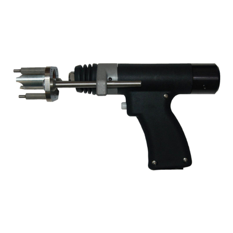
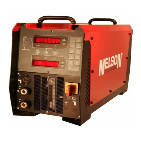
Nelson ALPHA 850 User manual

Operating manual
Studweldingunit
ALPHA
850
for
drawn arc and short-term drawn arc processes
Edition:
2021-07
Revision:
Rev. A / 07.2021 / EN
EN
Document number

ALPHA 850
Operating
manual
Model / Device:
Stud welding unit
Original-
Manufacturer
TUCKER GmbH
A Division of STANLEY Engineered Fastening
Max-Eyth-Straße 1
D-35394 Gießen, Germany
Tel.: +49 641 405 0
Fax: +49 641 405-383
E-mail: sef.europe@sbdinc.com
Internet:
www.tucker.eu
www.stanleyengineeredfastening.com/brands/tucker
Imprint
Responsible for the content from STANLEY Engineered Fastening in
this medium according to
Section 5 of the German Teleservices Act:
is the manufacturer Tucker GmbH
Stanley, Tucker and other logos are registered trademarks belonging
to Stanley Black & Decker, Inc.
Restricted confidentiality
No part of this manual may be transmitted, reproduced and/or copied
by any electronic or mechanical means without obtaining prior written
permission from Tucker GmbH!
© Copyright Tucker GmbH 2021. All rights reserved!

Table of Contents
Stud welding unit operating manual Date: July 2021
ALPHA 850 07.2021 / EN Rev.: A
TABLE OF CONTENTS
Chapter
Page
1Introduction.............................................................................................1
1.1 General remarks............................................................................1
1.2 Device description ........................................................................2
1.3 Weld process.................................................................................3
1.4 Process...........................................................................................4
1.5 Weld elements ...............................................................................5
1.6 Ceramic rings ................................................................................5
1.7 Material combinations..................................................................6
1.8 Technical data ...............................................................................7
1.9 Declaration of Conformity..........................................................11
2Work safety ...........................................................................................12
2.1 Safety symbols............................................................................12
2.2 Safety instructions......................................................................13
2.3 Intended use ................................................................................17
2.4 Warranty and liability..................................................................18
2.5 Copyright......................................................................................18
3Delivery and transport .........................................................................19
3.1 Scope of delivery ........................................................................19
3.2 Packaging and dispatch.............................................................19
3.3 Incoming inspection...................................................................19
3.4 Interim storage ............................................................................19
3.5 Transport......................................................................................19

Table of Contents
Stud welding unit operating manual Date: July 2021
ALPHA 850 07.2021 / EN Rev.: A
3.6 Location of use............................................................................20
3.7 Device set-up...............................................................................20
4Connection and installation................................................................21
4.1 Power cable connection.............................................................22
4.2 Welding cable connection..........................................................24
4.3 Control cable connection...........................................................25
4.4 Earth cable connection ..............................................................26
4.5 Workpiece connection................................................................26
5Control and display elements.............................................................28
5.1 Operating elements.....................................................................28
5.2 Display elements.........................................................................30
6Equipment fuses...................................................................................31
6.1 Fuse elements .............................................................................31
7Start-up and weld quality check.........................................................33
7.1 Notes about stud welding..........................................................33
7.2 Adjusting the weld parameters .................................................34
7.3 Commissioning conditions........................................................38
7.4 Functional test.............................................................................39
7.5 Checking weld quality ................................................................43
7.5.1 Visual inspection “drawn arc process” .......................................................44
7.5.2 Visual inspection “short cycle drawn arc process” .....................................45
8Maintenance..........................................................................................46
8.1 Care and cleaning .......................................................................46
8.2 Maintenance intervals.................................................................47
9Repairs...................................................................................................48

Table of Contents
Stud welding unit operating manual Date: July 2021
ALPHA 850 07.2021 / EN Rev.: A
9.1 Notes on repair............................................................................48
9.2 Troubleshooting..........................................................................49
10 Appendix................................................................................................55
10.1 Disposal of welding devices......................................................55
10.2 Abbreviations ..............................................................................58
10.3 Bibliography ................................................................................59

1 Introduction Page 1
Stud welding unit operating manual Date: July 2021
ALPHA 850 07.2021 / EN Rev.: A
1 Introduction
1.1 General remarks
This operating manual is about the ALPHA 850 welding device and is intended for
operating and service personnel.
The ALPHA 850 welding device can only be operated safely and reliably with
knowledge of the contents of this operating manual.
If anything is difficult or unclear, please contact Tucker customer service, who will be
glad to help you.
The illustrations, information and data in this operating manual were valid as of July
2021.
Tucker reserves the right to make technical changes that contribute to improvement of
the ALPHA 850 welding device.
Also follow our instructions for safely operating the system in chapter 9.2
“Troubleshooting” of this operating manual. This will greatly ease independent
solution of problems.
In addition, we recommend looking through DVS leaflet 0902 “Arc stud welding with
drawn arc” and DGUV information 209-010 “Arc welding”, as well as standards EN
ISO 14555 “Welding - Arc stud welding of metallic materials” and EN ISO 13918
“Welding - Studs and ceramic ferrules for arc stud welding”.

1 Introduction Page 2
Stud welding unit operating manual Date: July 2021
ALPHA 850 07.2021 / EN Rev.: A
1.2 Device description
The ALPHA 850 is a powerful welding device developed by Tucker for stud welding
according to the drawn arc process and short cycle drawn arc process.
Depending on the welding task, the ALPHA 850 can be configured with manually
loaded welding guns (standard operation) or automatic guns and sorting (automatic
mode).
The standard version of the ALPHA 850 has a 4-pin control cable socket.
When an automatic gun and a sorter of type NSA 606 M-NON AUTO “manual mode”
are connected, the studs are fed automatically. In this case, the welding device’s
control cable socket has 7 pins.
Information on safe, proper handling of the sorters and pistols can be found in the
specific device’s operating manual.
The ALPHA 850 works based on a fully controlled thyristor copper bar and delivers
constant welding currents up to 850 A. The AC grid power supply is transformed
through a transformer and then rectified.
The entire weld cycle is coordinated by the ALPHA 850’s control unit and can be
monitored with the LED display elements.
The welding current needed for stud welding and the weld times must be set on the
relevant potentiometers.
To keep the ALPHA 850’s temperature level as low as possible, the welding device
had a permanently controlled fan.
The stud welding process is selected according to the welding task and is set on the
welding device’s operating mode selector switch.
According to the short cycle process, SC studs with a weld diameter of 3 to 9 mm can
easily be welded without a weld pool guard.
The drawn arc process allows welding of ordinary commercial studs with a weld
diameter of 3 to 12 mm. To weld according to the drawn arc process, a weld pool
guard is necessary.
For protecting the weld pool, it is preferable to use ceramic rings or perform welding
under shielding gas (optional).

1 Introduction Page 3
Stud welding unit operating manual Date: July 2021
ALPHA 850 07.2021 / EN Rev.: A
1.3 Weld process
The ALPHA 850 welding device can be used to weld ordinary commercial studs
both in the short cycle drawn arc process (BH 10) as well as under the drawn arc
process (abbreviated BH 100).
The drawn arc process is for full-surface welding of studs of specific geometric
dimensions on metal workpieces that have a wall thickness of at least 1/4 of the
stud diameter.
To ensure de-oxidation of the melt bath and to improve ignition of the arc, the front
surfaces of the studs to be welded generally have a special aluminium preparation
adapted to the stud diameter.
To protect the weld pool from atmospheric influences and to centre the arc, it is
preferred that ceramic rings (CF) be used. This also prevents the melt from cooling
too fast.
For overhead welding or a horizontal welding position the ceramic ring (CF) forces a
constantly uniform shape of the weld bead and protects the user from weld
splatters.
In exceptional cases, such as when welding in tub position or reduction of the
aluminium preparation, weld pool guard can also be ensured by introducing
shielding gas (SG).
The shielding gas introduced drives the atmosphere out of the welding zone. If
welding is to be done with shielding gas, it is preferable to use studs with a conically
tapered welding tip.
The short cycle drawn arc process is a version of the drawn arc process that places
no special requirements on the stud tip design during extremely short weld times.
Other than the short weld times, the process is identical to arc welding with a drawn
arc.
With the short cycle drawn arc process. studs can even be welded to dirty, oily and
oiled workpiece surfaces, whose minimum sheet thickness must not be less than
0.6 mm.
Due to the extremely short weld times, the studs can also be easily welded without
ceramic rings. To protect the weld pool, especially during aluminium welding use of
shielding gas (SG) is recommended.

1 Introduction Page 4
Stud welding unit operating manual Date: July 2021
ALPHA 850 07.2021 / EN Rev.: A
1.4 Process
When welding according to the drawn arc and short cycle drawn arc processes, a
welding gun loaded with appropriate studs must be placed to the workpiece surface
at a right angle, to the degree possible.
Pressing the gun to the workpiece slides the stud back with the weld axis around
the stud stick out.
When the weld command is given, the pilot current flows over the short circuit path
of the stud and workpiece. The welding gun’s coil lifts the stud against the force
workpiece’s pressure spring.
When the weld stud is lifted from the workpiece, first an auxiliary arc is drawn and
then the main arc is ignited.
During the lift movement, the arc melts the front surface of the stud and a surface of
approximately the same size on the workpiece, so that a pool of liquid melt occurs
on the surfaces to be welded.
When the set weld time is over, power is cut off to the gun coil, so that the stud is
accelerated back onto the workpiece.
Immersion of the stud into the weld pool extinguishes the main arc and the weld
current is shut off. Before the melt bath stiffens, the stud is pressed into the still
liquid melt.
Immediately after, the welding gun is pulled from the cooled stud and can be
reloaded.
Process diagram:
1. Placing the 2. Pulling the 3. Igniting the 4. Immersing the 5. End of
weld stud auxiliary arc main arc weld stud weld
The weld time in the short cycle drawn arc process is about 10 ms –
100 ms.
The weld time in the drawn arc process is about 100 ms – 1000 ms.

1 Introduction Page 5
Stud welding unit operating manual Date: July 2021
ALPHA 850 07.2021 / EN Rev.: A
1.5 Weld elements
With the short cycle drawn arc process, threaded studs (SC-B; SC-Z), internally
threaded sockets (SC-I) and stud bolts (SC-S) of different dimensions and materials
can be welded.
According to the drawn arc process, threaded studs, head studs and cylinder pins
according to EN ISO 13918 can be welded.
The following conditions must be observed.
•At the work site, the welding gun is directed at the stud to be welded.
•The stud type is noted on the gun’s type plate.
•The studs to be welded are listed in chapter 1.8.
1.6 Ceramic rings
Ceramic rings (CF) are used to centre the arc and for shaping the weld bead
uniformly. At the same time, undesired atmospheric influences are shielded.
For welds on oblique or vertical walls and for overhead welds, the ceramic ring
prevents the melt bath from running and also protects the user from weld splatters.
The following conditions must be observed.
•A matching ceramic ring (CF) is necessary for every stud diameter.
•For different ceramic rings, corresponding ceramic ring holders are needed.

1 Introduction Page 6
Stud welding unit operating manual Date: July 2021
ALPHA 850 07.2021 / EN Rev.: A
1.7 Material combinations
The material combinations listed in the table below have already been tested. The
weld angle for the material combinations is defined as follows:
a = suitable for any application, such as force transfer,
b = suitable with limitations for force transfer,
c = suitable with limitations only for heat transfer,
–= cannot be welded.
Explanation of superscript numbers:
1) Up to 10 mm diameter and shielding gas in tub position (PA),
2) Only during short cycle stud welding with drawn arc,
3) Maximum yield strength ReH ≤ 460 N/mm2.
Material
combination
Base material
EN ISO 15614-1
*)
Groups 1 and 2 3) EN ISO 15614-1
*)
Groups 3 and 4 EN ISO 15614-1
*)
Group 9 EN ISO 15614-2
*)
Groups 21 and 22.1
Stud
S 235
4.8 (weld suitable)
16 Mo 3 a b b 2) –
X 10 CrAl 18
X 10 CrAl 24
X 10 CrNiSi 25-4 c c c –
1.4301, 1.4303
1.4401, 1.4451
1.4571 b (a) 1) b a –
EN AW-AlMg 3
EN AW AlMg 5 –––b
Group 1: Steels with minimum yield stress of ReH ≤ 360 N/mm2
Group 2: Standardized or thermodynamically treated fine-grain structural steels
with a minimum yield stress of Re> 500 N/mm2
Group 3: Annealed fine-grain structural steels with a minimum yield stress of
Re> 500 N/mm2
Group 4: Steels with Cr max. 0.75%, Mo max. 0.6%, V max. 0.3%
Group 9: Austenitic stainless steels
Group 21: Pure aluminium with max. 1.5% impurities
Group 22.1: Non-curable AlMg alloys with ≤3.5% Mg content
For material combinations that are not listed in the table, a Tucker expert must be
consulted.
*) EN ISO 15614-1, 2: Specification and qualification of welding procedures for metallic materials – Welding
procedure test

1 Introduction Page 7
Stud welding unit operating manual Date: July 2021
ALPHA 850 07.2021 / EN Rev.: A
1.8 Technical data
Device designation/type: ALPHA 850 welding device
Version: Europe standard
Input voltage: 3 ~ 400 V (± 10%); others on request
Grid frequency: 50/60 Hz
Power fuse: per phase 35 A (at 400 V)
Connected load: 68 kVA
Output power: max. 36 kW
No-load voltage: 96 V
Duty cycle: 3%
Welding current range: 100 A – 850 A
Welding time range: Short cycle: 10 ms – 100 ms
Drawn arc: 100 ms – 1000 ms
Fuse elements:
Supply to PCB control: F1: 1 A/250 V (slow)
Supply 18 VAC: F2: 4 A/250 V (slow)
Supply to coil circuit: F3: 4 A/50 V (slow)
Fan: F4: 3.15 mA/250 V (slow)
Protection type: IP 23
Protection class: I
Storage temperature: -25°C to +55°C
Operating temperature: 0°C to +40°C
Cooling type: Fan (AF)
Relative humidity: 0% to 50% at 40°C
0% to 90% at 20°C
Dimensions (L x W x H): 555 mm × 335 mm × 415 mm
Weight: 64 kg
Power plug: CEE; (3L+PE)
Power connection cable: H07RN-F
Length: 3 m
Cable diameter: 4 × 6.0 mm2
Minimum bending radius: 90mm

1 Introduction Page 8
Stud welding unit operating manual Date: July 2021
ALPHA 850 07.2021 / EN Rev.: A
Accessories (options):
•Weld guns for manual stud loading:
1 Welding gun: Type NS 40 SL
complete with accessories: see operating manual NS 40 SL
Shielding gas device: Order No. 67-03-04
1 Welding gun: Type NS 40 (B-1, B-2, B-3, B-4)
complete with accessories: see operating manual NS 40 B
Shielding gas device: Order No. 67-03-04
•Weld guns for automatic stud loading:
1 Welding gun: Type PFL 901
complete with accessories: see operating manual PFL 901
Shielding gas device: on request
•Sorter for automatic stud feeder:
1 Sorter (stud-specific): Type NSA 606 M-NON AUTO “manual
mode”
complete with accessories: see operating manual NSA 606 B
1 Power cable for sorter (220 V): Order No. 49-06-25
•Shielding gas-retrofit kit:
1 Retrofit kit (complete): Order No. 66-01-37
10 m shielding gas hose
system (ALPHA 850 gun): Order No. 67-07-50
•Catalogue:
“Fastening elements” catalogue: Order No. LFH 000
“Gun accessories” catalogue: Order No. LFZ 000

1 Introduction Page 9
Stud welding unit operating manual Date: July 2021
ALPHA 850 07.2021 / EN Rev.: A
Accessories (options):
•Connecting cable (standard):
ALPHA 850 - workpiece:
1 Earthing cable H01N2-D (with 2 earthing clips):
Cable diameter: 35 mm2
Minimum bending radius: 130mm
Length 5.0 m: Order No. 68-01-92
(others on request)
ALPHA 850 - sorter:
1 Cable set complete with welding cable and control cable:
Welding cable
Cable diameter: 50 mm2
Length 5.0 m: Order No. 68-03-63
(others on request)
Control cable, 7-pin:
Cable diameter: 8 × 0.5 mm2
Length 5.0 m: Order No. 68-04-82
(others on request)
•Connecting cable (extension):
ALPHA 850 - Gun NS 40:
1 Cable set complete with welding cable and control cable:
Welding cable diameter: 50 mm2
Control cable diameter: 4 × 1.5 mm2
Length 7.5 m: Order No. 67-01-16
Length 10.0 m: Order No. 67-03-29

1 Introduction Page 10
Stud welding unit operating manual Date: July 2021
ALPHA 850 07.2021 / EN Rev.: A
•Stud (types and dimensions):
SC stud for short cycle drawn arc process:
SC stud (type)
Shaft Ø / weld Ø
Threaded stud (SC - B) M3 - M8 / 4 mm - 9 mm
Stud bolt (SC - S) 3 mm - 9 mm
Internally threaded socket (SC
- I)
M3 - M5 / 7 mm - 9 mm
Sawtooth stud (SC - Z) M3 - M8 / 4 mm - 9 mm
DA stud for drawn arc process:
DA stud (type)
Shaft Ø / weld Ø
Threaded stud (MP, MPF) M6 - M12 / 5.3 mm - 10.8 mm
Threaded stud (M, MD) M8 - M12 / 6 mm - 12 mm
Threaded stud (MR) M6 - M12 / 4.7 mm - 9.5 mm
Stud bolt (SC - S) 3 mm - 12 mm
Internally threaded socket (MI) M4 - M8 / 10 mm - 12 mm
Head bolt (KB) ≤ 10 mm

1 Introduction Page 11
Stud welding unit operating manual Date: July 2021
ALPHA 850 07.2021 / EN Rev.: A
1.9 Declaration of Conformity
EU Declaration of Conformity in accordance with Machinery Directive
2006/42/EU Appendix II 1A
Document name:
Alpha 850_00_EN
Manufacturer:
Authorized to compile technical
documentation:
STANLEY Engineered Fastening
Matthias Appel
TUCKER GmbH
TUCKER GmbH
Max-Eyth-Strasse 1
Max-Eyth-Strasse 1
35394 Giessen
35394 Gießen
Germany
Germany
Product name:
Control and power unit for stud arc welding
Models:
Alpha 850
Serial Number:
Year of construction:
The manufacturer hereby declares that the products stipulated above comply with all
relevant provisions and requirements of the following applicable directives:
2006/42/EU – Machine directive
2014/30/EU ‒ EMC Directive
The conformity assessment was conducted for machines not subject to Appendix IV with
internal production controls for manufacturing machines according to Appendix VIII.
References of the directives as published in the Official Journal of the European Union.
The following harmonized standards were used:
DIN EN IEC 60974-1:2018-12
Arc welding equipment - Part 1: Welding power sources
DIN EN IEC 60974-12:2012-03
Arc welding equipment - Part 12: Coupling devices for
welding cables
DIN EN 60204-1:2019-06
Safety of machinery - Electrical equipment of machines -
Part 1: General requirements
DIN EN 60529:2014-09
Degrees of protection provided by enclosures
Notified body:
EMC Test NRW GmbH
Emil-Figge-Straße 76, 44227 Dortmund
EU ID number:
1946
EU type examination certificate:
010/21-d
Represented by the chief executive officer:
Thomas Ehrhardt
Location, date:
Giessen, 2021-08-25
Legally binding signature:
This declaration certifies conformity with the above-mentioned guidelines

2 Work safety Page 12
Stud welding unit operating manual Date: July 2021
ALPHA 850 07.2021 / EN Rev.: A
2 Work safety
2.1 Safety symbols
Safety instructions and warnings are for your personal safety and for product safety.
In this operating manual, they are highlighted by the following safety symbols.
The safety symbol used has the following meaning:
The caution sign calls attention to potentially hazardous situations. It
is always used in connection with one of the additional terms defined
below.
The additional terms have the following meaning:
Danger: This means that death, severe bodily injury or severe property
damage will occur if the appropriate precautionary measures are not
taken.
Warning: This means that death, severe bodily injury or severe property
damage may occur if the appropriate precautionary measures are not
taken.
Caution: This means that minor bodily injury or property damage may occur if
the appropriate precautionary measures are not taken.
This sign indicates important information about proper handling of the
product or special instructions that should receive special attention.
Warning:
•Everyone who works on the ALPHA 850 is obligated, before starting
work, to read and follow the safety instructions in this operating
manual!
•The system owner is obligated to allow only people familiar with the
work safety and accident prevention regulations to work on the
ALPHA 850.

2 Work safety Page 13
Stud welding unit operating manual Date: July 2021
ALPHA 850 07.2021 / EN Rev.: A
2.2 Safety instructions
A prerequisite for safe handling and trouble-free operation of the ALPHA 850 welding
device is knowledge of the following safety instructions.
Informal safety instructions:
•The operating manual must always be stored at the place where the ALPHA 850 is
used.
•The safety symbols and type plate must be kept legible.
Training of personnel:
•The stud welding system’s operating personnel must:
- be trained in handling welding technology equipment,
- have had stud welding qualification training,
- know the content of this operating manual.
•Set-up and electrical personnel must:
- have had training enabling them to make repairs,
- have authorization to start up electrical circuits and devices according to the
safety standards.
•Personnel in training are allowed to:
- work on the welding system only under the supervision of experienced technical
personnel.
Personal safety equipment:
•It is mandatory to wear the following safety equipment:
flame-resistant safety clothing covering the entire body,
welder’s goggles with protection filter (per EN 169),
Safety gloves,
safety helmet (for overhead welding),
Ear protection (plugs, headset) is recommended.
•During welding, touchable parts of the welding gun, such as studs, stud holder and
all electrically connected parts carry current.
Therefore, do not wear any electrically conductive jewellery (ring, watch or chain)!

2 Work safety Page 14
Stud welding unit operating manual Date: July 2021
ALPHA 850 07.2021 / EN Rev.: A
Safety measures at the workplace:
The workplace must be so arranged that people nearby are adequately protected
against damaging effects of optical radiation.
Spacial boundaries and shields must be set up to prevent reflections and penetration
by radiation to the greatest extent possible.
Combustible and flammable materials must be removed from the welding zone. It
must be ensured that a fire extinguisher is available at the workplace.
Ensure adequate ventilation and lighting at the workplace.
Weld only in rooms and areas where no hazards from fire, explosion,
smoke, fumes or moisture can occur.
When in doubt, an authorized welding supervisor or fire protection officer must be
consulted.
Depending on the process, stud welding can produce strong electromagnetic fields.
These can:
- be life-threatening for people with heart pacemakers,
- disturb or damage electrical or electronic devices,
- irrecoverably erase magnetic storage media,
- magnetize and damage watches.
The weld current cables also produce strong electromagnetic fields.
Make sure that the welding and earthing cables are as free of loops as possible and
are laid at an adequate distance from unrelated electrical devices.
This especially applies when welding at construction sites and on special
equipment.
When in doubt, check with the device manufacturer for the construction site or
special equipment.
The system owner is obligated to take suitable corrective measures.
Warning:
•The ALPHA 850 welding device is suitable according to standard EN
55011 for use in an industrial environment (limit class A).
•It is explicitly pointed out that devices in limit class A can cause radio
interference in residential and business areas.

2 Work safety Page 15
Stud welding unit operating manual Date: July 2021
ALPHA 850 07.2021 / EN Rev.: A
Safety measures before starting work:
•Before starting work (shift change), check:
- all safety equipment for correct attachment,
- all system components for externally visible damage,
- all connection cables for loose contacts and scorch marks.
Warning:
•During the welding process, touchable parts of the welding gun, such
as studs, stud holder and all electrically connected parts carry current.
These components must not be touched during the welding process!
•Do not wear any electrically conductive jewellery, such as rings,
watches or chains!
•It is explicitly pointed out that devices in limit class A can cause radio
interference in residential and business areas.
Safety measures during normal operation:
•Use welding systems only in technically perfect condition.
•Any unsafe way of working must be avoided.
Safety measures after finishing work:
•Turn off the welding device and pull the power plug.
•Secure and mark the welding device against unauthorized use.
•Adhere to the specified maintenance intervals.
Safety measures during malfunction mode:
•Turn off the welding device and pull the power plug.
•Secure and mark the welding device against being turned back on.
•After repair, the system’s operational capability must be ensured.
Warning:
•Only authorized electro-technical personnel are allowed to open the
welding device or work inside its housing.
•Before the welding device is closed, the earth conductor must be
connected to the device housing.
Table of contents
Other Nelson Welding System manuals

Nelson
Nelson N1500i Operation manual

Nelson
Nelson NCD+ 1000T User manual

Nelson
Nelson NCD+ Auto-Gap Gun Instructions for use

Nelson
Nelson N1500i User manual

Nelson
Nelson ArcCharger N550C DOMESTIC User manual

Nelson
Nelson NCD+ Instructions for use

Nelson
Nelson N1500i User manual

Nelson
Nelson NS20A Instructions for use

Nelson
Nelson NCD+ 3200 User manual

Nelson
Nelson Nelweld 4000 Operation manual
Popular Welding System manuals by other brands

Miller
Miller Continuum 350 owner's manual

Magmaweld
Magmaweld RS 350 M - MW user manual

voestalpine
voestalpine Bohler URANOS 2000 SMC instruction manual

SAF
SAF SAFEX M 253 Safety instruction for use and maintenance

Miller Electric
Miller Electric WD-5 owner's manual

ESAB
ESAB CoolMidi 1800 instruction manual