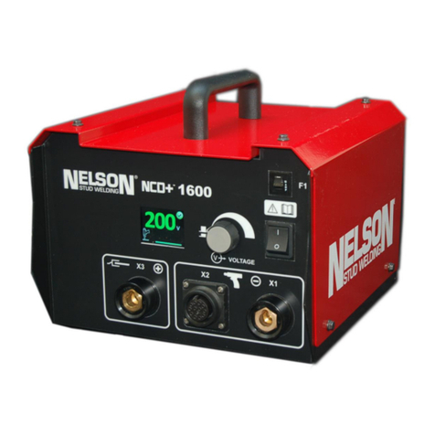
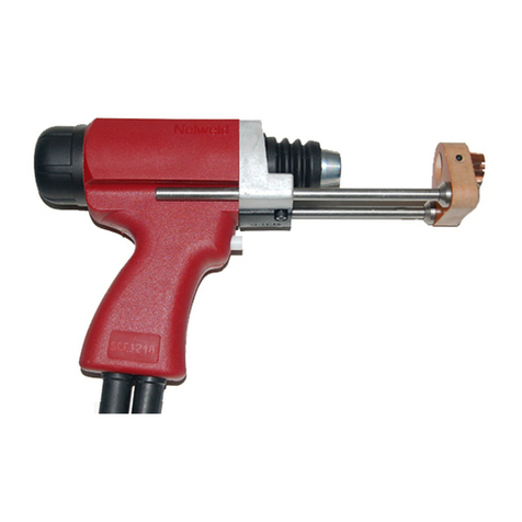
Nelson NCD+ Auto-Gap Gun Instructions for use

© 2016 Nelson Stud Welding, Inc. Page 1
All Rights Reserved. February 2016 Part No. 729-110-042 v1.03
NCD+ Auto-Gap Gun
Instruction & Maintenance Manual
(729-110-042)
These instructions are intended for experienced operators.
If you are not fully familiar with the principles of operation and safe practices for arc
welding equipment, we urge you to read AWS SP –“Safe Practices” available from
the American Welding Society.
Do not permit untrained persons to install, operate or maintain the equipment. Do not attempt to install or
operate the equipment until you have read and fully understand these instructions.
If you do not fully understand these instructions, contact your supplier for further information. Be sure to read the Safety
section before utilizing this equipment.

© 2016 Nelson Stud Welding, Inc. Page 2
All Rights Reserved. February 2016 Part No. 729-110-042 v1.03
NCD+ Limited Warranty
Nelson’s only warranty is that goods being sold will be free from defects in workmanship
and material. This warranty is expressly in lieu of other warranties, expressed or implied
and whether statutory or otherwise, including any implied warranty of merchantability or
fitness for a particular purpose.
Nelson’s liability for breach of warranty shall arise only upon return of the defective
goods at Buyer’s expense after notice to Nelson of the claimed breach, and shall be
limited to furnishing a like quantity of such goods free from such defects or, at Nelson’s
option, to refunding the purchase price (less reasonable depreciation based on actual
use); provided, however, that Nelson will not accept receipt of equipment returned
unless buyer has previously afforded Nelson’s personnel a reasonable opportunity to
inspect and repair said equipment at buyer’s facility or such other location as is mutually
agreeable. Notice to Nelson must be given within 30 days of such defect or failure and
within 90 days from the date the equipment was delivered, whichever comes first. No
compensation or reimbursement for transportation costs of any kind will be allowed.
Please note that this warranty does not extend beyond the original registered purchaser,
and does not warrant equipment that has been modified by any party other than Nelson,
or equipment that has been improperly installed, improperly operated, or misused based
upon industry standards, or equipment which has not had reasonable and necessary
maintenance, or equipment which has been used for operation outside of specifications
for the equipment. Nelson shall never be liable for consequential damages.
Nelson reserves the right to make engineering and/or part changes, at any time without
notice, as a result of our commitment to continuous improvement.

© 2016 Nelson Stud Welding, Inc. Page 3
All Rights Reserved. February 2016 Part No. 729-110-042 v1.03
WARNING
The following Safety section is for your
protection. It summarizes
precautionary information from the
references listed in the Additional
Safety Information section. Before performing any installation or operating
procedures, be sure to read and follow the safety precautions listed below as
well as all other manuals, material safety data sheets, labels, etc. Failure to
observe these precautions can result in injury or death.
ELECTRICAL SHOCK
Contact with live electrical parts and ground can cause
severe injury or death. DO NOT use welding current in
damp areas, if movement is confined, or if there is
danger of falling. Therefore:
1. Be sure the power source frame (chassis) is connected to the ground
system of the input power.
2. Connect the work piece to a good electrical ground.
3. Connect the work cable to the work piece. A poor or missing connection
can expose you or others to a fatal shock.
4. Use well-maintained equipment. Replace worn or damaged cables.
5. Keep everything dry, including clothing, work area, cables, torch/electrode
holder and power source.
6. Make sure that all parts of your body are insulated from work and from the
ground.
7. Do not stand directly on metal or the earth while working in tight quarters
or a damp area; stand on dry boards or an insulating platform and wear
rubber soled shoes.
8. Put on dry, hole-free gloves before turning on the power.
9. Refer to ANSI/ASC Standard Z49.1 for specific grounding
recommendations. Do not mistake the work lead for a ground cable.
PROTECT YOURSELF AND OTHERS
Some welding, cutting, and gouging processes are
noisy and require ear protection. The arc, like the sun,
emits ultraviolet (UV) rays and other radiation which can
harm the skin and eyes. Hot metal can cause burns.
Training in the proper use of the processes and
equipment is essential to prevent accidents. Therefore:
1. Always wear safety glasses with side shields in any work area, even if
welding helmets, face shields and goggles are also required.
2. Use a face shield fitted with filter shade #3 per ANSI Z87.1. Cover sparks
and rays of the arc when operating or observing operations. Warn
bystanders not to watch the arc and not to expose themselves to the rays
of the electric-arc or hot metal.
3. Wear flameproof gauntlet type gloves, heavy long-sleeve shirt, cuffless
trousers, high topped shoes, and a welding helmet or cap for hair
protection, to protect against arc rays and hot sparks or hot metal. A
flameproof apron may also be desirable as protection against radiated
heat and sparks.
4. Hot sparks or metal can lodge in rolled up sleeves, trousers cuffs or
pockets. Sleeves and collars should be kept buttoned and open pockets
eliminated from the front of clothing.
5. Protect other personnel from arc rays and hot sparks with suitable
nonflammable partitions or curtains.
6. Use goggles over safety glasses when chipping slag or grinding. Chipped
slag may be hot and can fly far. Bystanders should also wear goggles
over safety glasses.
ELECTRICAL AND MAGNETIC FIELDS
Electric and magnetic fields may be dangerous.
Electric current flowing through any conductor causes
localized Electric and Magnetic Fields (EMF). Welding
and cutting current creates EMF around welding
cables and welding machines. Therefore:
1. Operators having pacemakers should consult their physician before
welding. EMF may interfere with some pacemakers.
2. Exposure to EMF may have other health effects which are unknown.
3. Operators should use the following procedures to minimize exposure to
EMF:
4. Route the electrode and work cables together. Secure them with tape
when possible.
5. Never coil the torch or work cable around your body.
6. Do not place your body between the torch and work cables. Route cables
on the same side of your body.
7. Connect the work cable to the work piece as close as possible to the area
being welded.
8. Keep welding power source and cables as far away from your body as
possible.
FIRES AND EXPLOSIONS
Heat from flames and arcs can start fires. Hot slag or
sparks can also cause fires and explosions. Therefore:
1. Remove all combustible materials well away from the work area or cover
the materials with a protective nonflammable covering. Combustible
materials include wood, cloth, sawdust, liquid and gas fuels, solvents,
paints and coatings, paper, etc.
2. Hot sparks or hot metal can fall through cracks or crevices in floors or wall
openings and cause a hidden smoldering fire or fires on the floor below.
Make certain that such openings are protected from hot sparks and metal.
3. Do not weld, cut, or perform other hot work until the work piece has been
completely cleaned so that there are no substances on the work piece
which might produce flammable or toxic vapors. Do not do hot work on
closed containers. They may explode.
4. Have appropriate fire extinguishing equipment handy for instant use, such
as a garden hose, water pail, sand bucket or portable fire extinguisher. Be
sure you are trained for proper use.
5. Do not use equipment beyond its ratings. For example, overloaded
welding cable can overheat and create a fire hazard.
6. After completing operations, inspect the work area to make certain there
are no hot sparks or hot metal which could cause a later fire. Use fire
watchers when necessary.
7. For additional information, refer to NFPA Standard 51B, “Fire Prevention
in Use of Cutting and Welding Processes,” available from the National Fire
Protection Association, Batterymarch Park, Quincy, MA 02269
FUMES AND GASES
Fumes and gases can cause discomfort or harm,
particularly in confined spaces. Do not breathe fumes
and gases. Shielding gases can cause asphyxiation.
Therefore:
1. Always provide adequate ventilation in the work area by natural or
mechanical means. Do not weld, cut, or gouge on materials such as
galvanized steel, stainless steel, copper, zinc, lead, beryllium, or cadmium
unless positive mechanical ventilation is provided. Do not breathe fumes
from these materials.
2. Do not operate near degreasing and spraying operations. The heat or arc
rays can react with chlorinated hydrocarbon vapors to form phosgene, a
highly toxic gas, and other irritant gasses.
3. If you develop momentary eye, nose, or throat irritation while operating,
this is an indication that ventilation is not adequate. Stop work and take
necessary steps to improve ventilation in the work areas. Do not continue
to operate if physical discomfort persists.
4. Refer to ANSI/ASC Standard Z49.1 (see listing on next page) for specific
ventilation recommendations.
© 2016 Nelson Stud Welding, Inc. Page 4
All Rights Reserved. February 2016 Part No. 729-110-042 v1.03
ELECTRICALLY POWERED EQUIPMENT
Faulty or improperly electrified equipment can cause
injury or death. Therefore:
EYE PROTECTION
Flying metal can injure eyes. Welding, chipping, wire
brushing and grinding can cause sparks and flying metal.
As welds cool, they can throw off slag. Therefore:
1. Always have qualified personnel perform the installation, troubleshooting,
and maintenance work. Do not perform any electrical work unless you are
qualified to perform such work.
2. Before performing any work inside a power source, disconnect the power
source from the incoming electrical power using the disconnect switch at the
fuse box before working on the equipment.
3. Install equipment in accordance with the U.S. National Electrical Code, all
local codes and the manufacture’s recommendations.
4. Ground the equipment in accordance with the U.S. National Electrical Code
and the manufacturer’s recommendations.
1. Wear approved safety glasses with side shields even under your welding
helmet.
2. Warn others nearby about flying metal hazard.
EQUIPMENT MAINTENANCE
Faulty or improperly maintained equipment can cause
injury or death. Therefore:
CYLINDER HANDLING
Cylinders, if mishandled, can rupture and violently
release gas. Sudden rupture of cylinder, valve, or relief
device can injure or kill. Therefore:
1. Always have qualified personnel perform the installation, troubleshooting,
and maintenance work. Do not perform any electrical work unless you are
qualified to perform such work.
2. Before performing any maintenance work inside a power source, disconnect
the power source from the incoming electrical power.
3. Maintain cables, grounding wire, connections, power cord, and power supply
in safe working order. Do not operate any equipment in faulty condition.
4. Do not abuse any equipment or accessories. Keep equipment away from:
heat sources such as furnaces
wet conditions such as water puddles and inclement weather
oil or grease
corrosive atmospheres
5. Keep all safety devices and cabinet covers in position and in good repair.
6. Use equipment only for its intended purpose. Do not modify it in any
manner.
1. Use the proper gas for the process and use the proper pressure reducing
regulator designed to operate from the compressed gas cylinder. Do not use
adaptors. Maintain hoses and fittings in good condition.
2. Always secure cylinders in an upright position by chain or strap to suitable
hand trucks, undercarriages, benches, walls, post, or racks. Never secure
cylinders to work tables or fixtures where they may become part of an
electrical circuit.
3. When not in use, keep cylinder valves closed. Have valve protection cap in
place if regulator is not connected. Secure and move cylinders by using
suitable hand trucks. Avoid rough handling of cylinders.
4. Locate cylinders away from heat, sparks, and flames. Never strike an arc on
a cylinder.
5. For additional information, refer to CGA Standard P-1, “Precautions for Safe
Handling of Compressed Gases in Cylinders”, which is available from
Compressed Gas Association, 1235 Jefferson Davis Highway, Arlington, VA
22202.
ADDITIONAL SAFETY INFORMATION
For more information on safe practices for electric arc
welding, refer to the following publications.
HEARING PROTECTION
Prolonged Noise from Capacitor Discharge welding
applications can damage hearing if levels exceed limits
specified by OSHA. Therefore:
1. ANSI/ASC Z49.1 Safety in Welding and Cutting
2. AWS C5.1 Recommended Practices for Plasma Arc Welding
3. AWS C5.6 Recommended Practices for Gas Metal Arc Welding
4. AWS SP Safe Practices (Reprint) Welding Handbook
5. ANSI/AWS F4.1 Recommended Safe Practices for Welding and Cutting of
Containers That Have Held
Hazardous Substances.
1. Use Approved ear plugs or ear muffs if noise level is high.
2. Warn others nearby about noise hazard.
3. For additional information, refer to OSHA Safety Standards 3074.
MOVING PARTS CAN CAUSE INJURY
Electric fan can start at any time without warning and
cause severe injury, therefore:
1. Always disconnect electrical power prior to service to prevent the fan from
starting unexpectedly.
2. Keep all doors, panels, covers, and guards closed and securely in place.
3. Have only qualified people remove guards or covers for maintenance and
troubleshooting as necessary.
4. Keep hands, hair, loose clothing, and tools away from moving parts.
5. Reinstall panels or guards and close doors when servicing is finished and
before reenergizing welder.

© 2016 Nelson Stud Welding, Inc. Page 5
All Rights Reserved. February 2016 Part No. 729-110-042 v1.03
Contents
1Overview..............................................................................................................................................................7
1.1 Nelson NCD+ Welding Modes....................................................................................................................8
1.1.1 Contact Mode Capacitor Discharge Welding......................................................................................8
1.1.2 Gap Mode Capacitor Discharge Welding...........................................................................................8
1.2 NCD+ Guns ................................................................................................................................................9
1.2.1 Operation of the Auto-Gap Gun (Gap Mode) .....................................................................................9
1.2.2 Operation of the Auto-Gap Gun (Contact Mode)................................................................................9
2Features ........................................................................................................................................................... 10
3Gun Set-Up....................................................................................................................................................... 11
3.1 Chuck Assembly Instructions ...................................................................................................................11
3.1.1 Chuck Assembly.............................................................................................................................. 11
3.1.2 Adjusting Chuck and Stop Assembly............................................................................................... 11
3.1.3 Adjusting Stud Stop Assembly ........................................................................................................ 11
3.2 Setting Up Foot and Leg Assembly..........................................................................................................12
3.3 Setting Spring Pressure (Auto-Gap Mode)...............................................................................................13
3.3.1 Setting Travel/Lift and Spring Pressure in Gap Mode..................................................................... 13
3.3.2 Setting Spring Pressure in Contact Mode ....................................................................................... 14
3.3.3 Changing Your Tool To Weld with Contact ..................................................................................... 15
4Weld Setup....................................................................................................................................................... 16
4.1 Auto-Gap Gun...........................................................................................................................................16
4.2 Post Weld .................................................................................................................................................16
5Maintenance of Stud Welding System ............................................................................................................. 17
5.1 Stud Welding Gun.....................................................................................................................................17
5.2 Welding Cable / Control Cable.................................................................................................................17
5.3 Power Control Unit....................................................................................................................................17
6Troubleshooting................................................................................................................................................ 18
6.1 Visual Weld Inspection and Weld Parameter Adjustments......................................................................18
6.2 Weld Quality Physical Inspection and Weld Parameter Adjustments......................................................18
6.2.1 Recommendations........................................................................................................................... 18
7Exploded Drawings & Parts List....................................................................................................................... 21
7.1 Parts List...................................................................................................................................................21
7.2 Exploded Drawing.....................................................................................................................................23
7.3 Electrical Functions of Guns.....................................................................................................................24
7.3.1 Coil Power Circuit ............................................................................................................................ 24

© 2016 Nelson Stud Welding, Inc. Page 6
All Rights Reserved. February 2016 Part No. 729-110-042 v1.03
7.3.2 Triggering Contact ........................................................................................................................... 24
7.4 Gun Coding...............................................................................................................................................24
7.4.1 Dismantling & Reassembling Gap & Contact Welding Guns .......................................................... 24
8Schematics....................................................................................................................................................... 25
8.1 NCD+ CTRL TO GUN, 12 PIN, Auto-Gap................................................................................................25
8.2 Specifications............................................................................................................................................26
8.3 Accessories ..............................................................................................................................................27
8.4 Table of Weld Parameters................................................................................................................................. 28
9Contact Information.......................................................................................................................................... 29

© 2016 Nelson Stud Welding, Inc. Page 7
All Rights Reserved. February 2016 Part No. 729-110-042 v1.03
1 Overview
The Nelson NCD+ stud welding guns are made to be used with Nelson NCD+ stud welding power units, which
utilize the capacitor discharge principal of stud welding. This system is designed to use fasteners, which are
manufactured with a small projection on the weld end and are welded by either the Contact or Gap method. Heat
for fusion is obtained from an electric arc, which is established by flashing away the small projection. The
discharge of the welding current or energy stored in the capacitors produces an arc that melts the end of the stud
and a portion of the base material. The stud is forced into the molten metal before the conclusion of the arc cycle.
Upon cooling, a uniform cross section bond is achieved. A special advantage of the capacitor discharge process
is the limited heat generated, and low penetration which allows the fasteners to be welded to thin and/or coated
parts opposite the weld side.
Selection of the “gap” or “contact” welding mode is application dependent. Gap welding usually provides superior
weld reliability with aluminum and other non-ferrous metals. Contact welding is generally used with carbon steel
and stainless steel especially when weld appearance is not a prime consideration. The contact welding setup is
easier to make and the contact mode is somewhat more tolerant to work piece flexing.
The welding guns in this series are a “contact gun” which is suitable only for contact welding and an “auto-gap
gun” which is suitable for both gap and contact welding.
NOTE: Depending upon the weld setup established for any particular stud size or material, the noise generated by the
flashing away of the stud tip may exceed the allowable level established by the Occupational Safety and Health
Administration (Section 50-204.10 of the Federal Register, Part II). For this reason, it is recommended that the stud
welding operator and anyone working within the immediate area of the stud welding operation use proper ear
protection.
SAFETY SYMBOLS
ATTENTION! BE
ALERT! Your safety
is involved.
Used to call attention to immediate hazards which, if not
avoided, will result in immediate, serious personal injury or
loss of life.
Used to call attention to potential hazards which could
result in personal injury or loss of life.
Used to call attention to hazards which could result in minor
personal injury.

© 2016 Nelson Stud Welding, Inc. Page 8
All Rights Reserved. February 2016 Part No. 729-110-042 v1.03
1.1 Nelson NCD+ Welding Modes
There are 2 modes of the CD welding process offered with the NCD+ line of equipment: Contact and Auto-Gap.
Each method has its own uses and set-up requirements. The method you select will be determined by the metals
to be joined, esthetics, strength and fixturing. Nelson Stud Welding can assist you in determining which method
and settings best suit your needs.
1.1.1 Contact Mode Capacitor Discharge Welding
1. Gun is loaded and properly positioned with the stud in contact with the work. Operator takes up the spring
pressure.
2. The trigger is closed the projection tip is flashed off leaving an arc space.
3. The remaining stored energy is discharged across the arc space (Stud and base material are heated).
4. The spring pressure plunges the stud into the work piece.
5. The weld solidifies and connection is complete.
Figure 1.1 Contact Mode
1.1.2 Gap Mode Capacitor Discharge Welding
1. Gun is loaded and properly positioned with the stud in contact with the work. Operator takes up the
spring pressure.
2. The trigger is closed and the coil lifts the stud momentarily.
3. The coil is de-energized. Spring pressure forces the stud to contact the work piece.
4. Upon contact the projection tip is flashed off leaving an arc space.
5. The remaining stored energy is discharged across the arc space (Stud and base material are heated).
6. The spring pressure plunges the stud into the work piece.
7. The weld solidifies and connection is complete.
Figure 1.2 Gap Mode

© 2016 Nelson Stud Welding, Inc. Page 9
All Rights Reserved. February 2016 Part No. 729-110-042 v1.03
1.2 NCD+ Guns
This manual covers the Auto-Gap weld gun. This gun can be used for Auto-Gap and Contact style welding
applications.
1.2.1 Operation of the Auto-Gap Gun (Gap Mode)
The NCD+ Auto-Gap gun is a capacitor discharge lift gun. There are two wires in the control cable that go to the
gun coil and two wires that go to the trigger. When the trigger is pulled, the stud rises off the workpiece. The gun
de-energizes and the main spring then pushes the stud back towards the workpiece. The arc begins once the
stud contacts the work.
1.2.2 Operation of the Auto-Gap Gun (Contact Mode)
The NCD+ Auto-Gap Gun can also be used as a capacitor discharge contact gun. The coil does not lift the stud in
this application. When the trigger is pulled, the capacitors discharge as the stud is held firmly against the
workpiece. The tip is flashed off, that establishes an arc and allows the stud to plunge.

© 2016 Nelson Stud Welding, Inc. Page 10
All Rights Reserved. February 2016 Part No. 729-110-042 v1.03
2 Features
1
CHUCK NUT
2
TRIGGER
3
CONTROL CABLE
4
WELD CABLE
5
GUN BODY (2 HALVES)
6
FOOT ASSEMBLY
7
BELLOWS
8
SPRING ADJUSTMENT COLLAR
9
MAIN SPRING
10
REAR CAP AND TRAVEL ADJ SCREW

© 2016 Nelson Stud Welding, Inc. Page 11
All Rights Reserved. February 2016 Part No. 729-110-042 v1.03
3 Gun Set-Up
3.1 Chuck Assembly Instructions
The unit should be switched off before inserting or changing a chuck.
3.1.1 Chuck Assembly
At the beginning of a welding series or in case of a necessary change to different stud dimensions, the chuck
must be set to the correct stud type.
The chucks (Figure 3.1 Chuck and Stop Assembly) are not included and should be ordered separately.
*See
Accessories”for correct sizes and part numbers.
Job Preparation
Tools Required: Screwdriver, open-end wrench (7mm, 8mm), and caliper gauge
1 Select chuck with the correct diameter for the stud to be welded.
2 Stop pin assembly for the proper stud length.
3.1.2 Adjusting Chuck and Stop Assembly
The unit should be switched off before inserting or changing a chuck.
To adjust the Chuck and Stop Assembly (Figure 3.1 Chuck and Stop Assembly):
The proper size chuck for the type of stud being welded must be used to ensure good electrical contact between
the stud and the stud chuck. If the stud fit seems too loose with the proper chuck, the chuck tines may be pressed
slightly together at the front end of the chuck.
3.1.3 Adjusting Stud Stop Assembly
1 Loosen the set screw.
2 Adjust the stud stop so that the stud being welded extends 4 mm beyond the chuck.
3 Tighten set screw.
NOTE: For long studs, use maximum chuck depth. The chuck is assembled as shown and inserted into the chuck
adaptor. The chuck must be in
firm contact with the stud stop
while tightening the chuck nut.
Figure 3.1 Chuck and Stop Assembly

© 2016 Nelson Stud Welding, Inc. Page 12
All Rights Reserved. February 2016 Part No. 729-110-042 v1.03
3.2 Setting Up Foot and Leg Assembly
The NCD+ guns come supplied with a foot and spark shield (Figure 3.2a Spark shield Foot & Leg Assembly). The
foot is installed on the end of the legs. Alignment of the foot is important. The chuck should be located in the
center of the spark shield. To install the foot, unscrew the leg screws and place them through the holes in the foot.
Reattach the leg screws to the legs. Maintain concentricity between the chuck and spark shield.
Figure 3.2a Spark shield Foot & Leg Assembly
Also included with the foot & leg assembly are three locating pins used to make the tripod setup. The spark shield
and the locating pins may be used together or independently during welding operations.
Figure 3.3b Tripod Foot & Leg Assembly
*See section 7 for part numbers

© 2016 Nelson Stud Welding, Inc. Page 13
All Rights Reserved. February 2016 Part No. 729-110-042 v1.03
3.3 Setting Spring Pressure (Auto-Gap Mode)
3.3.1 Setting Travel/Lift and Spring Pressure in Gap Mode
In the Auto-Gap Capacitor Discharge welding process, the distance the stud is lifted from the work-piece is called
the gap. The plunge rate is affected by the amount of travel and the spring pressure selected. To properly adjust
the lift and spring pressure, it is important to make the adjustments as follows.
Figure 3.4a Figure 3.3b
Required tools: NCD+ Weld gun, chuck and foot per application, flat bladed screwdriver
1 Ensure the included standard duty gap spring is installed.
2 Check Section 8.4 Table of Weld Parameters for the recommended spring pressure and lift.
3 With a flat bladed screwdriver or NCD+ Set-Up Tool #525-001-200, turn the travel adjustment screw on the
back of the weld gun counter clockwise until it stops.
4 Loosen leg screws.
5 Insert stud in chuck.
6 Adjust foot so that the stud-stick out matches the desired plunge.
7 Tighten leg screws to lock tripod foot or spark shield in place.
8 With a stud in the gun, compress the gun against a non-conductive block. Trigger the gun to see if the
chuck and stud will retract. It should not retract.
9 Back the travel adjustment screw out one mark at a time until the position is found where the gun just starts
to lift.
10 From this start point adjust the travel adjustment screw for the desired lift. Each line is equal to approx .005”
of lift. So for .100” of lift it would be necessary to turn 20 marks. See Fig. 3.3a
11 Turn the spring pressure adjustment knob to desired spring pressure. For the included standard duty gap
spring each mark equates to .25 lbs of spring force and the minimum is 4 lbs. See Fig. 3.3b

© 2016 Nelson Stud Welding, Inc. Page 14
All Rights Reserved. February 2016 Part No. 729-110-042 v1.03
3.3.2 Setting Spring Pressure in Contact Mode
Required tools: NCD+ Weld gun, chuck and foot per application, flat bladed screwdriver
1 Ensure Contact spring is installed per section 3.3.3
2 Check Section 8.4 Table of Weld Parameters for the recommended spring pressure.
3 With a flat bladed screwdriver or NCD+ Set-Up Tool #525-001-200, turn travel adjustment screw on the back
of the weld gun counter clockwise until it stops.
4 Loosen leg screws.
5 Insert stud in chuck.
6 Adjust foot so that the stud stick-out matches the desired plunge.
7 Tighten leg screws to lock tripod foot or spark shield in place.
8 With a stud in the gun, compress the gun against a non-conductive block. Trigger the gun to see if the
chuck and stud will retract. It should not retract.
9 Turn the spring pressure adjustment knob to desired spring pressure. For the contact spring each mark
equates to 1 lb of spring force and the minimum is 7 lbs.

© 2016 Nelson Stud Welding, Inc. Page 15
All Rights Reserved. February 2016 Part No. 729-110-042 v1.03
3.3.3 Changing Your Tool to Weld with Contact
Included with the Auto-Gap weld tool is a second spring. This is used for changing the weld tool to weld in
contact mode. In order to make this change, follow these steps.
1. Loosen set screws #5. (2 places)
2. Remove the foot and leg assembly and bellows.
3. Remove the chuck nut and chuck.
4. Unscrew part #41 and remove.
5. Loosen set screws #6 (2 Places)
6. Remove front cover, part 28, and plastic bearing, part 40.
7. Change part 13 Main spring.
8. Re-assemble in reverse order.
526-001-234 Pre-installed Gap spring 526-001-268 Contact Spring included with tool.

© 2016 Nelson Stud Welding, Inc. Page 16
All Rights Reserved. February 2016 Part No. 729-110-042 v1.03
4 Weld Setup
4.1 Auto-Gap Gun
1 Confirm the power unit is switched off.
2 Connect gun and ground cables to the appropriate terminals.
3 Set spring pressure and gap/lift using a stud per section 3.3.1.
4 Adjust voltage.
5 Replace the set up stud with a new one.
6 Begin production welding after sample welds have been validated for strength and appearance.
4.2 Post Weld
During welding, it is very important to draw the chuck (gun) straight off the stud after a weld has been made to avoid
spreading the chuck tines. If this procedure is not followed, chuck life may be substantially shortened.

© 2016 Nelson Stud Welding, Inc. Page 17
All Rights Reserved. February 2016 Part No. 729-110-042 v1.03
5 Maintenance of Stud Welding System
A majority of the maintenance of a stud welding system is in:
1 Stud Welding Gun
2 Welding Cable / Control Cable
3 Power Control Unit
5.1 Stud Welding Gun
The weld tool carries out most of the welding functions and should be periodically (at least every 3 months)
disassembled and cleaned. Special attention should be given to the lifting mechanisms. This shaft must be
absolutely free with no binding inside the gun and there should be no contact between the stud and the spark
shield. Never lubricate the lifting mechanisms. It should be cleaned with a dry cleaner such as electrical contact
cleaner. Caution should also be exercised when reassembling the gun to be certain not to pinch wires or the weld
cable. This could cause erratic welding problems which are usually difficult to isolate.
5.2 Welding Cable / Control Cable
When checking cables for continuity, it is important to slightly pull on all the connectors so that if there is a break,
the wires will be pulled apart. The continuity check can be performed with a standard Ohm meter. All cables:
ground, control and the weld cables should be periodically inspected for damage. Repair or replace any damaged
cables to protect the power control unit.
5.3 Power Control Unit
The power control unit contains electronic control boards. Normally, these items do not require maintenance.
However, in harsh environments, particularly those with grinding or sanding, metallic dust can enter the welder.
This conductive metallic dust can cause unexplained problems with the welding system. Periodically removing the
power control unit cover and blowing out the power control unit is a good idea. Frequency will vary depending on
the environment. Always disconnect power before opening any power control unit. CD units may continue to store
energy after they have been unplugged. To ensure all energy is discharged, wait at least one minute before
removing cover and servicing the power control unit.

© 2016 Nelson Stud Welding, Inc. Page 18
All Rights Reserved. February 2016 Part No. 729-110-042 v1.03
6 Troubleshooting
6.1 Visual Weld Inspection and Weld Parameter Adjustments
Situation:
Cold Weld
Situation:
Acceptable Weld
Situation:
Hot Weld
Figure 6.1 Weld Quality Visual Inspection
6.2 Weld Quality Physical Inspection and Weld Parameter Adjustments
If visually inspecting the welds reveals a questionable weld, the weld should be physically tested. Initial weld set
ups should also be physically tested.
Suggested physical tests for steel and stainless steel studs are as follows:
4 Bend Test. Stud to be tested shall be bent away from its vertical axis 90° or until failure. Failure should occur
in the stud shank, or, on thin plate, a full stud diameter plug of base metal should be torn out.
5 Torque Test. Stud shall be torqued until a pre- specified loading is attained or until the stud fails. On thin
plate, a plug of the base material should tear out.
Physical test procedures for inspecting (magnesium) aluminum alloy studs are:
1. Bend Test. The stud to be tested shall be bent, using a bending tool approximately 15° away from its vertical
axis before the stud breaks in the shank or the base material fails.
2. Torque Test. The stud to be tested shall be torqued in the conventional manner by applying torque until a
predetermined torque load is reached or the stud fails.
6.2.1 Recommendations
Before starting any stud welding operation, or after the equipment has remained idle for a period of time, trial or
test studs should be welded to a plate for testing. Testing should continue until there is no failure of a test stud.
NOTE: Do not bend aluminum studs by striking with a hammer, always use a bending tool. The stud weld should not
be damaged, only the stud shank or the base material.

© 2016 Nelson Stud Welding, Inc. Page 19
All Rights Reserved. February 2016 Part No. 729-110-042 v1.03
Weld Issue
Weld Parameter Adjustments
Cold Weld
Weld failure at low strength value, no weld
flash or splatter, and weld base is
incompletely melted (very weak weld). This
indicates that not enough heat was
available.
Weld heat may be increased by:
Decreasing gap setting when in gap mode - The shorter distance reduces
the drop speed which allows for a longer arc or weld time.
Reducing spring pressure - Reducing the drop speed and provides a longer
weld time.
Increasing voltage - Increasing the voltage increases overall energy into
the weld.
Check stud timing tips (possibly too short).
Hot Weld
Weld failure at low strength value,
excessive weld flash and splatter, and weld
base may be undercut (weak weld). This
indicates that too much heat was available.
Weld heat may be decreased by:
Increasing gap setting when in gap mode - The longer distance speeds up
the weld time (faster drop time) and the faster drop time extinguishes the
arc sooner.
Increasing spring pressure - Speeding up the weld time and extinguishes
the arc sooner.
Decreasing voltage - Reducing the voltage reduces overall energy into the
weld.
Check stud timing tips (possibly too long).
Late or Cold Plunge
Cold plunge occurs when the stud contacts
the base material after solidification of the
molten weld metal has started. This results
in inconsistent weld strength and is
recognized by a shiny, mirror-like
appearance in the fracture surface.
This issue can be rectified by:
Increasing gap distance in gap mode - Increasing drop speed and gets the
stud into the molten pool faster.
Increasing spring pressure - Increasing drop speed and gets the stud into
the molten pool faster.
Decreasing voltage - Reducing the voltage reduces overall energy into the
weld.
Make certain that combo cable is installed (contact mode only). Otherwise
(if gap mode), remove combo cable - Reducing the amount of weld energy
consumed in the cables.
Misfire
No arc initiation due to timing tip failing to
flash.
This issue can be rectified by:
Increasing voltage.
Using 10% detergent solution spray mist.

© 2016 Nelson Stud Welding, Inc. Page 20
All Rights Reserved. February 2016 Part No. 729-110-042 v1.03
Problem: Cold Weld
Possible Causes
Possible Solutions
Tip on stud is crushed due to excessive
pressure. Occasionally (especially with
aluminum studs), an operator can apply
repeated pressure to the timing tip and
crush or shorten the tip. The shortened tip
reduces arc length/time and does not
properly melt the stud and/or base material.
Ensure plunge is properly adjusted. Refer to Sections 3.3 and 8.4.
Coiled weld or ground cables. This reduces
weld current delivered to the stud. The
coiled cables act like a large inductor and
inhibit the flow of energy.
Ensure weld and ground cables are not coiled during the stud welding process.
Improperly set power supply controls.
Refer to the Section 3 Normal Operation within the Operating the Capacitor
Discharge NCD+ Stud Welding Unit manual.
Improperly formed tip on stud due to
manufacturing process.
Replace stud with one that is correctly formed.
Changes in alloys being welded.
Changes in alloys can usually be compensated for by changing the settings on
the power supply.
Equipment failure.
Refer to the Section 3 Normal Operation within the Operating the Capacitor
Discharge NCD+ Stud Welding Unit manual.
Improperly set plunge setting.
Decrease or increase the plunge. Refer to Sections 3.3 and 8.4.
Varying gauges of sheet metal.
Changes in sheet metal can usually be compensated for by changing the
settings on the power supply.
Springs inside weld tool have fatigued and
don’t apply the same pressure.
Return weld tool to Nelson for service.
Dirt inside weld tool prevents smooth
operation and hangs up or slows gun
operation.
Clean weld tool in accordance with section 5.1.
Problem: Arc Blow
Characterized by weld spatter of fillet on only one side of the stud (looks like molten metal was “blown” out from only the one
side of the stud). This problem will often cause incomplete fillet formation on one side of the stud. This incomplete cross
sectional welding may lead to weld failure.
Possible Causes
Possible Solutions
Molten metal runs away from the ground.
Incomplete or insufficient grounding can
cause this problem.
Double Ground. The addition of another ground on opposite sides of the weld
area will reduce this problem. The object will be to always weld between the
grounds. If you need assistance contact your Nelson Representative.
Welding near the edge (1/4 inch or less) of
a piece of metal will potentially cause these
phenomena. Unusual electrical current
patterns are set up near the edges of
metals and this can affect the flow of
molten metal.
Place another piece of sheet metal of the same type and thickness next to the
edge you are welding. This will “fool” the electrical currents and they will act like
you are welding in the middle of the sheet metal.
Table of contents
Other Nelson Welding System manuals

Nelson
Nelson N1500i User manual

Nelson
Nelson ArcCharger N550C DOMESTIC User manual

Nelson
Nelson ALPHA 850 User manual

Nelson
Nelson NS20A Instructions for use

Nelson
Nelson N1500i User manual

Nelson
Nelson Nelweld 4000 Operation manual

Nelson
Nelson NCD+ 3200 User manual

Nelson
Nelson NCD+ Instructions for use

Nelson
Nelson NS-40 Instructions for use

Nelson
Nelson N1500i Operation manual
Popular Welding System manuals by other brands

Lincoln Electric
Lincoln Electric Magnum K115-1 Operator's manual

Helvi
Helvi FOX 170 operating manual

Lincoln Electric
Lincoln Electric SPREADARC 11006 Operator's manual

Lincoln
Lincoln POWER MIG 140 Operator's manual

Miller
Miller STi 160 owner's manual

GÜDE
GÜDE GIS 161 Translation of the original instructions