Neltronics DVR-4000HDQ User manual

4CH HD DVR Operating
Manual
DVR-4000HDQ - 4CH HD DVR
Thank you for using our Mobile DVR. Please read this User’s Manual carefully to
ensure that you can use the device correctly and safely.
The contents of this manual are subject to change without notice.
V1.1

Contents
Specifications.................................................................................................................................... 1
1 Main Features................................................................................................................................ 3
2 Wiring Diagram.............................................................................................................................. 5
3 Connection - Front Panel.............................................................................................................5
3.1 SD card slot........................................................................................................................ 5
3.2 Electronic lock.................................................................................................................... 6
3.3 IR Receiver......................................................................................................................... 6
3.4 LED Indicators....................................................................................................................7
3.5 LCD monitor........................................................................................................................7
3.6 NO LCD monitor.............................................................................................................. 11
4 Connection - Front Panel...........................................................................................................11
4.1 Camera cable input......................................................................................................... 12
4.2 Wifi Connector..................................................................................................................12
4.3 Built-in GPS Connector...................................................................................................12
4.4 External GPS Connector................................................................................................ 12
4.5 Cellular Connector, TX/RX.............................................................................................13
4.6 Power input (10-36V)...................................................................................................... 13
4.7 Alarm-In & Alarm-Out......................................................................................................14
4.8 Panic button (Optional)................................................................................................... 16
5 The Menu......................................................................................................................................17
5.1 Manually Record.............................................................................................................. 18
5.2 Playback............................................................................................................................18
5.3 Log......................................................................................................................................20
5.4 Display mode switching.................................................................................................. 20
5.5 System...............................................................................................................................21
5.6 Disk.................................................................................................................................... 22
5.7 Volume...............................................................................................................................23
6 Record Setup............................................................................................................................... 24
6.1 Power On Rec.................................................................................................................. 24
6.2 Cyclic Rec......................................................................................................................... 25
6.3 Event Rec..........................................................................................................................25
6.4 Video Quality.................................................................................................................... 26
6.5 Record Channel............................................................................................................... 28
6.6 Event duration.................................................................................................................. 28
6.7 File Length........................................................................................................................ 28
6.8 Motion Sensitivity.............................................................................................................29
6.9 G-sensor Sensitivity........................................................................................................ 29
6.10 File Type......................................................................................................................... 29
7 Display...........................................................................................................................................30
7.1 Camera display setting................................................................................................... 30

7.2 Camera name setting......................................................................................................31
7.3 System Language setting...............................................................................................32
7.4 Audio Out.......................................................................................................................... 32
7.5 OSD display setting.........................................................................................................33
7.6 Menu on.............................................................................................................................34
7.7 Speed.................................................................................................................................35
7.8 GPS....................................................................................................................................36
7.9 Mirror..................................................................................................................................37
8 Network.........................................................................................................................................37
8.1 LAN port and server setting........................................................................................... 38
8.2 WIFI network setup and server setup.......................................................................... 39
8.3 3G/4G control and its network setup............................................................................41
8.4 Network Status.................................................................................................................43
8.5 Server................................................................................................................................ 45
8.6 FTP.....................................................................................................................................45
9 System.......................................................................................................................................... 46
9.1 Log in setup...................................................................................................................... 47
9.2 License plate number setup...........................................................................................47
9.3 System time setup........................................................................................................... 48
9.4 Scheduled Recording......................................................................................................48
9.5 Exception...........................................................................................................................49
9.6 ACC settings.....................................................................................................................50
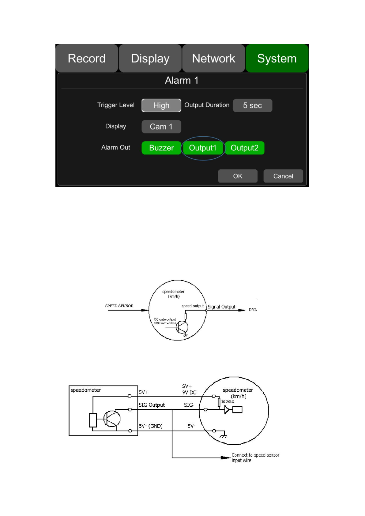
9.7 Alarm information setting................................................................................................50
9.8 Update............................................................................................................................... 53
9.9 Configuration.................................................................................................................... 57
9.10 System Info.....................................................................................................................58
10 FAQ............................................................................................................................................. 59
11 APPENDIX................................................................................................................................. 60
APPENDIXⅠ:Abbreviation & Description............................................................................... 60
APPENDIXⅡ:Accessories.........................................................................................................61
APPENDIXⅢ:Compatibility Storage List.................................................................................62

1
Specifications
4CH HD DVR
System
Operating system
Linux
Operating interface
Graphical menu operation interface(OSD)
Video permission
Administrator & user setting
Video
Video input
Max 4 x 1080P analog high definition
CVBS output
1CH 6pin aviation connector output PAL/NSTC
HDMI output
1CH type-A connector output, 1080P
Video display
1 or 4CH
Video standard
PAL: 25FPS, NTSC: 30FPS
Compression
H.264 main profile
Audio
Audio input
4 channels
Audio output
1 channel
Record format
Synchronized video & audio recording
Audio compression
ADPCM
Digital processing
& storage
Image resolution
Max 4 x 1080P(1920*1080)
Image quality
1~8 level adjustable
Video bit rate
64kbps~4Mbps/channel
Storage
56~2700MB/(channel*hour)
Playback resolution
Max 4 x 1080P(encoding & decoding at the same time)
Audio bit rate
32kbps
Storage
Max 4 x 128GB SD
Alarm
Alarm input
8 channels
Alarm output
2 channels, 1 buzzer
Motion detection
High/low sensitivity adjustable

2
Interface
for communication
IR
1 channel
RS232
1 channel
RS485
1 channel
CAN
NULL
RJ45
1 channel
USB2.0/USB3.0
USB3.0 x 1
Wireless
3G/4G
HSPDA/EVDO/FDD-LTE/TDD-LTE module optional
WIFI
optional
WIFI hotspot/AP
optional
GPS
Internal or external GPS/GLONASS module, coordinate/speed
can be encoded in video stream and upload to server by
wireless communication
G-Sensor
/Gyroscope
Available
G-Sensor
Software
Windows client
Available
iOS client
Available
Android client
Available
Web portal
Available
Electrical spec
Power supply &
consumption
DC 9~36V, less than 15w(without camera)
Operating temp. &
humidity
-20~70 degree/ <80%
Super Capacitor
Available
Clock
Built-in clock, Calendar

3
1 Main Features
Controlled by touch screen
All settings and operations could be done through the monitor if connected with
the suggested touch screen. The main function is specially needed in awkward
occasions for using mouse, like in vehicles.
Video and Audio
4 channels * 1080p, 4 video inputs with audio
1 CVBS output(1 * 6 PIN OUT), 1 HDMI(1080P), total 2 video output with audio
Recording
4-CH Video & Audio Recorder (with image resolution up to 1920*1080), and with
G-sensor data and GPS data
Multiple recording modes: power on recording, normal recording, schedule
recording, event recording (i.e., G-sensor recording, speed recording, motion
detection recording, Alarm recording 1~8, Panic button recording). Support
cyclic recording and 15 seconds pre-recording.
Recording files saved by 4 SD cards. Cyclic recording is optional.
Real-time recording of license plate numbers, bus line numbers, driving speed,
G-Sensor 3D accelerated speed, longitude and latitude, and GPS tracks.
Preview and Play Back
Support single channel, or 4 channels audio and video play simultaneously
Support searching recorded files by recording date, recording type
Able to drag the progress bar when playing back
Indicate recording status, alarm status.
Storage Types
Support SD cards (SDHC, SDXC)
The SD cards can be removed conveniently when they are not in recording or
playing status.
Backup
Support USB disk or USB hard disk for backup
Network
Transfer through LAN / Cellular / WIFI. Picture is preferred rather then video to
transmit to save cellular traffic.
LAN / WIFI / Cellular connection (default priority: LAN > WIFI > Cellular); auto
switch to LAN / WIFI connection when available to save Cellular traffic.
File uploading function via FTP function, enables users to search or download in
file list on the client.
Alarm
8 channels alarm inputs one channel buzzer output and 2 channels alarm

4
outputs
Over-speed alarm and accelerated-speed alarm
Motion detection alarm
G-sensor alarm
Video loss alarm
Panic button alarm
Charger
5V, 1.3A output from the USB interface to mobile devices, such as mobile phone.
Security
User password protection. The DVR can only be accessed with correct
password.
Support account management.

5
2 Wiring Diagram
3 Connection - Front Panel
3.1 SD card slot
SD card type: Each card Max. Capacity 128G
Insert、remove SD card
Step 1: Use the key to unlock and open front plate
Step 2: Insert SD card to SD card slot
Step 3: Close the front plate and use the key to lock
①SD Card Slot
④IR Receiver
②Ethernet(RJ45)
⑤LED Indicators
③Electronic lock
⑥HDMI output
6
3.2 Electronic lock
Close the front cover and turn the groove by the key to the icon “off”, so as to prevent
hard disk drive from moving out. Or turn to the icon “on” to open the front cover.
Electronic Lock Function:DVR will stop recording and buzzer beeps when lock is
open.
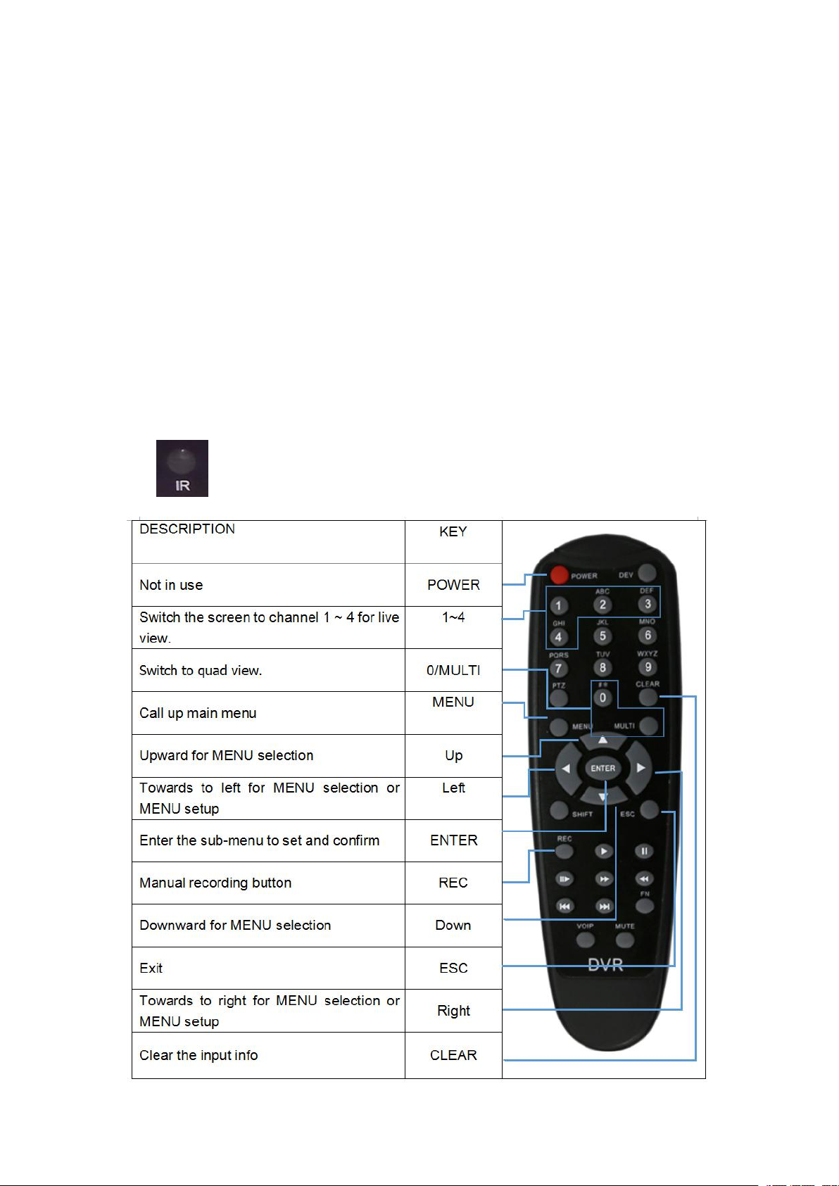
3.3 IR Receiver
The IR Receiver is for the DVR to receive command from the remote
control.
Remote control instructions:

7
3.4 LED Indicators
PWR: Red LED, lights up when DVR is powered on, and goes out when power is cut off.
RUN: Keeps on when DVR is being launched and flashes when DVR is running.
ALM: Alarm indicator. It keeps on with the record when there is Alarm-in, G-sensor activation
or motion detection or speed or panic button event alarm.
GPS: Lights up when GPS is running.
CH1~4: Lights up when corresponding camera is running.
SD1~4: Lights up when corresponding SD card is available, and flashes when recording.
CELL: Cellular indicator. It always lights up when uploading data and off when CELL has
been off or cellular module in abnormal status.
WIFI: WIFI indicator. It always lights up when uploading data and off when WIFI has been
off or WIFI module in abnormal status.
3.5 LCD monitor
EDID (Extended Display Identification Data) is automatically acquired when powered
on. DVR will read the recommended resolution of the monitor at startup. If the
recommended resolution of the monitor is 1080P, the DVR output will be 1080P;
otherwise it will be 720P.
10 inches HD monitor introduction

8
①HD monitor power button, LED red for standby mode, and green for working mode
②HDMI connector
③HDMI cable
④HD monitor 6pin aviation cable connector, with Power and Video/Audio pin.

9
The parameter list of 7/10 inches HD monitor
10 inches HD monitor
7 inches HD monitor
Description
HD 10.1"Color monitor
HD 7"Color monitor
Features
used for HD DVR
used for HD DVR
Resolution
1024 x 600 (RGB)
1024 x 600 (RGB)
Maximum Number of
Cameras
1
1
Audio input
1
1
Audio output
(loudspeaker)
1W
1W
HDMI input
1
1
VGA input
/
/
DVD input
/
/
Trigger
No
No
Max. Brightness
500 cd/m²
450 cd/m²
Contrast
600:1
800:1
Minimum Operating
Temperature
-20ºC, RH 90%
-20ºC, RH 90%
Maximum Operating
Temperature
70ºC, RH 90%
70ºC, RH 90%
Viewing Angle Monitor
U: 70/ D: 50, R/L: 70/70
U: 75/ D:75, R/L: 75/75
Mirror Function
No
No
Monitor Diameter (mm)
267mm (W) × 159.5mm
(H) × 30mm (T).
203mm (W) × 112mm (H)
× 28mm (T).
Split Screen
No
No
Volts
10-32V
10-32V
Consumption
less than 8W
less than 5W

10
Monitor remote control
How to connect the monitor
a. Connect to high-definition LCD monitor (7/10 inches HD monitor)
1.By HDMI cable
2.By 6pin aviation cable
Each of the method can display and touch control the DVR.
b. Connect to standard LCD monitor (CVBS)
1.By 4pin AVOUT on the DB44 camera cable.
There is no touch control in this way. You can use remote control to operate the
menu.
11
3.6 NO LCD monitor
If the DVR is not connected to any monitors, it will remind the customer of the
exception by Buzzer alarm .
Buzzer warning functions are as follows:
No matter what types of alarm event occur(including Alarm recording 1~8, Motion
detection recording, G-force recording,Speed recording and Panic button recording),
the Buzzer alarm will last for a while
When the Buzzer alarms intermittently, it means that the DVR is unable to record
currently.
Modes of intermittent alarm and their corresponding indications are as follows:
a. The electronic lock is open: one long Whistle and one short Whistles
b. Diskless: one long Whistle and two short Whistles
c. Disk file system exception : one long Whistle and three short Whistles
d. The disks are normal but the alarm video files fill the disks: two short Whistles and
one short Whistles
e. The disks are normal, but DVR is not recording: two short Whistles and three short
Whistles
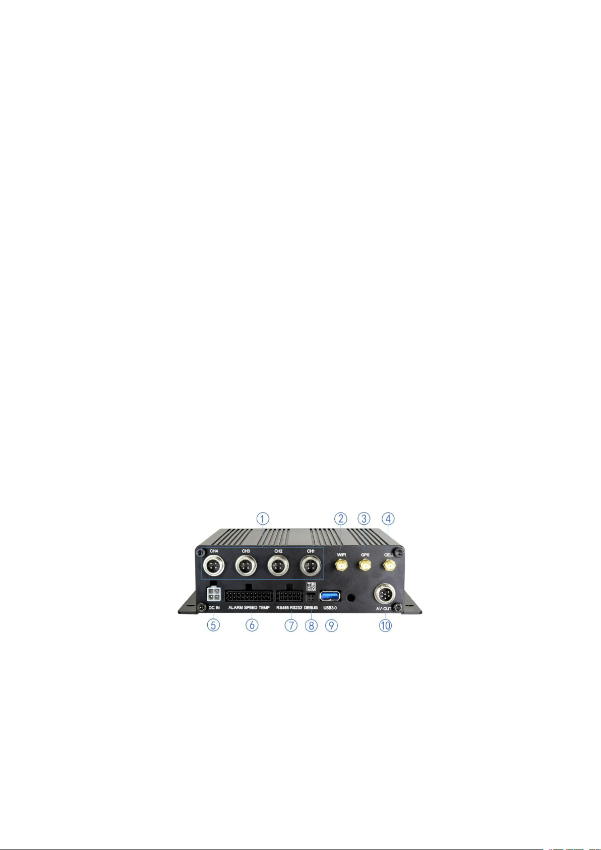
4 Connection - Front Panel
①Camera cable input
⑥Alarm-In & Alarm-Out
②Wifi Connector
⑦RS485 & RS232
③GPS Connector
⑧Debug port
④Cellular Connector, TX/RX
⑨USB3.0 connector
⑤Power input (9-36V)
⑩6pin CVBS video monitor output
12
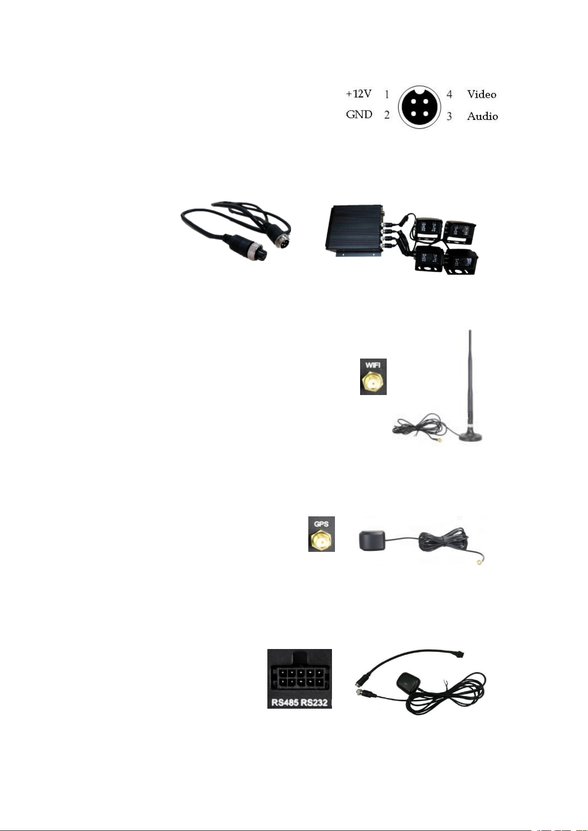
4.1 Camera cable input
Camera connection on rear panel is 4CH aerial
port. Pin-out:
Camera Connection
Four cameras can be directly, or via extension cable connected to the 4CH aerial ports on
the DVR rear panel.
4.2 Wifi Connector
Wifi antenna socket and wifi antenna, as shown in the picture.
4.3 Built-in GPS Connector
Built-in GPS antenna socket and GPS antenna, as shown in the picture.
4.4 External GPS Connector
External GPS socket and external GPS, as shown in the picture.

13
4.5 Cellular Connector, TX/RX
Cellular antenna socket and Cellular antenna, as shown in the picture.
4.6 Power input (10-36V)
Signals:
3. V+ (9~36V)
4. ACC
1. GND
2. GND
Connection Method:
Connect the ignition to ACC (the yellow wire of the power cable). Connect the “+” and “-”
pole of battery to V+ (the red wire) and GND (the black wire) of the DVR.
14
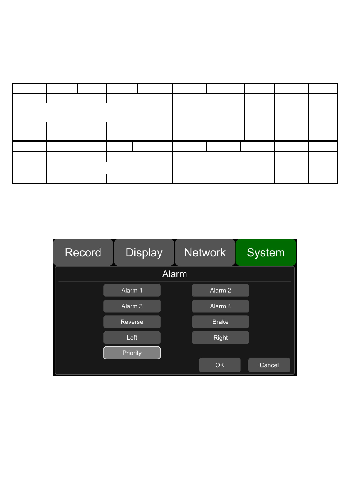
4.7 Alarm-In & Alarm-Out
Alarm, speed sensor, temperature sensor connecting cable:
1、There are 8 alarm inputs including alarm inputs 1 ~ 4, reversal input, brake input,
turn left input, turn right input, which can trigger the alarm recording. The first 4 alarm
inputs are normal alarm input defined by user. The last 4 are specific alarm input
and display cursor for each channel.
2、Alarm output 1 and Alarm output 2 are 12V output by default, which can be
used as a trigger and need to be set up to combine with alarm input . You can also
setup BUZZER for the output.
Pin-1
Pin-3
Pin-5
Pin-7
Pin-9
Pin-11
Pin-13
Pin-15
Pin-17
Pin-19
Alarm1
Alarm2
Alarm3
Alarm4
Reverse
Brake
Left
Right
Speed
GND
Alarm Input 1~4
Reverse
Input
Brake Input
Left Input
Right
Input
Speed
Input
GND
Pale Yellow
Pale
Green
Pale Pink
Pale Red
Pale Purple
Pale Brown
Pale Orange
Pale Blue
White
Black
Pin-2
Pin-4
Pin-6
Pin-8
Pin-10
Pin-12
Pin-14
Pin-16
Pin-18
Pin-20
Temp In
ADC0
PC6
PC7
PC8
Alarm Out1
Alarm Out2
GND
12V Out
Vtemp
Temp In
Tire pressure input (to be developed)
Alarm Out1
Alarm Out2
GND
12V Out
5V Out
Grey
Blue
Green
Brown
Light Green
Orange
Purple
Yellow
Red
Pink
15
3、If Alarm input 1 is active and combined with Alarm output 1, the Alarm output
1 will output a high-level voltage to trigger other device.
4、SPEED+&SPEED-
These 2 cable is for speed detection and needs to connect to speed line on vehicle.
Check the real-time vehicle speed with the vehicle speedometer:
Wiring diagram:
The vehicle speedometer is driven by the Speed sensor, see the right figure.
If the speedometer has a speed signal output, it can be connected directly to the
PIN17 of the DB26 cable and PIN18 for reference level.
If the speedometer does not have the speed signal output, then connect SIG Output
of the speedometer which is output by Speed sensor to the PIN17.
16
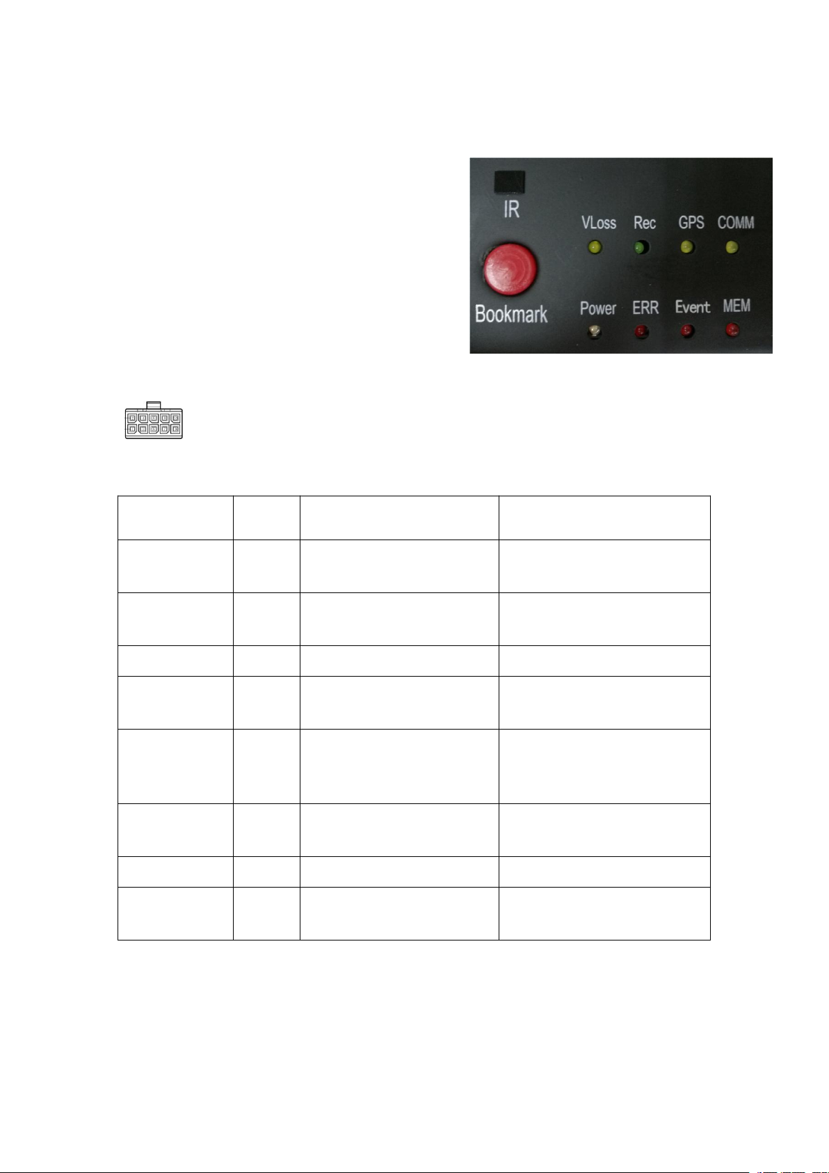
4.8 Panic button (Optional)
Overview
The LEDs are used to show the device’s
working status. But when the device is installed in
the vehicle,it is not easy to check the LED on the
front panel.Each of the LED indicates the
corresponding status. Furthermore, the panic
button on the panel make it easier to trigger alarm
for emergency or bookmarking a manual event.
Pin Definition
2*5 PIN/3.0 interface connect to the interface on panic button
LED
LED
Color
ON
OFF
VLoss
Amber
Any of the cameras have no
signal alarm
Normal Operation
Rec
Soft
green
Recording Normal driving
Not recording
GPS
Amber
GPS cannot latch
Normal Operation
Mem
Red
Storage Alarm or no
Storage device
Normal Operation
Comm
Amber
Device is not connected to
server
Normal operation or device is
not connected to server if this
feature is disabled
Power
Pale
Blue
Device has power
Device does not have power
Error
Red
Error with device
Normal Operation
Event
Red
Event-based Recording
(remains lit during Event)
Normal Operation
Button
PANIC button, printed as “Bookmark”
17
a. When pressed, will trigger a manual event
b. When pressed, will temporarily illuminate the Event LED
5 The Menu
The default setting can meet the requirement of most of users.
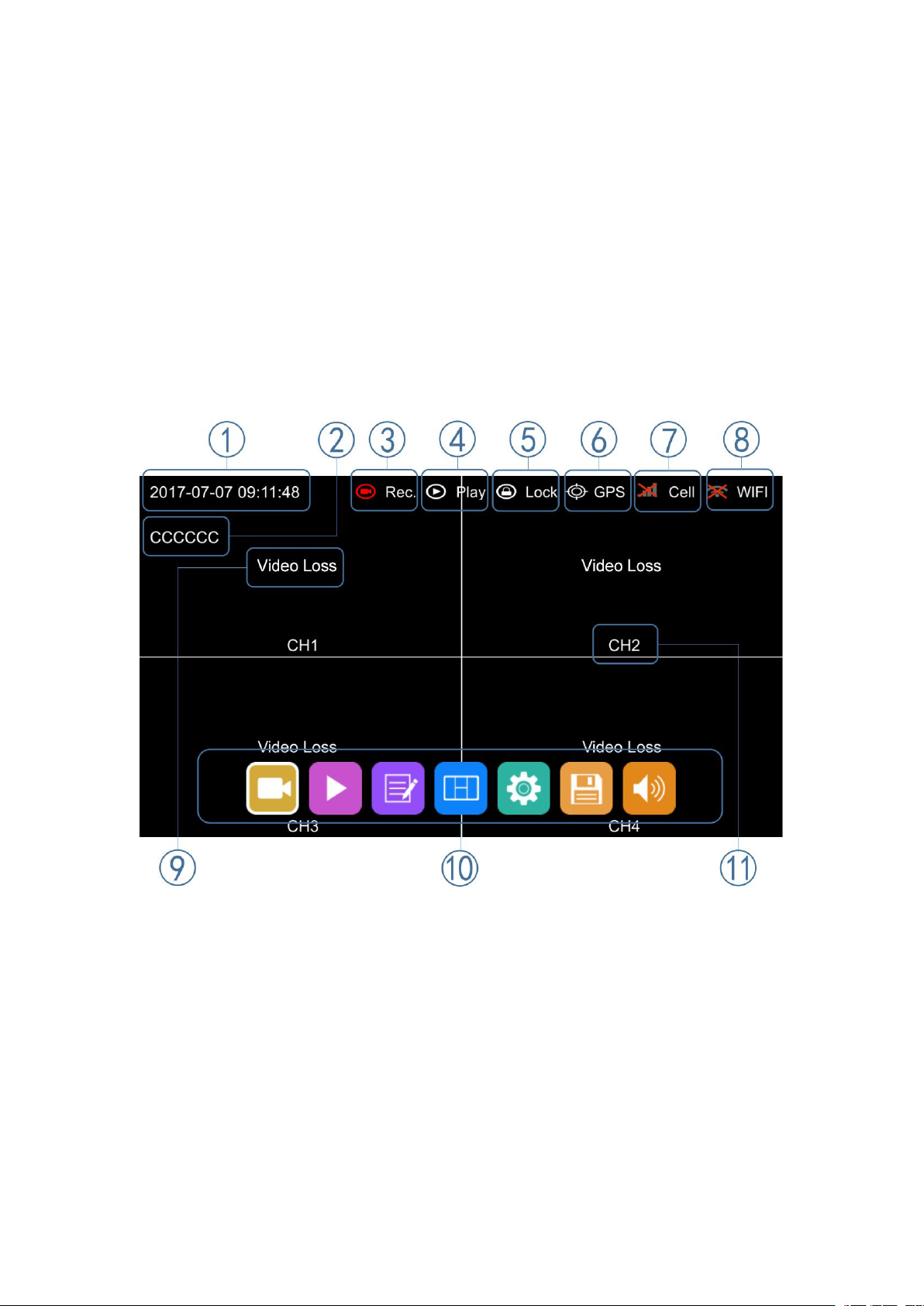
Menu Introduction
Press [MENU] on the remote or Touch the bottom area, the LOGIN page will be
displayed on the LCD screen. The Shortcut Menu will be displayed after login. If you press
[MENU] on the remote or Touch the bottom area again, the Main Menu will be displayed.
①System Time Display
②License plate number Display
③Recording Sign
The Recording Sign will turn red when recording
④Playback Sign
The Playback Sign will turn red during playback.
⑤Electronic Lock Sign
Lock indicator turns red when electronic lock is locked.
Electronic lock is different from menu lock.
⑥GPS Sign
The GPS Sign will be flashing when connecting, it will turn red when successfully
connected.
Table of contents
Other Neltronics DVR manuals


