Nematron Smart T8000 User manual

Smart T8000
Intel Bay Trail Series CPU
Fanless Embedded System
User's Manual
Revision: 2.0
Release date: July 20, 2018

Preface
1
Table of Contents
Trademark.................................................................................... 2
Environmental Protection Announcement ................................ 2
Environmental Safety Instruction............................................... 2
User’s Notice ............................................................................... 3
Manual Revision Information...................................................... 4
Part 1 Specification of Smart T8000 ........................................ 5
1.1 Overview .........................................................................................5
1.2 Smart T8000 Specification.............................................................6
Part 2 Technical Manual Of Motherboard................................ 8
2.1 Introduction of the Motherboard...................................................8
2.1.1 Feature of Motherboard........................................................8
2.1.2 Motherboard Specification...................................................8
2.1.3 Layout Diagram.....................................................................9
2.2 Hardware Installation ...................................................................13
2.2.1. Jumper Setting....................................................................13
2.2.2. Connectors and Headers....................................................16
2.3 Introducing BIOS..........................................................................21
2.3.1. Entering Setup ....................................................................22
2.3.2. BIOS Menu Screen..............................................................23
2.3.3. Function Keys .....................................................................23
2.3.4. Getting Help.........................................................................24
2.3.5. Menu Bars............................................................................24
2.3.6. Main Menu ...........................................................................24
2.3.7. Advanced Menu ..................................................................26
2.3.8. Chipset Menu ...................................................................... 34
2.3.9. Security Menu .....................................................................36
2.3.10. Boot Menu..........................................................................37
2.3.11. Save & Exit Menu...............................................................38
Part 3 Technical Manual Of Daughter Board......................... 39
3.1 Four COM ports Adapter..............................................................39
3.1.1 Feature of Four COM ports Adapter ..................................39
3.1.2 Connectors, Jumper Settings & Pin Definition:.............40
3.2 Four LAN Adapter.........................................................................42
3.2.1 Product Specifications of Four LAN Adapter ...................42

Preface
2
Trademark
Specifications and Information contained in this documentation are furnished
for information use only, and are subject to change at any time without notice,
and should not be construed as a commitment by manufacturer.
Environmental Protection Announcement
Do not dispose this electronic device into the trash while discarding. To
minimize pollution and ensure environment protection of mother earth, please
recycle.
Environmental Safety Instruction
Avoid the dusty, humidity and temperature extremes. Do not place the product
in any area where it may become wet.

Preface
3
0 to 60 centigrade is the suitable temperature. (The figure comes from the
request of the main chipset)
Generally speaking, dramatic changes in temperature may lead to contact
malfunction and crackles due to constant thermal expansion and
contraction from the welding spots’ that connect components and PCB.
Computer should go through an adaptive phase before it boots when it is
moved from a cold environment to a warmer one to avoid condensation
phenomenon. These water drops attached on PCB or the surface of the
components can bring about phenomena as minor as computer instability
resulted from corrosion and oxidation from components and PCB or as
major as short circuit that can burn the components. Suggest starting the
computer until the temperature goes up.
The increasing temperature of the capacitor may decrease the life of
computer. Using the close case may decrease the life of other device
because the higher temperature in the inner of the case.
Attention to the heat sink when you over-clocking. The higher temperature
may decrease the life of the device and burned the capacitor.
User’s Notice
Copyright of this manual belongs to the manufacturer. No part of this manual,
including the products and software described in it may be reproduced,
transmitted or translated into any language in any form or by any means
without written permission of the manufacturer.
This manual contains all information required to use this mother-board series
and we do assure this manual meets user’s requirement but will change,
correct any time without notice. Manufacturer provides this manual “as is”
without warranty of any kind, and will not be liable for any indirect, special,
incidental or consequential damages (including damages for loss of profit, loss
of business, loss of use of data, interruption of business and the like).

Preface
4
Products and corporate names appearing in this manual may or may not be
registered trademarks or copyrights of their respective companies, and they
are used only for identification or explanation and to the owner’s benefit,
without intent to infringe.
Manual Revision Information
Reversion
Revision History
Date
1.0
First Edition
June 24, 2015
2.0
Add Daughter Board
July 20, 2018

Part 1 Specification of Smart T8000
5
Part 1 Specification of Smart T8000
1.1 Overview
Fig. 1-1 Smart T8000
Fig. 1-2 Smart T8000 Rear
Fig. 1-3 Smart T8000 Front(8 COM)

Part 1 Specification of Smart T8000
6
Fig. 1-4 Smart T8000 Front(4 COM & 4 LAN)
Fig. 1-5 Smart T8000 Front(8 LAN)
1.2 Smart T8000 Specification
Type
Smart T8000
CPU
Default Configuration
Intel®Celeron®Processor J1900 2.0GHz(up to
2.41GHz,2M Cache,On Board)
Memory
Capacity
4GB DDR3L SODIMM,Max. 8GB
Storage
Default Configuration
1×500GB(With 24×7 operation)
Option
HDD(2.5″)、 SSD、mSATA
Expansion Slots
Mini PCIe
2(Full-size,one shared with mSATA)

Part 1 Specification of Smart T8000
7
PCI-e
2 ( x1 slot, at side )
SIM card holder
1
I/O Interface
Serial(DB9)
1×RS-232/422/485(rear), 1×RS-232(internal)
Extend the optional:4 or 8 RS-232/422/485
USB
3×USB 2.0(rear), 1×USB 3.0(rear)
SATA
1×SATA 2.0,1×mSATA
LAN
2×10/100/1000M
Extend the optional:4 or 8
VGA
1
HDMI
1
Audio
1×Line-Out,1×Mic
KB & MS Port
USB
Display
Video Memory
On board
Monitoring
Watchdog
0~255 Seconds
Power
Default Configuration
DC12V(Lockable)
input:90~240VAC,output:12VDC/5A/60W
adapter
Others
Cooling
Fanless
Construction
Aluminum & steel
Mounting
Desktop、Wall Mount、Din Rail
Dimensions(W×H×D)
185mm×48mm×165mm
Weight
2.4kg(without adapter)
Environmental
Operating Temperature
0~60℃
Storage Temperature
-10~70℃
Relative Humidity
10~90%(non-condensing)
Certification
CE,FCC

Part 2 Technical Manual Of Motherboard
8
Part 2 Technical Manual Of Motherboard
2.1 Introduction of the Motherboard
2.1.1 Feature of Motherboard
Onboard Intel®Bay Trail Series Processor, with low power consumption
never denies high performance
Support 1×DDR3L 1066/1333 MHz SO-DIMM, up to 8GB
Support 2×full-size Mini-PCIE connector
Support 1×full-size m-SATA (share with Mini-PCIE)
Support 1×2.5’’ SATAII hard disk driver device (3Gb/s)
Support USB 3.0 data transport demand
Support VGA & HDMI dual display output
Support CPU Over-Temperature protection
Support CPU Over-Current/Under Voltage protection
Amplifier implement to support 3W Speaker
Support CPU Smart FAN
Compliance with ErP standard
Support Watchdog function
2.1.2 Motherboard Specification
Spec
Description
Design
6 layers; PCB size: 10×16.7 cm
Embedded CPU
Integrated with Intel®Bay Trail-D/M/I series CPU
Memory Slot
1×DDR3L SODIMM Slot for un-buffered DDR3L
1066/1333 MHz SDRAM, expandable to 8GB in
total
Expansion Slot
2×Full-size Mini-PCIE slot (MPE1/ MMPE1)
2×PCIE x1 slot by sideway (PCIE1/PCIE2)
LAN Chip
Integrated with 2×Intel I211AT PCI-E Gigabit LAN
chips
Support Fast Ethernet LAN function of providing
10/100/1000Mbps Ethernet data transfer rate
Storage
1×3+7 pin HDD Connector for 2.5″SATAHDD
1×Full-size MSATA slot (MMPE1, share with

Part 2 Technical Manual Of Motherboard
9
Mini-PCIE slot)
BIOS
AMI 64MB Flash ROM
Rear I/O
1×12V DC-in power Jack
1×System reset button
1×USB 3.0 port
3×USB 2.0 port
1×HDMI port
2×RJ-45 LAN port
1×COM1 serial port (COM1 supports RS422/485
function)
1×VGA port
1×Audio Line Out port
1×Audio MIC port
Internal I/O
1×2-Pin internal 12V DC-in power connector
1×CPUFAN header
1×SYSFAN header
1×Front panel header
1×4-pin USB 2.0 header (Expansible to 1×USB
2.0 port)
1×GPIO_CON header
1×SPEAK_CON header
1×J1 jumper & header block
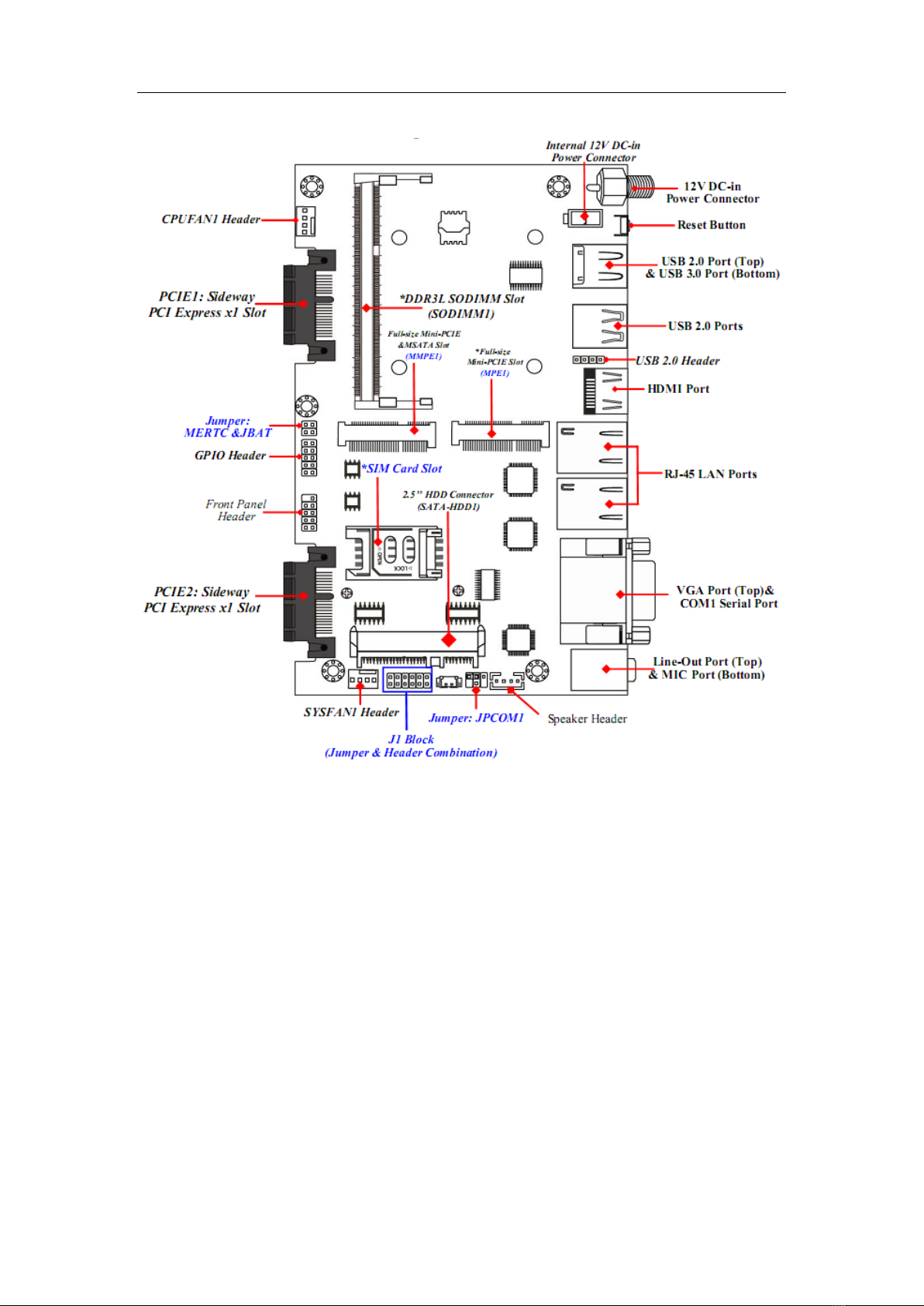
2.1.3 Layout Diagram
Rear IO Panel Diagram:
Warning!
The board has a 12V DC-in power connector (DCIN) in I/O back panel and
an internal ATX12V (ATX2P) power connector. User can only connect one
type of compatible power supply to one of them to power the system.
Part 2 Technical Manual Of Motherboard
10
Motherboard Internal Diagram-Front Side
Note: 1.The memory module should be DDR3L 1.35V SODIMM and not exceeding 8GB
total capacity. 2. SIM card slot only work when compatible SIM card installed & 3G LAN
card installed in MPE1 Mini-PCIE slot.

Part 2 Technical Manual Of Motherboard
11
Motherboard Internal Diagram-Back Side
*Note: CPU is the most important part of the board and very fragile to any
possible harm. Make sure that there is no damage to the CPU during any
installation procedures!
Jumper
Jumper
Name
Description
JBAT_MERTC
Pin (1&3): Clear ME Function Setting
Pin (2&4): Clear CMOS RAM Function
Setting
4-Pin Block
J1
Pin (1&2): ATX Mode / AT Mode Select
Pin(3&4): Case Open Message Display
Function
Pin (9&10): ME Security Measure Function
12-Pin Block
*Intel CPU
Part 2 Technical Manual Of Motherboard
12
Select
JPCOM1
COM1 Port Pin9 Function Select
4-Pin Block
Connectors
Connector
Name
DCIN
12V System DC–in Power Jack Connector
ATX2P
Internal 12V System DC–in Power Connector
USB1
Top: USB 2.0 Port Connector
Bottom: USB 3.0 Port Connector
USB2
USB 2.0 Port Connector×2
HDMI
HDMI Port Connector
LAN2/LAN1
RJ-45 LAN Port Connector×2
VGA
Video Graphic Attach Connector
COM1
Serial Port Connector
AUDIO
Top: Audio Line Out Connector
Bottom: Audio MIC Connector
SATA-HDD1
3+7 pin HDD Connector for 2.5″SATA HDD
CPUFAN1
CPUFAN Connector
SYSFAN1
SYSFAN1 Connector
Headers
Header
Name
Description
JW_FP
Front Panel Header(PWR LED/ HDD
LED/Power Button /Reset)
9-pin Block
FP_USB1
USB 2.0 Header
4-pin Block
GPIO_CON1
GPIO Header
10-pin Block
SPEAK_CON1
Speaker Header
4-pin Block
J1
Pin(5&6):LAN2 Activity LED Header
Pin(7&8):LAN1 Activity LED Header
Pin(11&12):SPDIF_Out Header
12-pin Block
Part 2 Technical Manual Of Motherboard
13
2.2 Hardware Installation
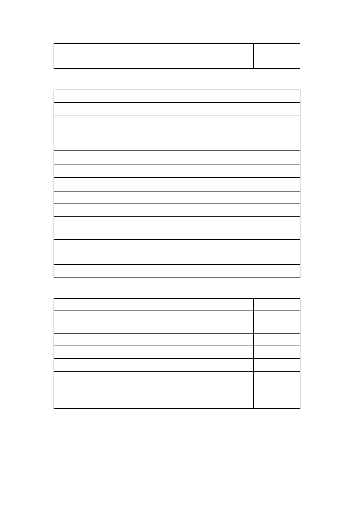
2.2.1. Jumper Setting
Pin (1&3) of JBAT_MERTC (4-pin): Clear ME Function Setting
Pin(1&3) of JBAT_MERTC→Clear ME
1-3 Open: Normal(Default);
1-3 Closed: Clear ME.
Pin(2&4)of JBAT_MERTC (4-pin): Clear CMOS Setting
Pin (2&4) of JBAT_MERTC→Clear
CMOS
2-4 Open: Normal(Default);
2-4 Closed: Clear CMOS(One Touch).

Part 2 Technical Manual Of Motherboard
14
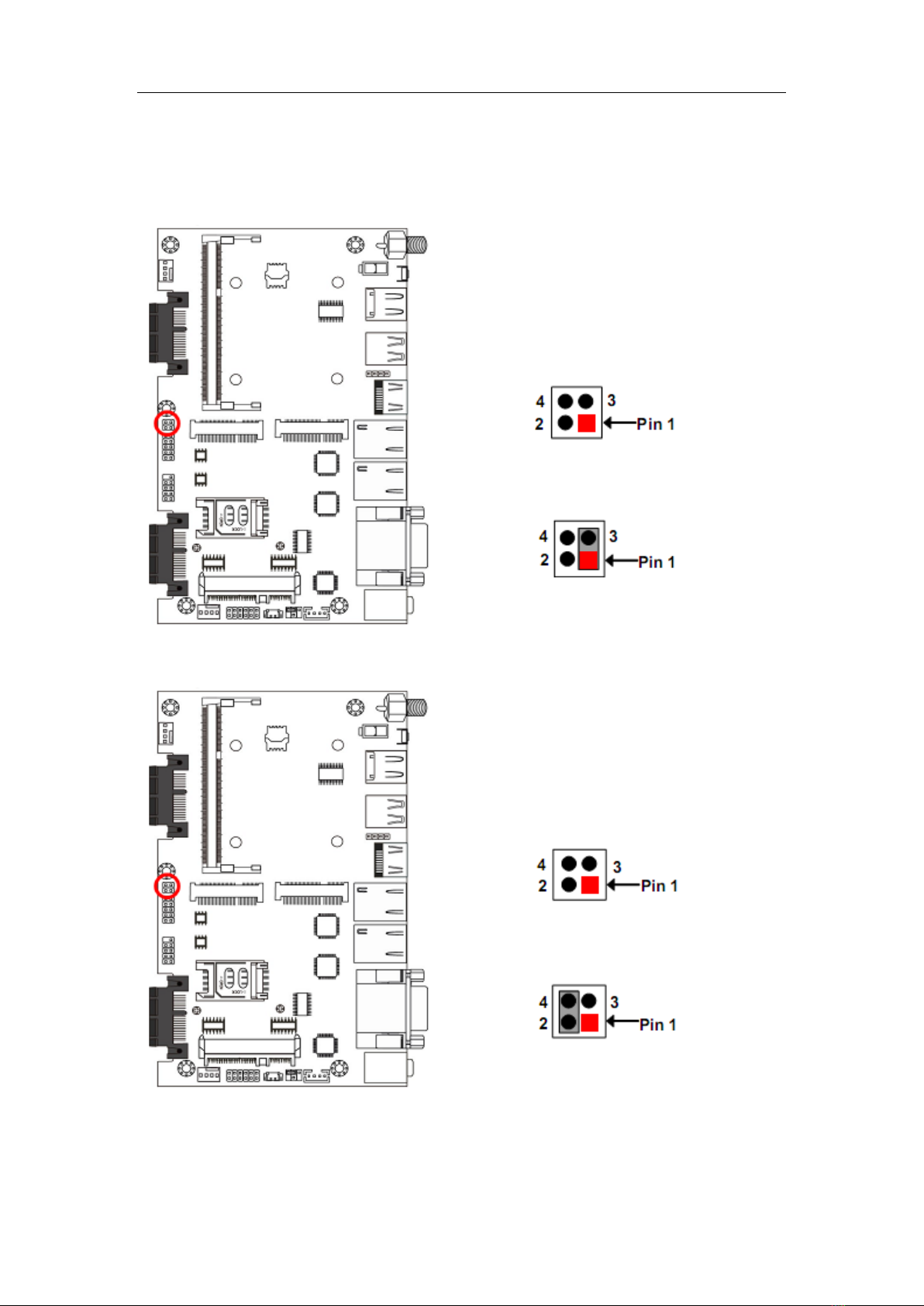
Pin (1&2) of J1 (12-pin): ATX Mode/AT Mode Select
Pin (1&2) of J1→ATX/AT Mode Select
2-4 Open: Normal(Default);
2-4 Closed: Clear CMOS(One Touch).
*ATX Mode Selected: Press power button to power on after power input
ready;
AT Mode Selected: Directly power on as power input ready.
Pin (3&4)of J1 (12-pin):Case Open Message Display Function Select
Pin (3&4) of J1→Case Open
3-4 Open: Normal(Default);
3-4 Closed: Case Open Function.
Pin (3&4) Closed:When Case open function pin short to GND, the Case open
function was detected. When Used, needs to enter BIOS and enable ‘Case

Part 2 Technical Manual Of Motherboard
15
Open Detect’function. In this case if your case is removed, next time when
you restart your computer, a message will be displayed on screen to inform you
of this.
Pin (9&10) of J1 (12-pin): ME Security Measure Function Select
Pin (9&10)of J1→ME Security
Function Select
9-10 Open: Enable Security Measures
in the Flash Descriptor(Default);
9-10 Closed: Disable Security
Measures in the Flash Descriptor
(Override).
JPCOM1 (4-pin): COM1 Port Pin9 Function Select
JPCOM1→COM1 Port Pin-9
2-4 Closed: RI=RS232(Default);
3-4 Closed: RI= 5V;
4-6 Closed: RI= 12V.

Part 2 Technical Manual Of Motherboard
16
2.2.2. Connectors and Headers
Connectors
(1) Rear I/O Connectors
*Refer to Page-3: Rear IO Panel Diagram.
Icon
Name
Function
12V DC-in Power
Connector
For user to connect compatible power
adapter to provide power supply for the
system.
USB 2.0 Port
To connect USB keyboard, mouse or
other devices compatible with USB
specification.
USB 3.0 Port
To connect USB keyboard, mouse or
other devices compatible with USB
specification. USB 3.0 ports supports
up to 5Gbps data transfer rate.
HDMI Port
To connect display device that support
HDMI specification.
RJ-45 LAN Port
This connector is standard RJ-45 LAN
jack for Network connection.
VGA Port
To connect display device that support
VGA specification.
RS232/422/485
Serial Port
Mainly for user to connect external
MODEM or other devices that supports
Serial Communications Interface.
Audio Connectors
GREEN:Line-out Connector
PINK : MIC Connector
(2) COM1 (9-pin Block): RS232/422/485 Serial Port
COM1 port can function as RS232/422/485 serial port. In normal settings
COM1 functions as RS232 port. With compatible COM cable COM1 can
function as RS422 or RS 485 port.
User also needs to go to BIOS to set ‘Transmission Mode Select’for COM1
(refer to Page 22)at first, before using specialized cable to connect different
pins of this port.

Part 2 Technical Manual Of Motherboard
17
For RS422 Mode
For RS485 Mode
(3) ATX2P (2-pin Block): Internal 12V DC-in Power Connector
Pin.
Definition
1
GND
2
+12V DC_IN

Part 2 Technical Manual Of Motherboard
18
(4) CPUFAN1 (4-pin): CPUFAN Connector
(5) SYSFAN1 (4-pin): SYSFAN Connector

Part 2 Technical Manual Of Motherboard
19
Headers
(1) JW_FP (9-pin): Front Panel Header
(2) FP_USB1 (4-pin): USB 2.0 Port Header
Table of contents
Other Nematron Switch manuals

Popular Switch manuals by other brands


ZyXEL Communications
ZyXEL Communications Dimension ES-4124 user guide

Belkin
Belkin F5U303 Quick installation guide

CyberData
CyberData 11187 Installation quick reference

Advantech
Advantech ADAM-6520 Series user manual

cable matters
cable matters 202046 quick start guide

Alps Electric
Alps Electric SKRN Series Specifications


