Neol ePowerSwitch-1 Guard User manual

V.03/2004
ePowerSwitch-1 Guard
Power Management and
Server Supervision
User's Guide

ePowerSwitch-1 Guard User's Guide
ePowerSwitch-1 Guard
User's Guide
ePowerSwitch-1 Guard is a power control unit with a built-in Web server, an Ethernet and a
serial RS232 connection. It enables to control the power supply of a power outlet either remotely
through a network (Intranet or Internet) or locally through its serial RS232 connection.
Its special Pinging and Scanning functions also allow the ePowerSwitch-1 Guard to supervise IP
devices (servers, routers...) and automatically reboot them in case of lock-up.
Chapters
1. Safety instructions to be read before use!
2. Configuration of the ePowerSwitch
3. Configuration using the ePowerSwitch Finder program
4. Configuration using a Web browser
5. Configuration using a Terminal connection
6. Security parameters configuration
7. Ping and Port Scanning
8. Serial port pin configuration
9. Command the state of the socket through a Web browser
10.Command the state of the socket through a serial connection
11.Technical characteristics
12.Statement of Conformity

ePowerSwitch-1 Guard User's Guide
1. Safety instructions: To be read before use!
The ePowerSwitch devices can only be installed by qualified people with the following
installation and use instructions. The manufacturer disclaims all responsibility in case of a
bad utilisation of the ePowerSwitch devices and particularly any use with equipments that
may cause personal injury or material damage.
This equipment is designed to be installed on a dedicated circuit that must have a circuit
breaker or fuse protection.
The electrical power socket used to plug the power cord of the ePowerSwitch device must be
close to the ePowerSwitch device and easily accessible.
Check that the power cord, plug and socket are in good condition.
The ePowerSwitch device can only be connected to three-wire 230 VAC (50-60Hz) socket.
Always plug the ePowerSwitch devices into properly grounded power sockets (two poles plus
ground).
Never exceed 10 Amp total load.
If you have to replace an external fuse of an ePowerSwitch device, never use another type of
fuse than 10A/250V T.
The ePowerSwitch devices are intended for indoor use only. Do NOT install them in an area
where excessive moisture or heat is present.
Always disconnect the power cord of the ePowerSwitch device if you want to intervene on the
ePowerSwitch device or on the equipment powered from the ePowerSwitch device.
The power outlet of the ePowerSwitch devices is not a circuit breaker! If you want to
intervene on equipment connected to an ePowerSwitch device you must disconnect this
equipment from the ePowerSwitch device.
The ePowerSwitch devices contain potentially hazardous voltages. Do NOT attempt to
disassemble them.
The ePowerSwitch devices contain no user serviceable parts and repairs are to be performed
by factory trained service personnel only.

ePowerSwitch-1 Guard User's Guide
2. Configuration of the ePowerSwitch
To use the ePowerSwitch on your network you must first configure its network parameters. Ask
your network administrator for the parameters to use.
There are three different methods to configure the ePowerSwitch:
Method 1:
Through a network using the ePowerSwitch Finder Program (on the delivered CD).
It is the simplest and fastest configuration method if you use Windows as operating system. We
suggest that you use this program at least during the first configuration: it allows you to
configure your ePowerSwitch through your local network even if its network parameters (IP
Address, Subnet mask and Port) are not compatible with those of your PC or your local
network.
If you decide to use this method you can directly go to §3 "Configuration using the
ePowerSwitch Finder program".
Method 2:
Through a network using a Web browser (Internet Explorer > 6.0 and Netscape > 6.1).
This method can only be used if the network parameters of the ePowerSwitch (IP Address,
Subnet mask…) have already been configured using either the ePowerSwitch Finder program
(Method 1) or a Terminal program (Method 3).
For the first configuration you can also change the Network parameters of your PC according to
the default settings of the ePowerSwitch.
Default Network setting of the ePowerSwitch:
IP Address: 192.168.100.100
Mask: 255.255.255.0
Port: 80
If you decide to use this method you can directly go to §4 "Configuration using a Web browser".
Method 3:
Through a RS232 serial connection using a Terminal connection (see §7 "serial port pin
configuration" for the configuration of the serial interface connector).
If you use a PC, use the serial cable supplied with the product and a Terminal program such as
HyperTerminal from Microsoft.
If you decide to use this method you can directly go to §5 "Configuration using a Terminal
connection".
ePowerSwitch-1 Guard User's Guide
3. Configuration using the ePowerSwitch Finder program
Remarks:
∇ The ePowerSwitch and the PC used to configure it have to be connected on the same
segment of the network. The protocol of this program can not be routed so it can not be used
to configure the ePowerSwitch through a WAN or the Internet.
∇ This program does not work if the administrator has deactivated it in the configuration of the
ePowerSwitch (for security reasons for example).
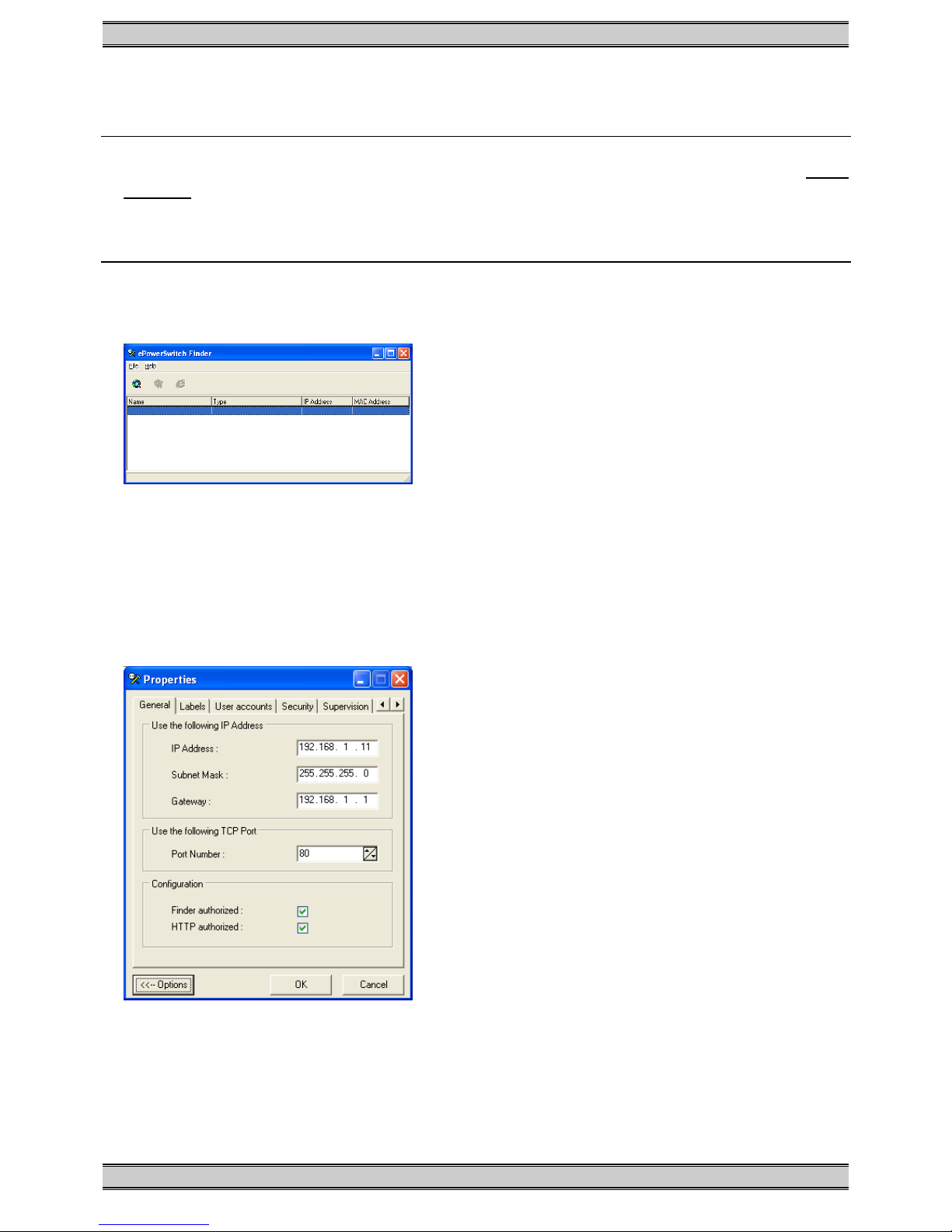
1. Start the program ePS-Finder.exe on the CD-ROM.
The ePowerSwitch Finder window appears.
2. In the tool bar click on the first left button or choose the File/Scan Menu.
The program browses the segment on which is connected your PC and displays the name,
the type, the IP and MAC Address of the connected ePowerSwitch.
3. In the tool bar click on the second left button or choose the File/Configure Menu.
The properties dialog box appears and you can now configure all parameters. To configure
all other parameters click on the Options button on the bottom of the dialog box.

ePowerSwitch-1 Guard User's Guide
General Tab
This tab is used to attribute all the network parameters.
Labels Tab
This tab is used to attribute a name to the device and its controlled power socket.
User Accounts Tab
This tab is used to attribute a name and a password to the administrator and the user.
Security Tab
This tab is used to define addresses which are authorised or denied access to the
ePowerSwitch over the Network. For all details about this features please refer to chapter 6
"Security parameters configuration".
Supervision Tab
This tab is used to define the IP address of the device which has to be supervised and all the
corresponding parameters. The ePowerSwitch can supervise IP devices by pinging a specific IP
address and/or by scanning a specific port number.
Remark: the supervision function works only if the power outlet is ON.
Options Tab
This tab is used to define the default status of the controlled power socket after power up and
the delay for the restart function.
Miscellaneous Tab
This tab indicates the number of Power Ups and switching cycles from OFF to ON.

ePowerSwitch-1 Guard User's Guide
4. Configuration using a Web browser
Remarks:
∇ In order to be able to access the Web server of the ePowerSwitch, you must before have
configured its network parameters (ask your network administrator).
∇ The configuration using a Web browser does not work if the administrator has deactivated it
in the configuration of the ePowerSwitch (for security reasons for example).
∇ The Web server of the ePowerSwitch works with Internet Explorer Version 6.0 or higher and
with Netscape Version 6.1 or higher.
1. Start your Web browser.
2. Type the IP address of your ePowerSwitch. The browser displays the authentication dialog
box.
3. Enter the administrator name (default value = admin) and the administrator password (default
value = admin) and click on OK.
The home page is displayed, allowing you to configure all the parameters of the
ePowerSwitch.

ePowerSwitch-1 Guard User's Guide
Home Tab
This tab is used to switch on, off and restart the controlled power socket and to configure the
ePowerSwitch.
General Tab
This tab is used to:
- attribute a label to the ePowerSwitch and its controlled power socket
- define all IP parameters (IP Address, Subnet mask, Gateway and Port number)
- enable or disable the use of the ePowerSwitch Finder program
- enable or disable the configuration of the ePowerSwitch through HTTP.
Security Tab
This tab is used to define the Name and the Address of the Administrator and the User.
It’s also used to set the Network Security Masks. For all details about this features, please refer
to chapter 6 "Security parameters configuration".
Supervision Tab
This tab is used to define the IP Address of the device that has to be supervised and all the
corresponding parameters. The ePowerSwitch can supervise IP devices by pinging a specific IP
address and/or scanning a specific port number.
Remark: the supervision function works only if the power outlet is ON.
Options Tab
This tab is used to define the default status of the controlled power socket after power up and
the delay for the restart function. This tab also indicates the number of Power Ups and the
number of switching cycles from OFF to ON.

ePowerSwitch-1 Guard User's Guide
5. Configuration using a Terminal Connection
The RS232 serial port of the ePowerSwitch can be used to control its power socket and to
configure its Web server.
To configure the Web server:
1. Use the supplied RS232 serial cable to connect the ePowerSwitch-1 to an available serial
port of your PC.
2. Run a terminal program such as Windows HyperTerminal or the MicroTerminal program on
the CD (folder miscellaneous).
3. Configure the appropriate serial port with the following settings:
9.600 bauds, 8 bits, no parity, 1 stop bit and no flow control.
If you use the MicroTerminal program on the CD (folder miscellaneous) you only have to
choose the used serial port, this program is already configured at 9.600 bauds, 8 bits, no
parity, 1 stop bit, no flow control.

ePowerSwitch-1 Guard User's Guide
4. From your computer, press <ENTER> until the prompt «>» appears on your screen.
(the ePowerSwitch is now in Command mode and is waiting for commands to switch the
power socket).
5. Press the <TAB> key on your keyboard.
The Configuration menu appears on your screen and the ePowerSwitch is now in
Configuration mode. Follow the menu to configure the Web server of your ePowerSwitch.
ePowerSwitch 1 Guard
Version: 1.2.0.2
Commands :
Display
/DS Display Socket State
Control
/SS Switch the socket
Configuration
/NP Network Parameters Setting
/PS Passwords Setting
/NS Device and Socket Name Setting
/SP Socket Parameters Setting
/SU Device Supervision Setting
/IS IP Security Setting
/RS Restart the Device
Enter Selection
>
All commands start with the slash «/»
(ex.: type the command /NP to go to the Network Parameters setting menu.
To display the current menu again, press <ENTER>.
To go to the previous menu and to display it, press <ESC>.
Remark: to leave the configuration mode, type the restart command /RS. This is particularly
important if you want to control the power outlet later through the serial connection.

ePowerSwitch-1 Guard User's Guide
6. Security parameters configuration
Explanations about the masks settings:
∇ Each mask can be an IP address or a range of IP addresses.
∇ Each mask allows you to authorise or deny access to the Web server of the ePowerSwitch to
specific addresses or to specific ranges of addresses.
∇ Each mask can be activated or deactivated (without function in this case).
∇ Each IP address consists of a series of four eight-bit numbers. The number 255 is used as a
wildcard, so it replaces all others.
∇ Masks are listed in order of descending priority; so Mask 1 has the highest priority.
∇ Masks have a cumulative effect; high priority masks supersede the effect of lower priority
masks.
Example 1:
⇒ Deny access to all IP addresses except 192.168.001.015
Mask IP Address Permit Deny Activated
#1 192.168.001.015 99
#2 255.255.255.255 99
Example 2:
⇒ Permit access only to IP addresses beginning with 192.
Mask IP Address Permit Deny Activated
#1 192.255.255.255 99
#2 255.255.255.255 99

ePowerSwitch-1 Guard User's Guide
Example 3:
⇒ Permit access only to IP addresses beginning with 192
⇒ Deny access to IP address 192.168.001.010
Mask IP Address Permit Deny Activated
#1 192.168.001.010 99
#2 192.255.255.255 99
#3 255.255.255.255 99
Example 4:
⇒ Permit access to IP addresses beginning with 192
⇒ Deny access to address 192.168.001.010
⇒ Permit access to IP addresses beginning with 217.128.103
Mask IP Address Permit Deny Activated
#1 192.168.001.010 99
#2 192.255.255.255 99
#4 217.128.103.255 99
#3 255.255.255.255 99

ePowerSwitch-1 Guard User's Guide
7. Ping and Port Scanning
ePowerSwitch has two methods to check whether an IP equipment (PC, server, router,
Webcam...) is still alive.
Ping
The first method uses the well-known Ping command whereby a request is sent to a specific IP
address. The Ping command, which is an echo request, enables you to determine through an
ICMP protocol (Internet Control Message Protocol) if an IP device is available on the network. If
the system reacts to this request, ePowerSwitch knows that the TCP/IP connection is
established. If the system does not react to one or several requests, ePowerSwitch can
automatically switch off and after a specified delay switch again on the IP equipment (Reboot).
Port Scanning
The second method uses the Port Scan command to test a specific TCP/IP port. In other words,
this command allows you to find out if a specific protocol is available on a server (for example
HTTP, FTP, Telnet, SMTP, POP...). ePowerSwitch simply tries a connection to a specific server
port. If the connection is possible, ePowerSwitch knows that a server program is running there.
If the connection is not possible, ePowerSwitch can automatically switch off and after a
specified delay switch again on the IP equipment (Reboot).
Remarks:
− The Ping and Scan function can be used separately or together.
− The network route between ePowerSwitch and the IP device to supervise should be as direct
as possible, so do not use unnecessary routers and complex wiring between them. A
problem on a router or the wiring could reboot the IP device to supervise.
− Execute several Pings and/or Scans before running the Reboot function. It could be possible
that the IP device to supervise doesn't respond although the IP device is still working.
− Choose a realistic supervision cycle. One second is possible, however it’s not necessary to
overload the network with Pings and Scans requests.
Recommended values:
Interval between Requests: 10 sec or more
Number of unsuccessful Requests before Reboot: 3 or more
Delay before Reboot: 10 sec or more
Delay before first Request after Reboot: 120 sec or more

ePowerSwitch-1 Guard User's Guide
8. Serial port pin configuration
The serial connection uses a SUB-D9 connector with the following configuration:
Pin 2 = TxD (transmit data to the PC)
Pin 3 = RxD (receive commands)
Pin 5 = GnD
Parameters: 9600, n, 8, 1 without flow control.

ePowerSwitch-1 Guard User's Guide
9. Command the state of the socket through a Web browser
1. Start your Web browser
Type the IP address of your ePowerSwitch.
The browser displays the authentication dialog box.
2. Enter a user name and its corresponding password.
− If you enter the administrator name (default value = admin) and the administrator password
(default value = admin) and click OK, you will be able to control the socket status and also
to configure all the parameters of the ePowerSwitch.
− If you enter the user name (default value = user1) and the user password (default value =
user1) and click OK, you will be able to control the socket status only.
The button Power allows you to switch the socket ON and OFF.
The button Restart allows you to switch the socket OFF. It will be automatically switched on
after the delay fixed by the administrator during the configuration (default value is 5 sec).
Under the command button is displayed the state of the IP supervision.
− If the supervision function is deactivated (can be done by the administrator only) the
message «Supervision deactivated» is displayed.
− If the supervision function is activated (can be done by the administrator only) the message
«Supervision activated» is displayed.
Remark: if you switch the socket OFF, the supervision function is temporarily deactivated
and the message "Supervision temporarily deactivated" is displayed.

ePowerSwitch-1 Guard User's Guide
10. Command the state of the socket through a serial connection
The socket of the ePowerSwitch-1 can also be controlled using a simple ASCII protocol over a
RS232 serial connection.
To control the power socket:
1. Use the supplied RS232 serial cable to connect the ePowerSwitch-1 to an available serial
port of your PC.
2. Run a terminal program such as Windows HyperTerminal or the MicroTerminal program on
the CD (folder miscellaneous).
3. Configure the appropriate serial port of your Terminal program with the following settings:
9.600 bauds, 8 bits, no parity, 1 stop bit, no flow control.
If you use the MicroTerminal program on the CD (folder miscellaneous) you have only to
choose the used serial port, this program is already configured at 9.600 bauds, 8 bits, no
parity, 1 stop bit, no flow control.
4. On your computer, press <ENTER> until the prompt «>» appears on your screen.
(the ePowerSwitch is now in command mode and is waiting for commands to switch the
power socket).
Remark: the power outlet of the ePowerSwitch can only be controlled if the ePowerSwitch is in
Command mode and NOT in Configuration mode. If you are in Configuration mode, type the
/RS command to leave this mode. By default, the ePowerSwitch is in Command mode after a
power up.
Use the following commands:
p=1 and press <ENTER> to switch the socket ON
p=0 <ENTER> to switch the socket OFF
p=r <ENTER> to restart the socket
p=t <ENTER> to toggle the socket
The ePowerSwitch accepts lower case and upper case commands.
The version of the firmware can be displayed by typing "?" followed by <ENTER>.

ePowerSwitch-1 Guard User's Guide
11. Technical data
Network standards IEEE 802.3, 10BASE-T
Network protocols TCP/IP, HTTP
Network connection RJ-45 connector for UTP CAT5
Max. network cable length 100 meters (not included)
Serial connection RS232, SUB-D 9 female
Nominal input voltage 230 V/50Hz
Input power socket IEC-320
Output voltage 230 V/50Hz
Output power socket IEC-320
Maximum total current 10 A
Fuse 10 A(T)
LED’s 1 for Power and Network Traffic
1 for the socket status
Operating temperature 0°C to +40°C
Operating humidity 10% to 80%
Dimensions 185 X 103 X 43 mm
Weight 0,8 Kg
Approvals CE, EN55022 & EN55024
Guarantee 2 years repair or replace

ePowerSwitch-1 Guard User's Guide
12. Statement of Conformity
STATEMENT OF
CONFORMITY
Application of Council Directives: 89/336/EEC, 92/31/EEC,
73/23/EEC, 93/68/EEC
Standards to Which Conformity declared: EN 60950, EN 55022,
EN 55024
Manufacturer's Name and Address: NEOL SA
4 Rue Nationale
67800 BISCHHEIM -FRANCE
Type of Equipment: Power Control Unit
Type Designation: ePowerSwitch-1 Guard
Reference: EPS 1
Years of Manufacture: 2003
We, the undersigned, hereby declare that the equipment specified above
conforms to the above directives.
Bischheim, 4th December 2003
Paul REYSER,
General Manager
NEOL SA

ePowerSwitch-1 Guard User's Guide
All modifications reserved
EPS-1G UG EN.doc
03/03/2004
Table of contents
Other Neol Switch manuals


Popular Switch manuals by other brands

Cables to Go
Cables to Go Port Authority2 user manual

A SYSTEMS
A SYSTEMS AV800HD user manual

EUCHNER
EUCHNER CES-I-BR Series operating instructions

Penguin
Penguin Edge RTM-ATCA-F140 quick start guide

Chamberlain
Chamberlain K71-33445 quick start guide

HPP Enterprises
HPP Enterprises FlexNetwork 7500 Series Configuration guide


Ametek
Ametek Magnetrol3 Series Installation and operating manual

schmersal
schmersal ZF 232 Series operating instructions

SMC Networks
SMC Networks ZSE20AF X576 Series Operation manual

Micas
Micas M2-S6510-48V8C Hardware installation and reference guide

Aeronix
Aeronix GES user manual

GarrettCom
GarrettCom Magnum CSG14 Installation and user guide