Neol ePowerSwitch 8XM R2 User manual

e
P
Version 0
9
P
o
w
9
/2009
w
er
S
S
wi
U
s
tch
s
er g
u
8X
u
ide
M
R
R
2
ww
w
w
.neol.com

1
© Copyright by NEOL S.A.S - 4 Rue Nationale, 67800 BISCHHEIM, France
Printed in France
All rights reserved. No part of this documentation, accompanying software or other components of the
described product may be reproduced or transmitted in any form or by any means, electronic or mechanical,
including photocopying and recording, for any purpose other than the personal use of the purchaser without
the express written permission of NEOL S.A.S.
This documentation, the ePowerSwitch 8XM, its peripherals, accessories and accompanying software were
produced with great care, yet errors are possible.
NEOL S.A.S assumes no responsibility for errors within the documentation, the hardware or the software.
NEOL S.A.S reserves the right to change programs or the documentation from time to time without informing
the user, errors and omissions excepted.
Trademarks
Neol and ePowerSwitch are registered trademarks of NEOL S.A.S. All other brand names and
product names used in this book are trade names, service marks, trademarks, or registered
trademarks of their respective owners.

2
CONTENTS
SAFETY INSTRUCTIONS: To be read before use!...................................................................................... 3
1. DESCRIPTION.......................................................................................................................................... 4
1.1 Diagram............................................................................................................................................... 4
1.2 Package list......................................................................................................................................... 7
2. INSTALLATION......................................................................................................................................... 8
3. CONFIGURATION .................................................................................................................................... 9
3.1. Configuration through the LAN using the Finder program ................................................................. 9
3.2. Configuration through an RS232 Terminal connection.................................................................... 11
3.3. Configuration through the LAN using a standard Browser............................................................... 11
3.3.1. General / IP configuration ...................................................................................................... 12
3.3.2. General / System time............................................................................................................ 14
3.3.3. General / SMTP...................................................................................................................... 15
3.3.4. General / SNMP..................................................................................................................... 16
3.3.5. General / Tools....................................................................................................................... 17
3.3.6. Settings / Accounts................................................................................................................. 18
3.3.7. Settings / Groups.................................................................................................................... 20
3.3.8. Settings / Peripherals............................................................................................................. 22
3.3.8.1. Settings / Peripherals - ePowerSwitch 8XM............................................................. 24
3.3.8.2. Settings / Peripherals - ePowerSwitch Satellite........................................................ 26
3.3.8.3. Settings / Peripherals - Analog inputs....................................................................... 30
3.3.8.4. Settings / Peripherals - Digital Inputs........................................................................ 33
3.3.8.4.1. Digital Input Modules................................................................................ 33
3.3.8.4.2. Temperature and proximity sensors......................................................... 36
3.3.8.4.3. Push Button.............................................................................................. 38
3.3.8.5. Settings / Peripherals - AC Current Probe................................................................ 40
3.3.8.6. Settings / Peripherals - Energy Meter....................................................................... 42
3.3.9. Settings / Rules...................................................................................................................... 44
3.3.9.1. Settings / Rules - Schedule Rule.............................................................................. 46
3.3.9.2. Settings / Rules - Ping Monitoring Rule.................................................................... 49
3.3.9.3. Settings / Rules - Scan Monitoring Rule................................................................... 52
3.3.9.4. Settings / Rules - Power Supply Monitoring Rule..................................................... 55
3.3.9.5. Settings / Rules - Digital Input Monitoring Rule........................................................ 58
3.3.9.6. Settings / Rules - Analog Input Monitoring Rule....................................................... 61
3.3.10. Misc / Control Panel............................................................................................................. 64
3.3.11. Misc / Rule Panel ................................................................................................................. 65
3.3.12. Misc / Log............................................................................................................................. 66
3.3.13. Misc / Log Settings............................................................................................................... 67
4. POWER OUTLET CONTROL AND PERIPHERALS STATUS............................................................... 68
5. APPENDIX............................................................................................................................................... 70
5.1. Sending status information and sensor values using rules.............................................................. 70
5.2. Ping and Scan Methods ................................................................................................................... 71
5.3. Technical Data.................................................................................................................................. 72
5.4. Commonly used Ports...................................................................................................................... 72
5.5. Syslog Messages: Severity Level Definitions................................................................................... 73
STATEMENT OF CONFORMITY................................................................................................................ 75

3
SAFETY INSTRUCTIONS: To be read before use!
NOTE
•The ePowerSwitch devices can only be installed by qualified people with the following installation and
use instructions. The manufacturer disclaims all responsibility in case of a bad utilization of the
ePowerSwitch devices and particularly any use with equipments that may cause personal injury or
material damage.
•This equipment is designed to be installed on a dedicated circuit that must have a circuit breaker or fuse
protection.
•The electrical power sockets used to plug the power cords of the ePowerSwitch devices must be close
to the ePowerSwitch devices and easily accessible.
•Check that the power cords, plugs and sockets are in good condition.
•The ePowerSwitch devices can only be connected to three-wire 230 VAC (50-60Hz) sockets.
•Always plug the ePowerSwitch devices into properly grounded power sockets (two poles plus ground).
•Never exceed 10 Amp total load for each group of 4 power outlets of an ePowerSwitch device.
•The ePowerSwitch devices are intended for indoor use only. Do NOT install them in an area where
excessive moisture or heat is present.
•Always disconnect the 2 (two) power cords of the ePowerSwitch device if you want to intervene on the
ePowerSwitch device or on the equipment powered from the ePowerSwitch device.
•The power outlets of the ePowerSwitch devices are not circuit breakers! If you want to intervene on
equipments connected to an ePowerSwitch device you must disconnect these equipments from the
ePowerSwitch device.
•Do NOT attempt to disassemble the ePowerSwitch devices, they contain potentially hazardous voltages.
•The ePowerSwitch devices contain no user serviceable parts and repairs are to be performed by factory
trained service personnel only.
•Always use a shielded cable for the Ethernet connection.

4
1. DESCRIPTION
ePowerSwitch*8XM is a power control unit with a built-in Web server, an Ethernet and a RS232
connection. It enables to control the power supply of 8 power outlets through an Ethernet connection. The
number of controlled power outlets can be extended up to 136 by cascading up to 16 ePowerSwitch 8XS
to the Master. It supports a maximum load of 2x10A through 2 separate power inputs.
This high security unit offers HTTPS protocol with Web browsers that support SSL version 2 or 3.
It also supports plenty of control options to increase the security of your facilities and reduce unforeseen
downtimes of your equipment. Its modular conception allows to monitor many sensors and trigger
emergency actions like alert sending via SNMP traps, Email or Syslog messages. It is able to record all
events into a time-stamped log file.
1.1 Diagram
The front panel of the ePowerSwitch 8XM (Master)
A 1 2 3 4 (LEDs)
A Green. Lights up when Power applied on Group A
1 Red. Status of power outlet 1 (On/Off)
2 Red. Status of power outlet 2 (On/Off)
3 Red. Status of power outlet 3 (On/Off)
4 Red. Status of power outlet 4 (On/Off)
10/100 (RJ45 Connector)
Network connection 10/100 Mbits/sec
Link (LED)
Off = Network connection not detected
On = Network connection detected
Flashing = the device is sending or receiving data over this port
5 LEDs (Group A)
A = Power supply A
1 - 4 = Status of outlets 1 - 4
RJ45
Connector
SUB-D9F Connector
Terminal connection
Dip Switches
x Bus Termination
Auxiliary power supply
For the Web Server only
12 VDC 300 mA
SUB-D 25F Connector
8 Inputs / 4 Dry contact
LEDs (Group B)
S = Status
B = Power Supply B
5 -
8 = Status of Outlets 5 -8
LEDs DC (Dry Contact)
Status of output contacts 1 - 4
RJ45 Connector
Cascading Connection

5
100 (LED)
Off = 10 Mbits/sec connection
On = 100 Mbits/sec connection
RS232 (SUB-D 9F Connector)
Serial port RS232 with DB-9 female connector
Pinout
2 = TxD
3 = RxD
5 = Gnd
xBus
The RJ45 connector is used for cascading ePowerSwitch devices and xBus peripherals
Maximal TOTAL line length: 200 meters
Term (RS485 Termination DIP Switch)
The xBus interface (RS485) has built-in termination resistors. To enable these resistors slide the two
DIP Switch to the ON position (down).
Termination should be enabled at the two end stations on an RS485 network.
No more than two stations should be terminated on an RS485 network.
S B 5 6 7 8 1 2 3 4 (LEDs)
S Status
On = ePowerSwitch 8XM software is loaded and functional
Off = power default
1 time repeatedly = power on but not ready
2 times repeatedly = waiting on IP address from DHCP server
3 times repeatedly = SSL key computing in progress (takes several minutes!!!)
4 times repeatedly = System error (contact the manufacturer)
B Green. Lights up when power applied on Group B
5 Red. Status of power outlet 5 (On/Off)
6 Red. Status of power outlet 6 (On/Off)
7 Red. Status of power outlet 7 (On/Off)
8 Red. Status of power outlet 8 (On/Off)
1 Yellow. Status of dry contact output 1 (Open/Closed)
2 Yellow. Status of dry contact output 2 (Open/Closed)
3 Yellow. Status of dry contact output 3 (Open/Closed)
4 Yellow. Status of dry contact output 4 (Open/Closed)
I/O (SUB-D 25F Connector)
Dry Contacts: 4 Outputs and 8 Inputs
Do NOT exceed 24VDC – 20 mA
(see Annexe Table for the Pin configuration)
12 VDC AUX Power Supply
The Web server can be powered either by power input A or power input B.
To increase the operational safety of the Web server, an auxiliary power supply (12 VDC / 300 mA) can
be connected to this input (double insulated, ie. not connected to ground).
6
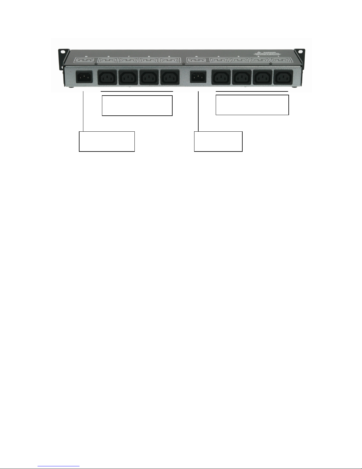
The back panel of the ePowerSwitch 8XM
Power input B
230 VAC – 10 Amp
Power outlets (Group B)
Power outlets 5 – 8
230 VAC max 10 Am
p
Power outlets (Group A)
Power outlets 1 – 4
230 VAC max 10 Am
p
Power input A
230 VAC – 10 Amp

7
1.2 Package list
The following items are included:
1 ePowerSwitch 8XMR2 19"
1 power adapter 12 VDC
2 power cables, 230 V / 10 Amp, length 1.80 Meters
1 RJ45 M/M cable, 2 Meters
1 serial cable SUB-D 9 points M/F, 1.80 Meters
1 quick installation guide
1 CD with User Guide, Quick Start Guide and Windows configuration program

8
2. INSTALLATION
Remark:
Make sure that the ePowerSwitch 8XM is powered off.
Connection instructions
1. Use a shielded RJ45 network cable to connect your ePowerSwitch 8XM to the network.
2. Use appropriated three-wire power cords (two poles plus ground) to connect your electrical devices to
the ePowerSwitch 8XM unit.
3. Plug the 2 power cables into 2 grounded sockets. The power supply LED of group A and of group B
light on to confirm that power is on.
4. You can now configure the ePowerSwitch 8XM by following the indications of the chapter
"Configuration of the ePowerSwitch 8XM".

9
3. CO
N
To use th
e
network a
d
There are
3.1. Co
n
It is the si
configure
compatibl
e
1. Start t
2. Open
ePow
e
3. Open
config
This p
a
versio
n
setting
s
!!! To
Finder
N
FIGU
R
e
ePowerSw
d
ministrator
f
three meth
o
n
figurati
o
mplest and
your ePow
e
e
with those
he Finder.e
x
the File me
n
e
rSwitch 8X
M
the File me
n
ure the net
w
a
ge enable
s
n
of the Firm
w
s
.
achieve th
e
program a
f
R
ATION
itch 8XM on
f
or the para
m
o
ds to config
u
o
n throu
g
fastest conf
i
e
rSwitch 8X
M
of your PC.
x
e program
c
n
u and choo
s
M
connecte
d
n
u and cho
o
w
ork parame
t
s
to define
a
w
are. The H
T
e
highest
s
f
ter the first
your netwo
r
m
eters to us
e
u
re the netw
o
g
h the L
A
i
guration m
e
M
through
y
c
ontained on
s
e SCAN (o
r
d
on your LA
N
o
se CONFI
G
t
ers.
a
ll IP para
m
T
TP protoc
o
s
ecurity lev
e
installatio
n
r
k, you must
e
.
o
rk paramet
e
A
N using
t
e
thod if you
u
y
our local n
e
the CD-RO
M
r
click on the
N
.
G
URE (or cli
c
m
eters of th
e
o
l is enabled
e
l we sug
g
n
.
first configu
r
e
rs of the e
P
t
he Find
e
u
se Windo
w
e
twork even
M
.
first left butt
c
k on the s
e
e
ePowerS
w
and the Fin
d
g
est to dis
a
r
e its networ
P
owerSwitch
e
r progra
m
w
s as operati
if its netw
o
on in the to
o
e
cond left b
u
w
itch 8XM d
e
d
er program
a
ble the co
n
k parameter
s
8XM:
m
ng system.
o
rk paramet
e
o
l bar) to dis
c
u
tton in the
t
e
vice and d
is authorize
d
n
figuration
s
. Ask your
It allows to
e
rs are not
c
over the
t
ool bar) to
isplays the
d
at factory
using the

10
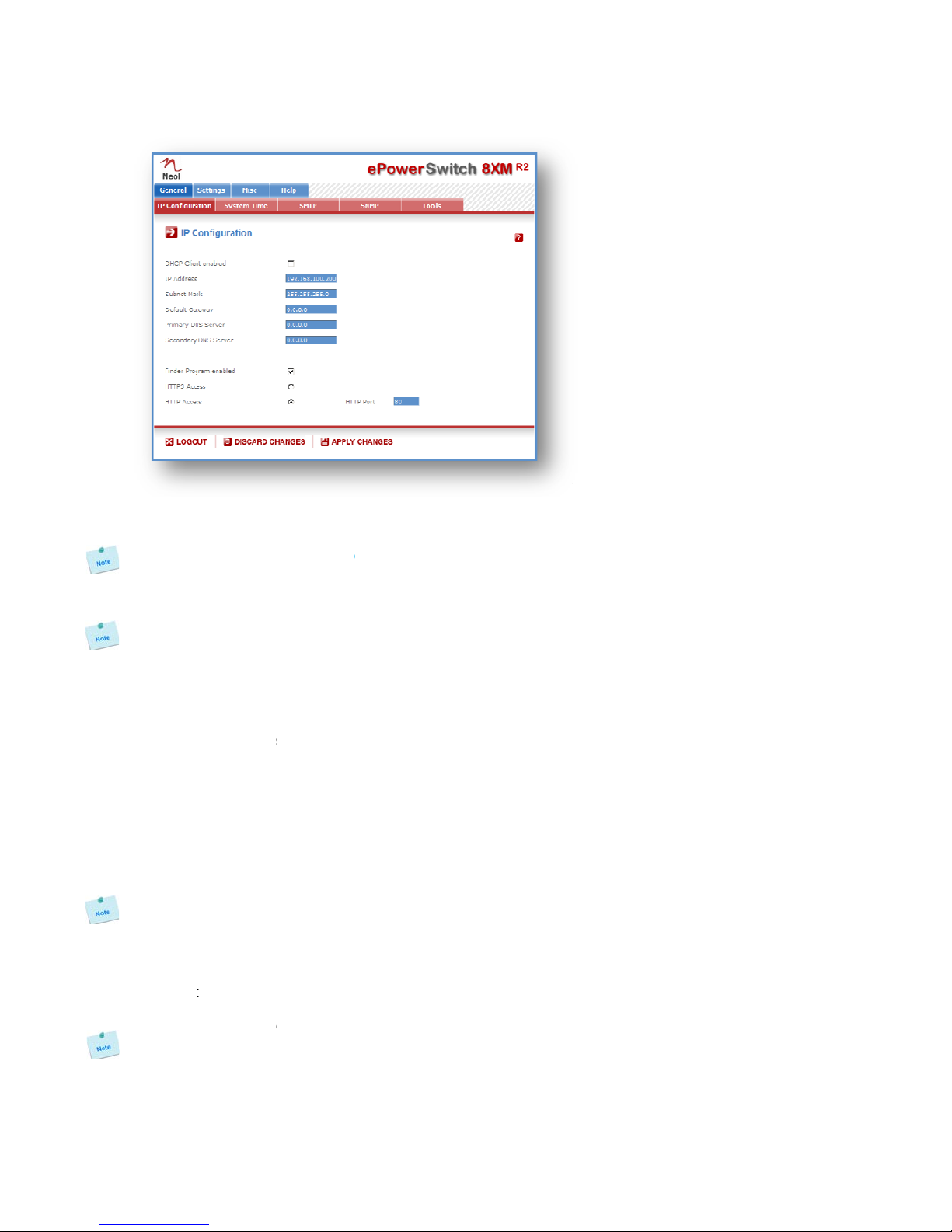
DHCP:
Check this box is you want to obtain the IP address, the subnet mask and the default gateway for your
ePowerSwitch 8XM via DHCP.
Use of DHCP (Dynamic Host Configuration Protocol) requires a DHCP host to be set up on the
network.
IP Address:
IP address of the ePowerSwitch 8XM, default is 192.168.100.200.
Subnet Mask:
Subnet Mask of the ePowerSwitch 8XM, default is 255.255.255.0.
Gateway:
Generally the address of your router, default is blank.
DNS 1:
Primary DNS (Domain Name Server), default is blank.
DNS 2:
Secondary DNS, default is blank.
Version:
Firmware version of the ePowerSwitch 8XM
Finder authorized:
The Network parameters of the ePowerSwitch 8XM can be configured through a Local Area Network
using the provided Finder Program. It is a simple and fast configuration method if you use Windows as
operating system.
!!! The Finder Program is enabled as default value. For security reasons we suggest to disable the
Finder program after the first configuration.
HTTP / HTTPS Access:
These options enable to choose between the standard HTTP and the HTTP over SSL protocol.
HTTPS encrypts and decrypts the page requests and page information between the client browser and
the web server of the ePowerSwitch 8XM using a Secure Socket Layer (SSL). A URL beginning with
HTTPS indicates that the connection is encrypted using SSL. SSL transactions are negotiated by means
of a Key-based encryption algorithm between your browser and the web server of your ePowerSwitch
8XM.
The HTTP protocol is enabled as default value.
HTTP Port Number:
Port number: default is 80 (HTTP).
Standard HTTP port is 80.
Standard HTTPS port is 443.

11
3.2. Co
n
1. Use th
e
PC.
2. Run a
T
3. Config
u
4. On yo
u
5. Press
t
ePowe
3.3. Co
n
During th
e
network s
e
Factory n
e
IP Addres
s
Gateway:
Default fa
c
1. Open
y
http://1
2. Enter t
h
3. The ho
n
figurati
o
e
provided
R
T
erminal pr
o
u
re the appr
o
u
r computer,
t
he “M” on
y
rSwitch 8X
M
n
figurati
o
e
first installa
e
ttings of th
e
e
twork settin
g
s
:192.168.1
255.255.25
5
c
tory protoc
o
y
our Web br
o
92.168.100.
2
h
e administr
a
me page ap
o
n throu
g
R
S232 cabl
e
o
gram such
a
o
priate seria
press <EN
T
y
our keybo
a
M
.
NETWORK
I
Should t
h
Static I
P
Subnet M
a
Gateway
I
Primary
D
Secondar
y
MISCELLA
N
Finder p
r
o
n throu
g
tion, chang
e
e
ePowerSwi
g
s of the eP
o
00.200 - Po
r
5
.0
o
l is HTTP !!
!
o
wser and ty
2
00/sysadm
i
a
tor name a
n
pears, allow
i
g
h an RS
2
e
to connect
a
s Windows
l port @ 9.6
0
T
ER> until th
e
a
rd and foll
o
I
NTERFACE
P
h
is target
P
address
[
a
sk IP add
r
I
P address
D
NS Server
y
DNS Serv
e
N
EOUS:
r
ogram ena
b
g
h the L
A
e
temporarily
tch 8XM.
o
werSwitch
8
r
t: 80
!
pe following
i
n.htm
n
d passwor
d
i
ng you to c
o
2
32 Term
the ePowe
r
HyperTermi
n
0
0, n, 8, 1 a
n
e
menu app
e
o
w the men
u
P
ARAMETERS
:
obtain IP
[
192.168.1
.
r
ess [255.
2
[192.168.
1
IP addres
s
e
r IP addr
e
b
led?[Y]
A
N using
a
the network
8
XM:
IP address:
d
(default for
o
nfigure all s
e
inal con
n
r
Switch 8X
M
n
al.
n
d no flow c
o
e
ars on your
u
to configu
r
:
settings
f
.
250]?
2
55.255.0]
?
1
.2]?
s
[
192.168
.
e
ss [0.0.0
.
a
standa
r
settings of
y
both = adm
i
e
ttings of yo
u
n
ection
M
to an avail
a
o
ntrol.
screen.
r
e the netw
o
f
rom the n
e
?
.
1.2]?
.
0]?
r
d Brows
y
our PC acc
o
i
n)
u
r ePowerS
w
a
ble serial
p
o
rk paramet
e
e
twork?[N]
Configur
e
r
o
rding to the
w
itch 8XM.
p
ort of your
e
rs of your
ation menu
default
3.3.1. G
e
This page
DHCP Cli
e
Check thi
s
ePowerS
w
Use of D
H
network.
IP Addre
s
IP addres
s
If you us
e
keys. Thi
s
times rep
e
Subnet M
Subnet M
a
Default G
a
Generally
Primary
D
Primary D
Seconda
r
Secondar
y
Finder Pr
o
The Netw
o
using the
as operati
n
The Finde
!!!For se
c
HTTP / H
T
This optio
encrypts
a
server of
indicates
t
based en
c
The HTT
P
!!!To achi
e
neral / I
P
enables yo
u
e
nt enabled
s
box is you
w
itch 8XM vi
a
H
CP (Dyna
m
s
s:
s
of the ePo
w
e
the https
s
operatio
n
e
atedly dur
i
ask:
a
sk of the e
P
a
teway:
the address
D
NS Addres
s
NS (Domain
r
y DNS Add
r
y
DNS, defa
u
o
gram ena
b
o
rk paramet
e
provided Fi
n
n
g system.
r Program i
s
c
urity reaso
n
T
TPS Acce
s
n enables t
o
a
nd decrypt
s
the ePower
S
t
hat the con
n
c
ryption alg
o
P
Protocol is
e
eve the hig
h
P
configur
a
u
to define al
:
want to ob
t
a
DHCP. Fa
c
m
ic Host C
o
w
erSwitch 8
X
protocol a
n
n
takes sev
e
i
ng all the
p
P
owerSwitch
of your rout
e
s
:
Name Serv
e
r
ess:
u
lt is blank
b
led:
e
rs of the e
P
n
der Progra
m
s
enabled as
n
s we sugg
e
s
s:
o
choose b
e
s
the page r
e
S
witch 8XM
n
ection is en
c
o
rithm betw
e
nabled as
d
h
est securi
t
a
tion
l the IP para
t
ain the IP
a
c
tory default
o
nfiguratio
n
X
M, default i
s
n
d change t
e
ral minut
e
p
rocess. Du
r
8XM, defau
e
r, default is
e
r), default i
s
P
owerSwitch
m
. It is a ver
y
default valu
e
e
st to disab
e
tween the
s
e
quests and
using a S
e
c
rypted usin
g
een your b
r
d
efault value
t
y level we
s
meters of th
e
a
ddress, the
setting for t
h
n
Protocol)
s
192.168.1
0
he IP addr
e
e
s and the
L
r
ing all this
lt is 255.255
blank.
s
blank
8XM can al
s
y
simple an
d
e
.
le the Find
e
s
tandard H
T
page infor
m
e
cure Sock
e
g
SSL. SSL
r
owser and
.
s
uggest to
c
e
ePowerS
w
subnet mas
h
is option is
d
requires a
0
0.200.
e
ss, the sy
s
L
ED marke
d
time, you c
a
.255.0.
s
o be config
d
fast config
u
e
r program
a
T
TP and the
m
ation betw
e
e
t Layer (S
S
transactions
the web s
e
c
hoose the
H
w
itch 8XM.
k and the d
e
d
isabled.
DHCP hos
t
s
tem needs
d
"Status"
a
nnot login
.
ured throug
h
u
ration meth
a
fter the fir
s
HTTP over
e
en the clie
n
S
L). A URL
are negotia
t
e
rver of yo
u
H
TTPS prot
o
e
fault gatew
t
to be set
to comput
e
on the cas
.
h
a Local Ar
e
od if you us
s
t configur
a
SSL proto
c
n
t browser a
n
beginning
w
t
ed by mea
n
u
r ePowerS
w
o
col.
12
ay for your
up on the
e
new SSL
e blinks 3
e
a Network
e Windows
tion.
c
ol. HTTPS
n
d the web
w
ith HTTPS
n
s of a Key-
w
itch 8XM.

13
HTTP Port:
Port number: default is 80 (HTTP).
Standard HTTP port is 80.
Standard HTTPS port is 443.
LOGOUT:
Click "Logout" at the bottom of the page to exit the session without saving changes.
DISCARD CHANGES:
Click "Discard Changes" at the bottom of the page to discard all the changes you have made on this page.
APPLY CHANGES:
Click "Apply Changes" at the bottom of the page to save changes.
3.3.2. G
e
The syste
m
SNMP tra
p
browser ti
timeserve
r
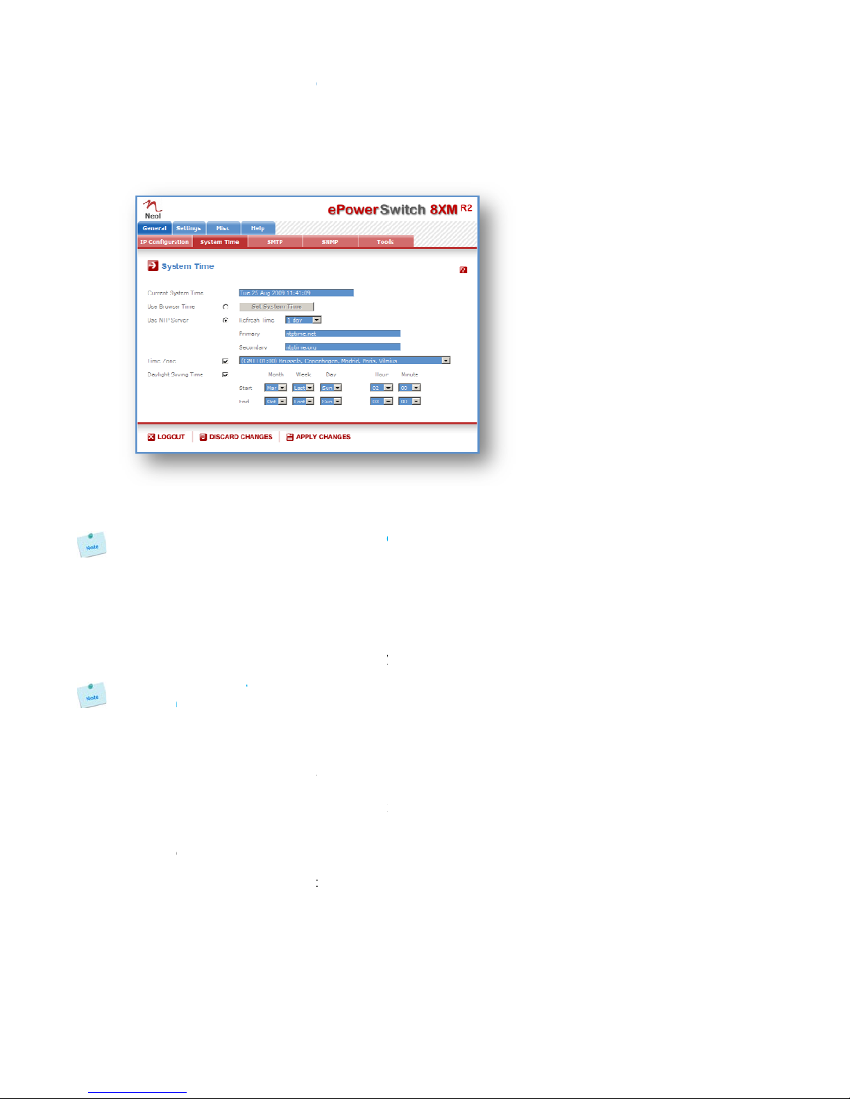
Current
S
This field
s
As the sy
compare
d
Use Bro
w
If you wa
n
on the "S
e
Use NTP
S
If you wa
n
and enter
timeserve
r
only if the
Y
ou can
e
configur
a
NTP uses
Time Zon
e
Set the ti
m
Without s
e
are synch
r
Daylight
S
If you wan
LOGOUT
:
Click "Log
o
DISCARD
Click "Dis
c
APPLY C
H
Click "Ap
p
e
neral / S
y
m
time of th
e
p
s, Syslog i
n
me of the
c
r
s.
S
ystem Tim
e
s
hows the c
u
stem time i
s
d
to the exa
c
w
ser Time:
n
t to set the
e
t System Ti
m
S
erver:
n
t to set the
the IP addr
e
r
can be sp
e
primary tim
e
e
nter eithe
r
a
tion page)
o
port 123/U
D
e
:
m
e zone co
r
e
tting this, th
r
onizing with
S
aving Tim
e
t to set Dayl
:
o
ut" at the b
o
CHANGES
c
ard Chang
e
H
ANGES:
p
ly Changes
"
y
stem tim
e
e
ePowerSw
n
formation,
e
c
onnected c
e
:
u
rrent syste
m
s
displayed
c
t hour. Th
e
system time
m
e" button.
system tim
e
e
ss of the ti
m
e
cified in th
e
e
server is no
t
r
the hostn
a
o
r the IP ad
d
D
P.
r
responding
e system cl
o
an NTP ser
v
e
:
ight Saving
d
o
ttom of the
:
e
s" at the bo
t
"
at the botto
e
itch 8XM is
u
e
-mails and i
omputer or
m
time of the
through th
e
e
system ti
m
using the c
u
e
using an N
m
eserver yo
u
e
"Secondar
y
t
available.
a
me (in that
d
ress of an
to your loc
a
o
ck will sho
w
v
er.
d
ates, chec
k
page to exit
t
tom of the p
a
m of the pa
g
u
sed for syn
c
nternal logs
.
can be aut
o
ePowerSwi
t
e
browser,
a
m
e is nevert
h
u
rrent Brow
s
TP timeser
v
u
wish to us
e
y
" field. Th
e
case you
m
NTP server
.
a
tion. The s
y
w
UTC/GMT
k
this box an
d
the session
a
ge to disca
r
g
e to save c
h
c
hronizing s
c
.
The syste
m
o
matically s
y
t
ch 8XM.
a
small diff
e
h
eless corr
e
s
er time of y
v
er, select th
e
in the "Pri
m
e
secondary
m
ust have
s
.
y
stem clock
time. Settin
g
d
specify the
without savi
r
d all the ch
a
h
anges.
c
heduling a
c
m
time can b
e
y
nchronized
e
rence (1 t
o
e
ct.
our PC, sel
e
is option, c
h
m
ary" field. T
h
timeserver
i
s
pecified a
will subseq
u
g
a time zon
e
date you w
a
ng changes.
a
nges you h
a
c
tions and to
e
set manu
a
with one
o
o
2 sec) can
e
ct this opti
o
h
oose a refr
e
h
e address
o
i
s optional
a
DNS serve
r
u
ently show
e
is only rel
e
a
nt to use.
a
ve made o
n
14
timestamp
a
lly with the
o
r two NTP
appear as
o
n and click
e
sh interval
o
f a second
a
nd is used
r
on the IP
local time.
e
vant if you
n
this page.

15
3.3.3. G
e
You can
s
triggered
b
To send
e
following
SMTP en
a
Check thi
s
SMTP Se
r
In this fiel
d
Y
ou can
e
configur
a
NTP uses
SMTP Po
r
In this fiel
d
From (e-
m
In this fiel
d
The name
a valid ad
d
Example:
yourname
@
LOGOUT
:
Click "Log
o
DISCARD
Click "Dis
c
APPLY C
H
Click "Ap
p
e
neral / S
M
s
etup the e
P
b
y the rules
d
e
-mails, yo
u
parameter
s
a
bled:
s
box if you
w
r
ver Addres
d
, enter the
a
e
nter eithe
r
a
tion page)
o
port 123/U
D
r
t:
d
, enter the
P
m
ail Addres
s
d
, enter the
e
can be fro
m
d
ress (gene
r
@
yourmails
e
:
o
ut" at the b
o
CHANGES
c
ard Chang
e
H
ANGES:
p
ly Changes
"
M
TP
P
owerSwitc
h
d
efined by t
h
u
will need
s
:
w
ant the eP
o
s:
a
ddress of t
h
r
the hostn
a
o
r the IP ad
d
D
P.
P
ort Number
s
):
e
-mail addre
s
m
1 to 64 ch
a
r
ally servers
e
rver.net
o
ttom of the
:
e
s" at the bo
t
"
at the botto
h
*8XM to s
e
h
e administr
a
a SMTP se
r
o
werSwitch
8
h
e e-mail ser
v
a
me (in that
d
ress of an
you want to
s
s that ePo
w
a
racters lon
g
reject mess
a
page to exit
t
tom of the p
a
m of the pa
g
e
nd the log
s
a
tor.
r
ver on the
8
XM to be a
b
v
er you wan
t
case you
m
NTP server
.
use, defaul
t
w
erSwitch 8
X
g
, and can c
o
a
ges that do
n
the session
a
ge to disca
r
g
e to save c
h
s
to an em
a
network a
n
b
le to send e
-
t
to use.
m
ust have
s
.
t
and usual
p
X
M message
s
o
ntain alpha
n
't have a v
a
without savi
r
d all the ch
a
h
anges.
a
il account
a
n
d you will
h
-
mails.
s
pecified a
p
ort is 25.
s
will appea
r
numeric ch
a
a
lid from add
r
ng changes.
a
nges you h
a
a
nd report
a
h
ave to co
n
DNS serve
r
r
to come fr
o
a
racters. Thi
s
r
ess).
a
ve made o
n
a
ll activities
n
figure the
r
on the IP
o
m.
s
should be
n
this page.

3.3.4. G
e
The ePo
w
enables y
o
ePowerS
w
all sensor
s
and all gr
o
from the
G
SNMP en
a
Check thi
s
Contact:
In this fie
character
s
Name:
In this fiel
d
long, and
c
Location:
In this fie
l
character
s
Read Co
m
In this fiel
d
character
s
Write Co
m
Check thi
s
field, ente
r
long, and
c
Trap Co
m
Check thi
communit
y
be from 1
Trap Des
t
Check thi
s
Trap Des
t
Check thi
s
LOGOUT
:
Click "Log
o
DISCARD
Click "Dis
c
APPLY C
H
Click "Ap
p
e
neral / S
N
w
erSwitch 8
X
o
u to manag
w
itch 8XM M
s
(temperat
u
o
ups of pow
e
G
eneral / To
o
a
bled:
s
box if you
w
ld, enter th
e
s
long, and c
a
d
, enter the
n
c
an contain
a
l
d, enter th
e
s
long, and c
a
m
munity:
d
, enter the
n
s
long, and c
a
m
munity:
s
box if you
w
r
the name
y
c
an contain
a
m
munity:
s box if y
o
y
. In the foll
o
to 64 chara
c
t
ination 1:
s
box and en
t
ination 2:
s
box and en
:
o
ut" at the b
o
CHANGES
c
ard Chang
e
H
ANGES:
p
ly Changes
"
N
MP
X
M provides
e the ePow
e
IB file enabl
e
u
re, humidit
y
e
r outlets. T
h
o
ls Page.
w
ant to enab
e
name yo
u
a
n contain a
n
ame you w
a
a
lphanumeri
e
name you
a
n contain a
n
ame you w
a
a
n contain a
w
ant to be a
y
ou want to
g
a
lphanumeri
o
u want to
c
o
wing field,
e
c
ters long, a
n
ter the prim
a
ter the seco
n
o
ttom of the
:
e
s" at the bo
t
"
at the botto
a built-in S
N
e
rSwitch 8X
M
e
s to remot
e
y
, ambient li
g
h
e MIB file i
s
le the SNM
P
u
want to gi
v
lphanumeri
c
a
nt to give t
o
c character
s
want to gi
v
lphanumeri
c
a
nt to give t
o
lphanumeri
c
ble to contr
o
g
ive to the
W
c character
s
c
onfigure t
h
e
nter the na
m
n
d can cont
a
a
ry SNMP S
e
n
dary SNM
P
page to exit
t
tom of the p
a
m of the pa
g
N
MP (Simpl
e
M
through S
N
e
ly read out
t
g
ht). It also
e
s
stored on t
h
P
protocol.
v
e to the
C
c
characters.
o
the Name
s
. Default na
m
v
e to the L
o
c
characters.
o
the Read
C
c
characters.
o
l the power
W
rite Comm
u
s
. Default na
m
h
e ePowerS
w
m
e you wan
t
a
in alphanu
m
e
rver addre
s
P
Server add
the session
a
ge to disca
r
g
e to save c
h
e
Network
M
N
MP-based
n
t
he status o
f
e
nables to
c
h
e ePowerS
w
C
ontact field
.
Default na
m
field. The n
a
m
e is "name
o
cation field
Default na
m
C
ommunity f
i
Default na
m
outlets thro
u
u
nity. The n
a
m
e is "privat
e
w
itch 8XM
t
to give to t
h
m
eric charact
e
s
s the traps
w
ress the tra
p
without savi
r
d all the ch
a
h
anges.
M
anagement
n
etwork ma
n
f
all power o
u
c
ontrol indivi
d
w
itch 8XM
a
.
The name
m
e is "contac
a
me can be
f
".
. The nam
e
m
e is "locatio
i
eld. The na
m
m
e is "public"
u
gh a MIB b
r
a
me can be
f
e
".
SNMP age
n
h
e Trap Co
m
e
rs. Default
n
w
ill be sent t
o
p
s will be se
n
ng changes.
a
nges you h
a
Protocol) a
g
n
agement sy
s
u
tlets and th
d
ually all po
w
a
nd can be
d
can be fr
o
t".
f
rom 1 to 64
e
can be fr
o
n".
m
e can be f
r
.
r
owser. In t
h
f
rom 1 to 64
n
t to send
m
munity. Th
e
n
ame is "tra
p
o
.
n
t to.
a
ve made o
n
16
g
ent, which
s
tems. The
e values of
w
er outlets
d
ownloaded
o
m 1 to 64
characters
o
m 1 to 64
r
om 1 to 64
h
e following
characters
traps to a
e
name can
p
".
n
this page.
17
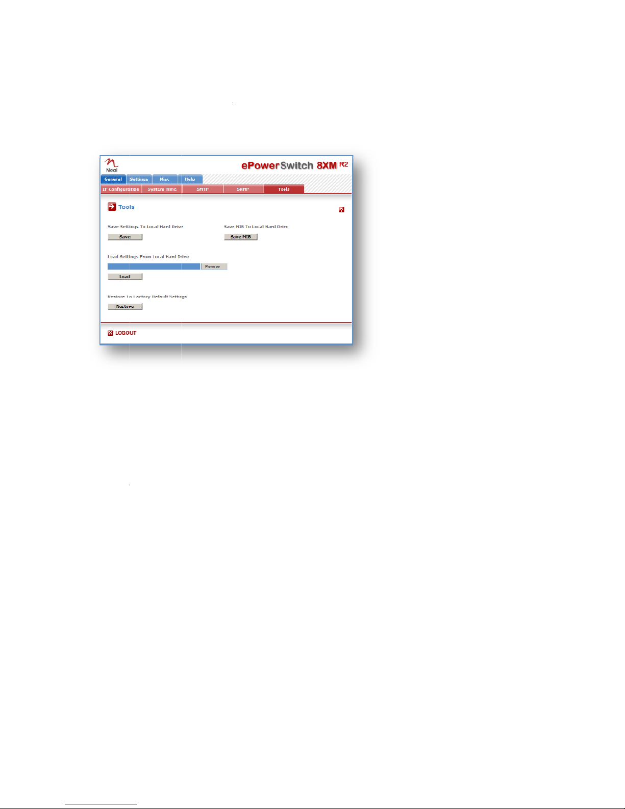
3.3.5. G
e
This page
- downloa
d
- upload a
- restore t
h
- downloa
d
Save:
Click this
b
Load:
Click this
b
Restore:
Click this
b
Save MIB
Click this
b
LOGOUT
:
Click "Log
o
e
neral / T
o
enables yo
u
d
and save t
h
n existing c
o
h
e factory s
e
d
the ePowe
b
utton to sa
v
b
utton and s
e
b
utton if you
:
b
utton if you
:
o
ut" at the b
o
o
ols
u
to:
h
e current s
e
o
nfiguration
f
e
ttings,
rSwitch 8X
M
v
e the curre
n
e
lect a setti
n
want to rest
o
want to do
w
o
ttom of the
e
ttings of yo
u
f
ile to your e
P
M
MIB file on
n
t system se
t
n
gs file you
w
o
re the fact
o
w
nload the e
P
page to exit
u
r ePowerS
w
P
owerSwitc
h
your PC.
t
tings onto y
o
w
ant to down
o
ry default s
e
P
owerSwitch
the session
w
itch 8XM o
n
h
8XM,
o
ur local har
d
load to the
e
e
ttings.
8XM MIB fil
without savi
n
your PC,
d
drive.
e
PowerSwit
c
e onto your
ng changes.
c
h 8XM.
local hard d
r
r
ive.
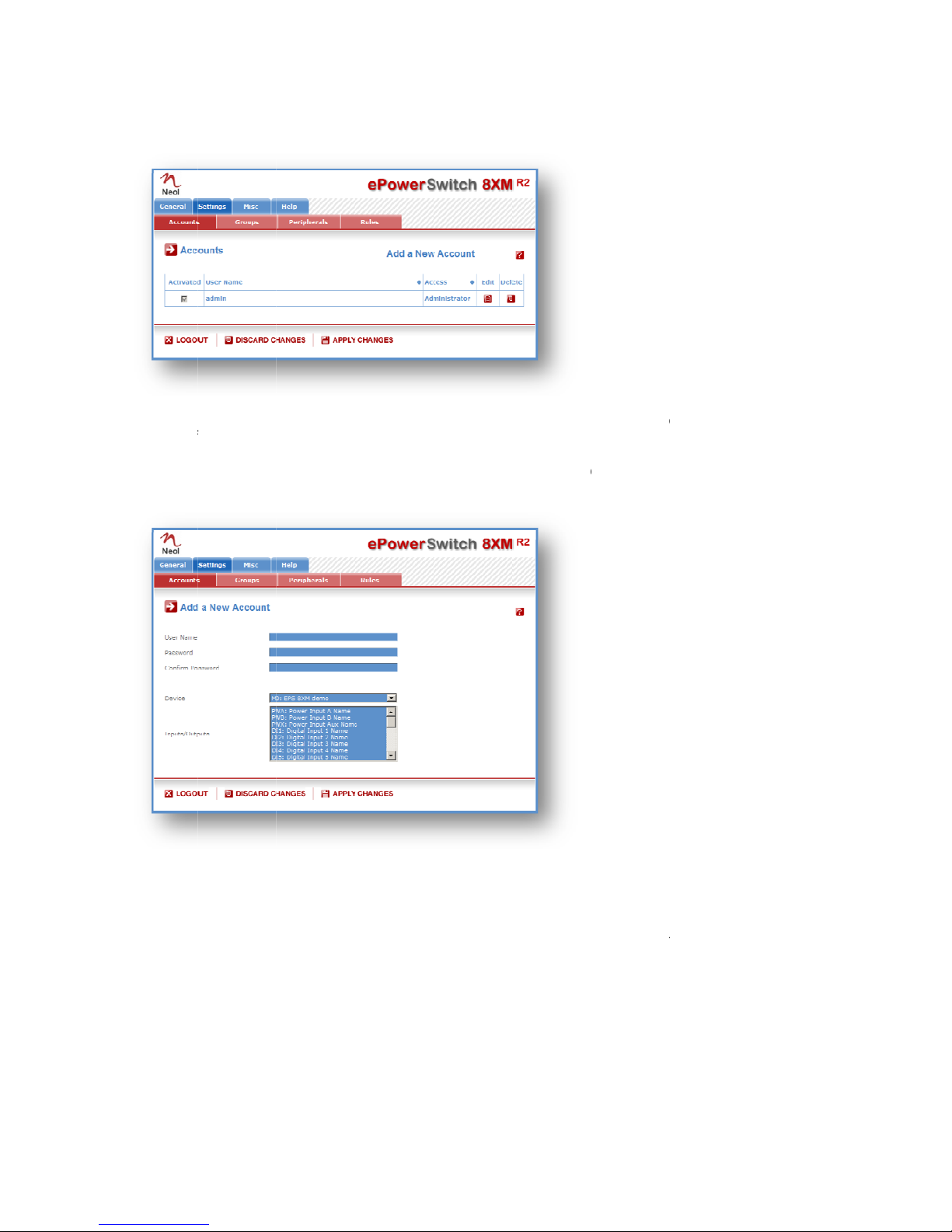
3.3.6. S
e
This page
- To activ
a
- To modi
f
- To delet
e
- To creat
e
A
new p
a
User Na
m
In this fiel
d
and can c
o
Passwor
d
In this fiel
d
long, and
c
Confirm
P
In this fiel
d
e
ttings /
A
is used to c
r
a
te or deacti
v
f
y an accoun
e
an existing
e
an accoun
t
a
ge appear
s
m
e:
d
, enter the
n
o
ntain alpha
n
d
:
d
, enter the
p
c
an contain
a
P
assword:
d
, enter the
p
A
ccounts
r
eate, activa
t
v
ate an acco
t, click on "
E
account, cli
c
t
, click on "A
d
s
, allowing y
o
n
ame you w
a
n
umeric cha
p
assword yo
u
a
lphanumeri
p
assword ag
t
e, deactivat
e
unt, check
o
E
dit" next to t
c
k on "Delet
e
d
d a New A
c
o
u to set all t
a
nt to give to
racters.
u
want to gi
v
c character
s
ain.
e
, modify an
o
r uncheck t
h
he correspo
n
e
" next to th
e
c
count" on t
h
he paramet
e
the user. T
h
v
e to the use
s
.
d delete up
t
h
e correspon
n
ding accou
n
e
correspon
d
h
e right side
o
e
rs of the ac
c
h
e name ca
n
r. The pass
w
t
o 255 acco
u
ding checkb
o
n
t.
d
ing account
o
f the page.
c
ount.
n
be from 1 t
o
w
ord can be
f
u
nts.
ox.
.
o
32 charact
e
f
rom 4 to 32
18
e
rs long,
characters

19
Groups:
This field is used to add or remove groups to the current account.
To add Groups to the current account, press the Ctrl key and click on the displayed Groups. The selected
Groups are marked dark blue and their IDs are listed at the right side of the Groups field.
This field appears only if you have already created at least one group (Settings/Groups Tab).
Device:
In this drop-down list, choose a device from which you want to add Inputs or Outputs to the current
account.
Inputs/Outputs:
This field is used to add/remove Inputs or Outputs to/from the current account.
To add Inputs or Outputs to the current account, press the Ctrl key and click on the Inputs/Outputs of the
device selected in the previous field. The selected Inputs/Outputs are marked dark blue and their IDs are
listed at the right side of the Input/Output field.
The ePowerSwitch 8XM supports number of peripherals which are clearly identified by specific ID Codes.
LOGOUT:
Click "Logout" at the bottom of the page to exit the session without saving changes.
DISCARD CHANGES:
Click "Discard Changes" at the bottom of the page to discard all the changes you have made on this page.
APPLY CHANGES:
Click "Apply Changes" at the bottom of the page to save changes.
Table of contents
Other Neol Switch manuals


