Neptronic SKH4 Manual

SKH4-N-ESL-231208
SKH4 High-Pressure Atomizer
Installation Instructions and User Manual
Read and save this manual
4011008

SKH4 High-Pressure Atomizer
Installation Instructions and User Manual
www.neptronic.com
Page | i
Foreword
Neptronic Company Overview
Founded in 1976, Neptronic is a private corporation that designs, manufactures and distributes products for the HVAC
industry. Our product line includes intelligent controllers, electronic actuators, actuated valves, humidifiers and electric
heaters.
Our products are designed and manufactured by over 250 dedicated employees in our 7,500 m2(80,000 ft2) state-of-the-art
facility located in Montreal, Canada. Our entire manufacturing chain is under one roof from software and hardware
development to SMT circuit board assembly, to sheet metal fabrication, to product testing ensuring that our products are
engineered to last using a vertical integration model.
We currently hold several national and international patents, and with our continued commitment to research and
development, we provide innovative products and technologies for the ever-evolving challenges of the HVAC industry.
Exporting over 75% of our sales, we have an exclusive distribution network around the globe that provides comprehensive
solutions to our worldwide customers.
About the Manual
These installation and operation instructions have been developed to facilitate the installation of the SKH4 High-Pressure
Atomizer humidifier.
•The strict application of these instructions ensures conformity of your installation and operation as per the
manufacturer's recommendations.
•The application of these instructions is one of the conditions for the application of the warranty.
•The application of these instructions does not ensure, at any time, conformity to procedures, regulation or local
codes, regarding electric connections and installation to local water supply.
This product has been declared to conform to the applicable Canadian and American safety standards and directives and
bear the ETL (c) & (us) mark. The Certificate of Conformity for ETL is available, upon request with the manufacturer.
Copyright Information
Copyright ©2023 by Neptronic.
All rights reserved. This document cannot be reproduced wholly or partially by any means, whether electronic, mechanical,
photocopy, recording or other, without prior written authorization of Neptronic.

SKH4 High-Pressure Atomizer
Installation Instructions and User Manual
www.neptronic.com
Page | ii
Health and Safety Instructions
General
This manual has been written to ensure correct, safe and sustainable operation of the SKH4 High-Pressure Atomiser and
is intended for use by engineers and technical personnel trained by or their official agents. This manual must be read
thoroughly before specifying, designing, installing or operating a SKH4 High-Pressure Atomizer. Please retain for reference
and contact Neptronic should you have any questions.
The triangular symbol with the word WARNING: is used to designate danger of severe or lethal consequence.
The circular symbol with the word CAUTION: is used to designate danger of injury, or to warn of the hazardous
operating condition, or other relevant information.
Electrical Warning Message
WARNING:
Risk of electric shock. Do not access. Disconnect SKH4 High-Pressure Atomizer before opening the electrical access door.
All work concerned with electrical installation MUST only be performed by skilled and qualified technical personnel (such as
an electrician or a technician with appropriate training). The customer is always responsible for ensuring the suitability of
the technical personnel.
Please observe the local regulations concerning the provision of electrical installations.
Health & Safety
Installation, maintenance, repair work or de-commissioning should only be carried out by appropriately qualified technical
personnel. Any risks or hazards relating to the system, including during installation and maintenance, should be identified
by a qualified Health & Safety representative who shall be responsible for introducing effective control measures, as
necessary. The customer is responsible for ensuring that the installation of the equipment complies with all local regulations.
CAUTION: Maintenance personnel must be trained by Neptronic or their official agent, and it is the customer’s
responsibility to ensure their suitability. Failure to use qualified personnel may lead to a hazardous operating
condition.
WARNING: Danger of Electrocution! Danger of contact with live parts when the unit is open. Always isolate all
water and electrical supplies to the system before commencing any maintenance or repair. Isolate power and
water immediately if there are any signs of water leaking from the unit.

SKH4 High-Pressure Atomizer
Installation Instructions and User Manual
www.neptronic.com
Page | iii
Hygiene
IMPORTANT:
Refer to local Health and Safety regulation and codes on the control of Legionellosis in water systems. In the absence of
such, ASHREA guideline 12-2023 does provide recommendations. If not adequately monitored and maintained, water
systems can support the growth of microorganisms including the bacterium that causes Legionnaires’ disease.
The SKH4 has been designed to reduce the potential risk of legionellosis growth. Users also share the responsibility for
reducing the risk of legionellosis; users are required to:
•Conduct a risk assessment of the complete water system.
•Implement proper control of the water system.
•Connect the SKH4 to a clean water supply main or higher quality water (such as RO).
•Avoid stagnant water.
•Avoid turning off the system without properly draining all conduit. Automatic drains are scheduled in the unit to
avoid the stagnant water.
•Avoid water temperatures that increase the risk of Legionella growth. (77°F to 113°F, 25°C to 45°C)
•Clean and disinfect the system regularly, at least once a year.
WARNING: Risk of Legionnaires’ disease, which can be fatal. Install and operate the SKH4 High-Pressure
Atomizer as per the instructions given in this Installation Instructions and User Manual.
WARNING: If the SKH4 High-Pressure Atomizer is turned off for prolonged periods (more than 24 hours),
ensure that any piping supplying the unit is drained, unless they supply other systems which ensure a regular
renewal of water in the system. Failure to do so may result in stagnation of the water and contamination that
might cause Legionnaires' disease, which can be fatal.
It is the responsibility of the person on whom the statutory responsibility falls to determine all control and preventative
measures outlined in this manual.
Correct Use
Neptronic systems and products are designed only for humidification and cooling use. Any other application is not
considered appropriate for the intended purpose. The manufacturer cannot be made liable for any damage resulting from
incorrect use.
Important Start-Up Information
Before turning on and operating the SKH4 High-Pressure Atomizer:
•Read all instructions and installation procedures outlined in this manual. Ensure that the operation of the system is
properly understood before commencing the start-up procedure.
•Ensure that all wiring is properly installed and that all connections have been made correctly, including the network
communication cable between the pump station and the RVP(s).
•Verify all piping before starting up the system. As each zone may have a different capacity and the system has been
configured as such, connecting the wrong RVP output to a zone may lead to erratic operation.
General Warranty
This product is subject to the terms and conditions described at www.neptronic.com/sales-conditions.aspx.

SKH4 High-Pressure Atomizer
Installation Instructions and User Manual
www.neptronic.com
Page | iv
Handling and Packaging
Lifting or Handling MUST be carried out by trained and qualified personnel. Ensure that the lifting
operation has been properly planned, assessed for risk and that the equipment is checked by a
qualified Health & Safety representative, and effective control measures are in place.
It is the customer’s responsibility to ensure that the operators are trained in handling heavy goods and
to enforce the relevant lifting regulations.
The SKH4 High-Pressure Atomizer MUST always be handled and lifted with care and should remain
in its original packaging for as long as possible before installation.
The SKH4 High-Pressure Atomizer package may be carried using a forklift from the underside. Caution
should be exercised to ensure balanced load before lifting.
Inspection
Upon receipt, and once packaging material is removed, carry out an inspection to ensure that no damage occurred during
transit. Report any damage immediately to your Neptronic representative.
Unpacking
The SKH4 pump station is delivered in a crate. All other optional products, such as the distributors or the remote valve panel
are delivered separately in carton.

SKH4 High-Pressure Atomizer
Installation Instructions and User Manual
www.neptronic.com
Page | v
Table of Contents
Handling and Packaging ....................................................................................................................................................iv
Overview.................................................................................................................................................................................................... 7
Benefits................................................................................................................................................................................7
Features ..............................................................................................................................................................................7
SKH4 System............................................................................................................................................................................................ 8
Principle of Operation..........................................................................................................................................................8
SKH4 Pump Station................................................................................................................................................................................... 9
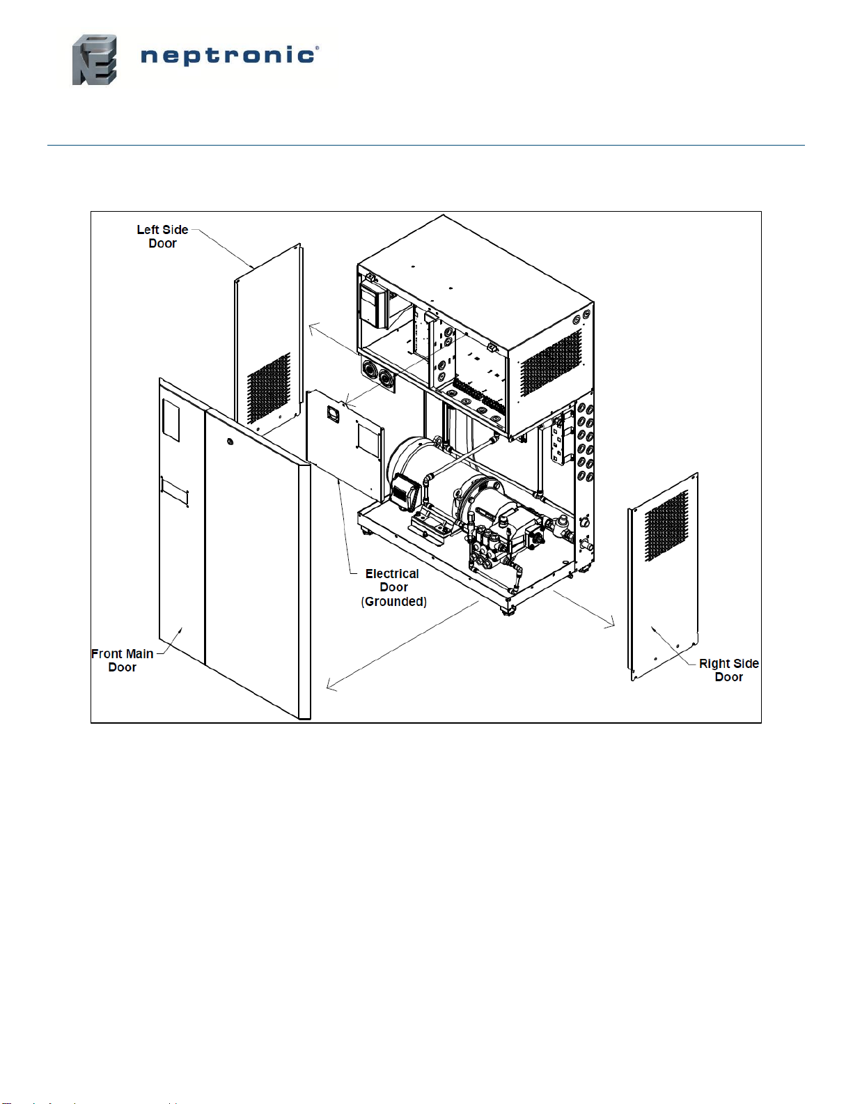
Visual Overview ..................................................................................................................................................................9
Pump Unit Nomenclature................................................................................................................................................. 11
Capacities and Power Consumption of the Pump Unit (Brass) ....................................................................................... 12
Capacities and Power Consumption of the Pump Unit (SS)............................................................................................ 13
Dimensions and Weight ................................................................................................................................................... 14
Fan-Assisted Distributors......................................................................................................................................................................... 15
Fan-Assisted Distributors Nomenclature.......................................................................................................................... 15
Capacities and Power of the Fan-Assisted Distributors................................................................................................... 15
Fan-Assisted Distributors Dimensions and Weight.......................................................................................................... 16
In-Duct Distribution Rack......................................................................................................................................................................... 17
Basic Installation Overview...................................................................................................................................................................... 18
Pump Unit Installation.............................................................................................................................................................................. 19
Step 1 –SKH4 Pump Station Installation......................................................................................................................... 19
General Recommendations.................................................................................................................................................. 19
Step 2 –Water Connections for the SKH4 Pump Station................................................................................................ 21
Step 3 –Power Supply Connections................................................................................................................................ 23
Power Supply Connections on SKH4 Pump Station............................................................................................................ 23
Power Supply Knockout Holes Location on SKH4 Pump Station........................................................................................ 24
Step 4 –Electrical Control Connections........................................................................................................................... 25
Safety Contact Connections for Pump Unit.......................................................................................................................... 25
Safety Contact Connections Single Zone Without TRUB .................................................................................................... 25
Safety Contact Connections per Zone from TRUB .............................................................................................................. 25
Network Communication ...................................................................................................................................................... 26
Step 5 –Pump Controller Installation and Configuration................................................................................................. 27
Idle Screen .............................................................................................................................................................................................. 28
Menu Access.................................................................................................................................................................... 28
Configuration parameters..................................................................................................................................................... 29
Control function .................................................................................................................................................................... 29
Control Profile Selection....................................................................................................................................................... 29
Single Zone Operation ......................................................................................................................................................... 29
Multi-Zones Operation.......................................................................................................................................................... 30
Menu - General [Level 1 - No password required]............................................................................................................... 31
Menu - User Settings [Level 2 - Requires level 2 (or higher) password in order to access]................................................ 34
Menu - Service [Level 3 - Requires level 3 (or higher) password in order to access].......................................................... 36
Menu - Installation [Level 4 - Requires level 4 (or higher) password in order to access] .................................................... 37
Menu - Integration [Level 5 - Requires level 5 password in order to access] ...................................................................... 41
List of Alarms and Warnings ............................................................................................................................................ 44
Distribution Installation............................................................................................................................................................................. 45
Spraying in Space (Standard) .............................................................................................................................................. 45
Spraying in Space with Fan-Assisted Distributors ............................................................................................................... 47
Spraying in Duct................................................................................................................................................................... 50

SKH4 High-Pressure Atomizer
Installation Instructions and User Manual
www.neptronic.com
Page | vi
Optional –Remote Valve Panel (RVP).................................................................................................................................................... 51
RVP Dimensions .............................................................................................................................................................. 51
Location................................................................................................................................................................................ 52
Positioning............................................................................................................................................................................ 52
Wall Mounting....................................................................................................................................................................... 52
Start-Up Procedure.................................................................................................................................................................................. 53
Initial Verification .............................................................................................................................................................. 53
Diagnostic mode............................................................................................................................................................... 54
Servicing and Maintenance ..................................................................................................................................................................... 55
Preventative Maintenance................................................................................................................................................ 55
Preventive Maintenance (continued)................................................................................................................................ 56
Nozzle Cleaning ............................................................................................................................................................... 57
De-scaling the Droplet Separator..................................................................................................................................... 58

SKH4 High-Pressure Atomizer
Installation Instructions and User Manual
www.neptronic.com
Page | 7
Overview
The SKH4 High-Pressure Atomizer uses water through a high-pressure system to produce a fine mist with a droplet size of
less than 20µm. The ambient air absorbs the fine mist, and the SKH4 adapts to seasonal changes to provide direct
evaporative cooling in summer and humidification in winter. Additionally, the SKH4 provides BACnet MS/TP communication,
multi-zone operation (up to 4 zones) and remote connection to the entire system from any zone.
Benefits
•Very low energy consumption
•Free cooling (up to 21.5°F [12°C])
•Hygienic operation
•Environmentally friendly
•Low pressure drop in ventilation conduit
Features
The following are the features of the SKH4 High-Pressure Atomizer:
•High pressure pump with recirculation valve integrated.
•Full stainless steel distribution valves and fittings.
•Corrosion resistant distribution network made of stainless steel pipe or nylon tube.
•BACnet communication (optional).
•User-friendly, menu-driven LCD (128 x 64).
•Real-time clock and SD card or USB key for schedule, trending, and history log.
•Firmware upgrade using an SD card or USB key.

SKH4 High-Pressure Atomizer
Installation Instructions and User Manual
www.neptronic.com
Page | 8
SKH4 System
Principle of Operation
The SKH4 High-Pressure Atomizer is a system for humidifying and cooling with a fine mist of water droplets. The pump unit
pressurizes the high-quality water until it reaches a pressure of 1000psi (69bar), then distributes it throughout a network of
stainless steel pipes or nylon flexible conduits, which then distributes the pressurized water as a fine mist. These water
particles measure less than 20µm. This mist is then easily absorbed into the air, providing humidification, and cooling,
through the adiabatic evaporation process.
The SKH4 Pump Unit is equipped with a pump and a motor that can use an optional VFD in order to control the pump speed.
The regulation of the outlet pressure is assured mechanically by the pump, in order to maintain a consistent and reliable
outlet pressure, regardless of the configuration of stages open.
The unit is equipped with two analog manometers place in the front, one for the low pressure and one for the high-pressure
outlet. There are also digital manometers so that the controller can monitor those pressures. The low pressure controls the
input of water to the pump in order to protect the pump unit from running dry. The high-pressure sensor monitors the output
of the pump, in order to assure consistent mist generation and detect leakage.
In case of unexpected shutdown and failure of valve that could create a water hammer coming back to the pump, a pressure
relief is placed in the recirculation loop. The relief valve prevents damage to the inlet of the pump and the low-pressure
components.
The distribution of high-pressure water is assured in the pump unit, or optionally from a remote valve panel, with an array of
configurable valves. Each pair of valves (one for the input and one for the drain) is assigned at the installation to a capacity
in mass per hour and to a control signal. The unit is able to receive up to 4 control signals in order to cover 4 different zones,
which can also be split up into 6 stages in total.
The control signals are displayed either by using a thermostat in each zone that is connected to the unit or by connecting
through a BMS with a demand directly to the unit. The BMS can be connected via BACnet or Modbus protocols.
The distribution of mist is accomplished by using anti-drip stainless steel nozzles which are designed to create a cone of
mist to shoot the water droplets directly into the air. The nozzles are either installed directly in the space or in an AHU.
In-space distribution requires installing distribution piping (stainless steel or nylon flexible conduit), with a fitting for each
nozzle. Clearances are important between nozzles and any obstacle in the area, such as trusses, columns and/or tall
equipment. See the hydraulic and distribution design guide for more details.
In-space distribution can be facilitated with optional fan-assisted distributors. Those distributors allow reduced absorption
distances and improve the coverage of the distribution network.

SKH4 High-Pressure Atomizer
Installation Instructions and User Manual
www.neptronic.com
Page | 9
SKH4 Pump Station
Visual Overview
Illustration 1 - SKH4 Enclosure

SKH4 High-Pressure Atomizer
Installation Instructions and User Manual
www.neptronic.com
Page | 10
Illustration 2 - Detailed Overview of Components
Illustration 3 - Detailed Overview of Low Pressure Components

SKH4 High-Pressure Atomizer
Installation Instructions and User Manual
www.neptronic.com
Page | 11
Pump Unit Nomenclature
Table 1 - Pump Module Nomenclature
Pump Module Nomenclature
SKH4-ABBBC DD EF
Designation
Notation
Description
A
N: North America - 60Hz
Frequency
BBB
005 to 300
Capacity (lb/h)
C
B (Brass)
Pump Type
S (Stainless)
DD
0 to 6
Number of Inlet Valves (Zero implies valve in the RVP)
0 to 6
Number of Drain Valves (Zero implies valve in the RVP)
E
A: 120 VAC / 1ph
Supply Voltage
B: 208 / 1ph
C: 220-240 VAC / 1ph
D: 208 / 3ph
E: 220-240 VAC / 3ph
G: 480 VAC / 3ph
H: 600 VAC / 3ph
F
[blank] (On/Off)
Motor Control
M (Modulating - Controlled with
VFD)

SKH4 High-Pressure Atomizer
Installation Instructions and User Manual
www.neptronic.com
Page | 12
Capacities and Power Consumption of the Pump Unit (Brass)
Table 2 - Capacities and Power Consumption of the Pump Unit (Brass)
Brass Pump
Model
Max
output
(lb/h)
Min
Output
(lb/h)
MCA (A)
Cabinet
A
B
C
D
E
G
H
120/1
208/1
240/1
208/3
240/3
480/3
600/3
SKH4-N021B
210
52
15.0
8.6
7.5
4.9
4.3
2.1
1.7
S
SKH4-N021B - M
210
20
8.4
4.8
4.2
4.8
4.2
2.1
1.7
S
SKH4-N050B
500
125
22.4
12.9
11.2
7.7
6.6
3.3
2.7
S
SKH4-N050B - M
500
20
13.1
7.6
6.6
7.6
6.6
3.3
2.7
S
SKH4-N100B
1000
250
-
-
-
11.3
9.0
4.9
3.9
S
SKH4-N100B - M
1000
20
-
-
9.7
11.2
9.7
4.8
3.9
S
SKH4-N185B
1850
462
-
-
-
22.9
19.8
9.9
8.0
L
SKH4-N185B - M
1850
20
-
-
-
22.8
19.8
9.9
7.9
L
SKH4-N280B
2800
700
-
-
-
22.9
19.8
9.9
8.0
L
SKH4-N280B - M
2800
20
-
-
-
22.8
19.8
9.9
7.9
L
Brass Pump
Model
Power (HP)
Minimum Wire Gauge (Copper conductors)
Cabinet
A
B
C
D
E
G
H
120/1
208/1
240/1
208/3
240/3
480/3
600/3
SKH4-N021B
1/2
14
16
16
16
16
16
16
S
SKH4-N021B - M
1/2
16
16
16
16
16
16
16
S
SKH4-N050B
1
10
14
14
14
16
16
16
S
SKH4-N050B - M
1
14
16
16
16
16
16
16
S
SKH4-N100B
2
-
-
-
14
14
14
16
S
SKH4-N100B - M
2
-
-
14
14
14
16
16
S
SKH4-N185B
5
-
-
-
10
14
12
14
L
SKH4-N185B - M
5
-
-
-
10
14
12
14
L
SKH4-N280B
5
-
-
-
12
12
14
16
L
SKH4-N280B - M
5
-
-
-
12
12
14
16
L

SKH4 High-Pressure Atomizer
Installation Instructions and User Manual
www.neptronic.com
Page | 13
Capacities and Power Consumption of the Pump Unit (SS)
Table 3 - Capacities and Power Consumption of the Pump Unit (SS)
Stainless Steel Pump
Model
Max
output
(lb/h)
Min
Output
(lb/h)
MCA (A)
Cabinet
A
B
C
D
E
G
H
120/1
208/1
240/1
208/3
240/3
480/3
600/3
SKH4-N062S-M
620
62
-
-
18.8
19.0
18.8
9.4
7.5
S
SKH4-N0140S-M
1400
140
-
-
-
29.4
29.1
14.6
11.8
S
SKH4-N0225S-M
2250
225
-
-
-
45.5
45.2
22.6
18.2
L
SKH4-N0280S-M
2800
280
-
-
-
45.5
45.2
22.6
18.2
L
Stainless Steel Pump
Model
Power (HP)
Minimum Wire Gauge (Copper conductors)
Cabinet
A
B
C
D
E
G
H
120/1
208/1
240/1
208/3
240/3
480/3
600/3
SKH4-N062S-M
1 1/2
-
-
14
14
14
14
14
S
SKH4-N0140S-M
3
-
-
-
10
10
14
14
S
SKH4-N0225S-M
5
-
-
-
8
8
12
14
L
SKH4-N0280S-M
5
-
-
-
8
8
12
14
L

SKH4 High-Pressure Atomizer
Installation Instructions and User Manual
www.neptronic.com
Page | 14
Dimensions and Weight
Illustration 4 - SKH4 Pump Unit Dimensions
Table 4 - Pump Station Dimensions (North America)
Enclosure Type
Model
Dimensions (inch) [mm]
Weight (lb)
[kg]
A
B
C
Small Enclosure
SKH4-N021B
44.5
(1130)
28.5
(724)
13.57
(345)
300
(136)
SKH4-N050B
SKH4-N100B
SKH4-N062S
SKH4-N140S
Large Enclosure
SKH4-N175B
46.63
(1184)
30.63
(778)
18.69
(475)
320
(145)
SKH4-N300B
SKH4-N225S
SKH4-N280S

SKH4 High-Pressure Atomizer
Installation Instructions and User Manual
www.neptronic.com
Page | 15
Fan-Assisted Distributors
Fan-Assisted Distributors Nomenclature
Table 5 - Fan-Assisted Distributors Nomenclature
Fan-Assisted Distributors Nomenclature
SKH4-AAA BBBB C DD
Designation
Notation
Description
AAA
MDU
Radial distribution unit
ADU
Axial distribution unit
BBBB
0100 to 2500
CFM
C
A : 120 VAC / 1ph
Supply Voltage
B : 208 VAC / 1ph
C : 240 VAC / 1ph
DD
01 to 20
Number of spray nozzles
Capacities and Power of the Fan-Assisted Distributors
Table 6 - Fan-Assisted Distributors Capacity and Power
Model
Nozzle Capacity
CFM
Voltage
RLA (A)
Mounting
Illustration
ADU
(Axial)
1
(6.6lb/h to 10lb/h)
200
120V (60Hz)
0.9
Wall mounted
240V (60Hz)
0.5
5
(33lb/h to 50lb/h)
1000
120V (60Hz)
1.4
Wall mounted
240V (60Hz)
0.5
7
(46lb/h to 70lb/h)
2000
120V (60Hz)
1.5
240V (60Hz)
0.9
MDU
(Radial)
9
(60lb/h to 120lb/h)
1000
120V (60Hz)
1.4
Suspended
240V (60Hz)
0.5
12
(80lb/h to 120lb/h)
2000
120V (60Hz)
1.5
240V (60Hz)
0.9

SKH4 High-Pressure Atomizer
Installation Instructions and User Manual
www.neptronic.com
Page | 16
Fan-Assisted Distributors Dimensions and Weight
Table 7 - Fan-Assisted Distributors Dimensions and Weight
Model
Nozzle Capacity
Dimensions
(in) [mm]
Weight
(lb) [kg]
Mounting
Illustration
ADU
(Axial)
1
(6.6lb/h to 10lb/h)
[3l/h to 5l/h]
12.14 x 9.4 x 10.5
[308 x 239 x 267]
8
[3.6]
Wall mounted
5
(33lb/h to 50lb/h)
[15l/h to 25l/h]
Diameter
18.3 x 8.4
[465 x 213]
17
[7.7]
Wall mounted
7
(46lb/h to 70lb/h)
[21l/h to 32l/h]
Diameter
23.1 x 9.1
[587 x 231]
25
[11.3]
MDU
(Radial)
9
(60lb/h to 90lb/h)
[27l/h to 45l/h]
Diameter
20.3 x 9
[516 x 229]
22
[10]
Suspended
12
(80lb/h to 120lb/h)
[36l/h to 60l/h]
Diameter
23.5 x 8.7
[597 x 221]
31
[14.1]
For more information on the absorption distance, please refer to the Distributors Guide.

SKH4 High-Pressure Atomizer
Installation Instructions and User Manual
www.neptronic.com
Page | 17
In-Duct Distribution Rack
Illustration 5 - In-Duct Distribution
Dimensions and weight vary for each installation, consult with the factory in order to get a quote and detailed drawings for
each application.
Refer to the Duct Distribution Guide for more details how to install the duct rack and droplet separator.

SKH4 High-Pressure Atomizer
Installation Instructions and User Manual
www.neptronic.com
Page | 18
Basic Installation Overview
WARNING: Failure to observe manufacturer's installation recommendations voids the manufacturer’s
warranty.
Installation Summary
Illustration 6 - Overview of a Typical System Distribution in Space

SKH4 High-Pressure Atomizer
Installation Instructions and User Manual
www.neptronic.com
Page | 19
Pump Unit Installation
Step 1 –SKH4 Pump Station Installation
Step 2 –Water and Drain Connections
Step 3 –Power Supply Connections
Step 4 –Control Connections
Step 5 –Pump Controller Installation and Configuration
Step 1 –SKH4 Pump Station Installation
General Recommendations
WARNING: Risk of electric shock. Disconnect the appliance from the electric supply before
commencing installation.
CAUTION: Risk of injury. The SKH4 pump station is heavy; It MUST always be handled and lifted with
care.
Location
Consider the following points before deciding the location for the pump station:
•Plan a location that is easy to access to permit an easy inspection and servicing of the pump station.
•Do not install the pump station where the failure of the appliance could cause damage to the building structure
or other equipment.
•Ensure that the location is ventilated appropriately, and that the ambient temperature is less than 86°F (30°C).
•Ensure that the floor beneath the SKH4 pump station is waterproof to withstand any water spillage during
servicing or if a problem occurs.
Positioning
•The pump unit can be floor mounted, either directly or with the use of a floor stand, or it can be wall mounted.
•Allow some space beneath the pump station for the drain pan connection, located below the bottom plate.
•Respect the clearances around the pump station as shown in this illustration, in order to permit access to the
connections and allow for servicing:
Front clearance
30" (762mm)
Right side clearance
6" (152mm)
Left side clearance
24" (610mm)
Illustration 7 - Clearances
Other manuals for SKH4
1
This manual suits for next models
13
Table of contents
Other Neptronic Electronic Cigarette manuals