Sercel GRC ESP Series User manual

!"#$#%&&
ESP Monitoring System
'()*+%#%,-'()$./%,-%0%#)$./%,
!.%12-.(&$'11'$."(-
/'(3'1

Document: 006-0211-00 Rev AD Page 2 of 62
NOTICE
This manual is intended for private information only, with the understanding that any
other use of the subject matter, in whole or in part, by reference or otherwise, shall be
only with the prior knowledge and approval of Sercel-GRC Corp, and with the further
understanding that this manual is for informational purposes only and that suggestions
and recommendations contained herein shall not be understood or construed as a
guarantee or warranty of any method, product or device.
Federal copyright law protects the publication. No part of this publication may be copied
or distributed, transmitted, transcribed, stored in a retrieval system, or translated into
any human or computer language, in any form or by any means, electronic, magnetic,
manual or otherwise, or disclosed to third parties without the express written permission
of Sercel GRC Corp.
Any questions concerning the content of this manual, equipment operation, field
maintenance, maintenance assistance and operation or maintenance training courses
should be directed to Sercel-GRC.
Copyright © 2014 by Sercel-GRC Corp.
All rights reserved worldwide.
Document Number: 006-0211-00
Sercel-GRC Corp.
6540 East Apache Street, Tulsa, Oklahoma 74115-3616 USA
P.O. Box 581570 Tulsa, Oklahoma 74158-1570 USA
Telephone: (1) 918-834-9600 / Fax: (1) 918-838-8846
Visit our web page at www.Sercel-GRC.com

Document: 006-0211-00 Rev AD Page 3 of 62
Table of Contents
INTRODUCTION.............................................................................................................5
Customer Service/Support...........................................................................................5
BENCH TESTING AND VERIFICIATION PROCEDURES.............................................6
Tools Required ............................................................................................................6
Process Steps for Bench Test and Verification............................................................6
INSTALLATION PROCEDURES FOR DOWNHOLE GAUGE.......................................8
Installing the ESP Sensor to the Motor........................................................................9
Installing the Sensor Discharge Pressure Base Adapter (For ESP& QESP-3500
Gauge Models Only)..................................................................................................11
Installing the Resistance Temperature Detector “RTD” (For Non-Factory Installed
RTDs, Probe Style)....................................................................................................13
Wye Point Replacement...................................................................................................15
INSTALLING THE SURFACE INTERFACE EQUIPMENT...........................................19
SCOUT-3000 Installation...........................................................................................19
SPS-3000 Installation................................................................................................19
SPS-1500 Installation................................................................................................21
SCOUT-2200 Installation...........................................................................................22
INSTALLING THE SURGE SUPPRESSOR AND SURFACE CHOKE ........................23
Surface Choke...........................................................................................................26
Surge Panel Protector/Suppressor............................................................................23
Surface Choke and Surge Protector Panel Assembly #90B2175..............................25
SCOUT-3000 RELAY ALARMS SETUP ......................................................................28
SOFTWARE AND FIRMWARE INSTALLATION AND UPDATES ..............................28
Scout-3000 (for Rev. A Only).....................................................................................30
Updating SPS Firmware Using Tera Term - TTermpro.....................................................30
Updating LCD Firmware............................................................................................32
Scout-3000 (for Rev. B and Later Versions)..............................................................40
Updating RCM Firmware with Memory Tools & USB Cable ..........................................40
SPS-1500..................................................................................................................40
Updating SPS-1500 Firmware Using Hyper-Terminal Utility.............................................41
Updating SPS-1500 Using Tera Term - TTermpro............................................................44
Procedure for Viewing USB Memory with Memory Tools Software...........................46
4-20 mA CARD INSTALLATION AND CONFIGURATION..........................................47
Installing 4-20mA optional cards into the Scout-3000................................................47
Scout-3000 4-20mA Port Setup.................................................................................50
TROUBLESHOOTING..................................................................................................51
Sensor To Surface Communication Troubleshooting ................................................51
Scout-3000 Troubleshooting......................................................................................52
SPS-1500 Troubleshooting........................................................................................55
SCOUT and SPS Error Codes and Corrective Actions..............................................56

Doc No. 006-0211-00 Rev AD Page 4 of 62
Table of Contents, cont.
APPENDIX....................................................................................................................57
Surface Readout Status Message Summary.............................................................57
Fortress ESP Monitoring System Field Checklist.......................................................58
ESP Gauge and Surface Control Interface Diagram..................................................59
Surface Readout Devices - Gauge Interface Specifications......................................60
SPS-3000.........................................................................................................................60
SPS-1500.........................................................................................................................60
Scout-3000.......................................................................................................................61
Datalogger-2000 ..............................................................................................................62

Document: 006-0211-00 Rev AD Page 5 of 62
INTRODUCTION
This field installation manual will detail and explain the operation and installation of the
Sercel-GRC FORTRESS ESP Monitoring System, including gauges:
ESP-1000
ESP-1500
ESP-1800
ESP-2500
ESP-3500
QESP-2500
QESP-3500
and surface readout equipment:
SCOUT-2200
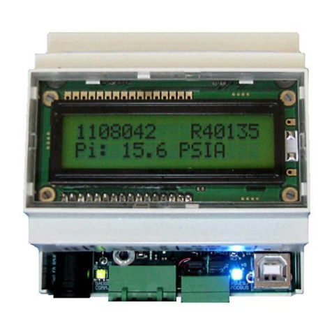
SCOUT-3000
SPS-1500
SPS-3000
Surge Suppressor (Protector)
Surface Choke
In the Appendix of this manual is a copy of the FORTRESS ESP Monitoring System
Field Checklist. This checklist will provide the installer with the ability to follow and
record the installation of the monitoring system. Please follow this guide and use the
checklist provided when installing the Fortress ESP Gauge System.
Customer Service/Support
If any assistance is needed please contact any of our service centers listed below. The
engineers and technicians will be more than happy to provide you with any assistance
needed.
SITE
LOCATION
PHONE
CAPABILITIES
Tulsa, OK,
USA
6540 E. Apache Street
Tulsa, OK 74115 USA
+1.918.834.9600
Headquarters, Engineering,
Manufacturing, Sales,
Service for USA and
Canada
Villahermosa,
Mexico
Comalcalco Num. 111 Fracc, Prados
De Villahermosa, Villahermosa,
Tabasco, Mexico C.P. 86030
993-312-7234
Sales, Service for Mexico
Dubai, UAE
Sercel Dubai
Building ZC02/ZC03 - Blue Shed Area,
P.O. Box 17523,
Jebel Ali Free Zone
Dubai, UAE
+971 4 8832142
Sales, Service for Middle
East
Mumbai, India
SK Oilfield Equipment Co Pvt Ltd.
26,Tarun Bharat Chakala, Andheri
East, Mumbai, 400009 India
91 22 2837 7070
Sales and Service for India
Singapore
Sercel Singapore
68 Loyang Way
Singapore 508758
65 6417 7000
Sales and Service for South
East Asia/Australia

Doc No. 006-0211-00 Rev AD Page 6 of 62
BENCH TESTING AND VERIFICIATION PROCEDURES
Note: Bench test and verification procedures are applicable to all Fortress ESP gauges.
Tools Required
110V Power Source
Either a Sercel-GRC SCOUT-3000 (Surface Readout)
oPortable Scouts will include a twisted wire pair with alligator clips
Or a SERCEL-GRC SCOUT-2200
Bulkhead Cable Assembly
Process Steps for Bench Test and Verification
1. SECURE THE GAUGE to keep the gauge from rolling or moving during
testing.
2. Remove the top shipping cap from the Fortress ESP Sensor.
3. Inspect to make sure no liquid and/or debris is present. (If liquid or debris is
present, contact Sercel-GRC).
4. Connect the red wire (Gauge Signal Wire) from the SCOUT to one of the 3 pins
in the hockey puck as shown in Figure 1 “a”. See page 25 for Surge Panel
connections. See figure 1A and 1B for an illustration of connections from
Scout-3000 to Surge Panel to ESP Gauge.
5. Connect the white/black wire (Ground Wire) to the body of the sensor as
shown in Figure 1 “b”.
6. This next step is applicable to all FORTRESS ESP Sensors EXCEPT the
ESP-1800 and where the motor temperature sensor (Resistance Temperature
Detector, “RTD”.) is not factory installed.
7. Locate the RTD kit (Probe Style or Threaded Style).
8. Locate the two white wires exiting the top of gauge.
9. Temporarily connect the two RTD wires to the two white wires exiting the
gauge. (As there is no polarity, wires can be connected in any way).
NOTE: Installation Procedure for the RTD connection can be found in the
installation section.
10.Power up SCOUT (Red Switch to “On” position)
a. Red switch illuminates indicating SCOUT is powered up. If switch light
does not illuminate, check power connection and/or fuse.
11.SCOUT will begin auto-analyze steps (sync phase and analyze messages on
display).
12.SCOUT will begin displaying gauge data in approximately 2-5 minutes.
13.Record the parameter readings on the Fortress ESP Sensor Checklist in the
Appendix of this manual for test verification records.
a. Bench Test Validation Parameters:
i. Pressure: 0-40 psi
ii. Temperature: ±5º F of ambient
iii. Motor Temperature: ±7º F of ambient
iv. Vibration (If Available): 0-1.2g

Doc No. 006-0211-00 Rev AD Page 7 of 62
a
b
HOCKEY PUCK
Figure 1: Fortress ESP Wiring Configuration
Figure 1A Fortress ESP Wiring Configuration

Doc No. 006-0211-00 Rev AD Page 8 of 62
Figure 1B: Fortress ESP Wiring Configuration
The end of the 3-phase cable will come out somewhere in the center of the ESP
cable spool as shown in Figure 1 above. Follow the steps below to test the gauge
through the ESP cable spool once the cable has been connected to the motor.
Since the SCOUT is powered by 110 VAC, an external power supply will be
needed.
Do not set the SCOUT on the Spooling unit as shown on this trailer.
ONLY CONDUCT THIS CHECK WHILE THE SPOOL IS NOT MOVING.
NEVER AT ANY TIME STEP OVER THE 3 PHASE ESP CABLE.
1. Connect the red wire (gauge signal wire) to one of the 3 phase leads.
2. Connect the white or black wire (ground) to the shielding on the 3 phase cable.
3. Power on the SCOUT.
4. Record the parameter readings on the Fortress ESP Sensor Checklist given in
the Appendix of this Manual.
5. Repeat this for every 10 stands of completion tubing until the last tubing stand
has been assembled.

Doc No. 006-0211-00 Rev AD Page 9 of 62
INSTALLATION PROCEDURES FOR DOWNHOLE GAUGE
Installing the ESP Sensor to the Motor
This procedure outlines the best practices that should be taken in the field. The sensor
can be mounted to the motor before the motor is shipped to the field. In that case, the
procedure will be the same, but probably not done on the back of a flat bed trailer as
shown in these pictures.
1. Layout the sensor so that the three female connections on the Hockey puck
are aligned with the three pins coming out of the motor, and the holes on the
motor base are aligned with the holes on the motor head as shown in Figure 2.
Figure 2. Aligning the motor pins to the Hockey puck.
2. Carefully stab the sensor onto the motor watching closely that the three pins
mate up with the three female connections on the hockey puck. IT IS VERY
IMPORTANT DURING THIS STEP YOU DO NOT TWIST THE SENSOR
WHILE STABBING ONTO THE MOTOR BASE. DOING SO WILL RESULT
IN DAMAGING THE HOCKEY PUCK AND RUINING COMMUNICATION TO
THE SENSOR ONCE THE MOTOR IS STARTED.

Doc No. 006-0211-00 Rev AD Page 10 of 62
Figure 3. Gauge stabbed into motor base.
3. Once the sensor has been stabbed as far as shown in Figure 3, place one of
the motor base bolts through the bolt hole and into the sensor motor head to
make sure that the bolt holes are lined up. DO THIS BEFORE PROCEEDING
TO STAB THE SENSOR FULLY ONTO THE MOTOR BASE.
4. Use of the fill and plug valve to fill the gauge with oil from the gauge plug. Most
customers do not use the fill and plug valve on the gauge and use the one
located on the motor. Below is a description of the plug:
Item
#
Part Number
Description
1
089-0252-00
PLUG, VENT & DRAIN
2
089-0254-00
GASKET, VENT & DRAIN
LEAD SEAL
3
089-0251-00
VALVE, DRAIN & FILL
4
089-0253-00
GASKET, LEAD SEAL
Note: Both gaskets listed above are single-use components. Item 3 (valve) should be
torqued to 210 in-lbs and Item 1 (plug) should be torque to 100 in-lbs.
5. Connect the SCOUT to the motor and gauge assembly. Connect the red wire
(gauge signal) to one of the motor lead power connections and the white or
black wire to the motor housing.
6. Record the parameter readings on the Fortress ESP Sensor Checklist.

Doc No. 006-0211-00 Rev AD Page 11 of 62
Testing the ESP Sensor While Installing Tubing
Figure 4. Spooling Unit.
Installing the Sensor Discharge Pressure Base Adapter (For
ESP& QESP-3500 Gauge Models Only)
Discharge Port Connection
All Dual Pressure gauges are equipped with a Discharge Pressure Port. The
Discharge Pressure Port must be purged with motor oil, vent plugged, and connected to
the hydraulic tubing connecting to the pump discharge sub before being deployed.
Failure to install the Discharge Bleed Plug will result in failure to read the discharge
pressure. See Installation and Troubleshooting guide for instruction to purge discharge
pressure port connections.
Figure 5. Discharge tubing connection.
Compression Fitting
1/8” NPT to ¼” inch
capillary tubing
Discharge
Pressure Bleed
Port Plug
Must be
INSTALLED
before running
gauge into the
well.

Doc No. 006-0211-00 Rev AD Page 12 of 62
THIS OPERATION NEEDS TO BE COMPLETED IN ITS ENTIRETY BEFORE THE
MLE IS CONNECTED TO THE MOTOR.
1. Remove the fitting and ensure that the NPT threads have been Teflon taped.
2. Install the n fitting back into the base.
3. Remove the compression nut and ferrules.
4. Install compression nut and ferrules onto the capillary tubing ensuring the
correct ferrule orientation.
5. Place the capillary tubing with nut and ferrule into the fitting and tighten until one
thread only is visible on the fitting or until the fitting is hand tight using a 9/16”
end wrench.
6. Nipple up BHA and Discharge Sub.
7. Leave the fitting on the discharge sub hand tight so that it will leak fluid slightly.
8. Once the BHA and discharge sub is installed, POOH BHA and connect a
pressure test system to the Discharge pressure bleed port.
9. Remove pressure test system and install plug in port.
10.Fill the line with hydraulic fluid until fluid exits the pressure bleed port.
11.RIH BHA and tighten the pressure fitting on the discharge pressure port.
12.POOH BHA and remove plug from port.
13.Immediately install the pressure test system and pressure test to 5Kpsi for 10
min.
14.If the pressure remains constant +/- 20 psi, then the installation is complete, if
not, then repeats Steps 1-13.
Megger testing motor and cable
The motor and cable may be Megger tested if required using the following guidelines:
The output voltage of a Megger will exceed the breakdown voltage of the protective
MOV mounted on the fuse block. The MOV will conduct if a Megger is used, giving
incorrect readings. Disconnect the three-phase choke and fuse block from the motor
cable before testing. Do not Megger test the downhole equipment while any of the
surface components are connected to the motor power cable.
NOTE: MEGGER TEST THE SENSOR IN REVERSE POLARITY ONLY!!

Doc No. 006-0211-00 Rev AD Page 13 of 62
Installing the Resistance Temperature Detector “RTD” (For
Non-Factory Installed RTDs, Probe Style)
All ESP Gauges monitor Motor Temperature with a Platinum 1K RTD. There are
several RTD Motor Temperature Probe options including Probe, Threaded, and
customer supplied. Motor Temp probes are mounted inside the gauge assembly and
placed against the Motor Windings for maximum temperature transfer and fast
response. Motor Temperature Sensors can be ordered as an accessory or wired
permanently inside the gauge eliminating field connection concern.
The following procedure appears much more complex than it actually is and can be
performed in either the field or shop environment. Also included in this document is the
wye point solder procedure that Manufacturing uses.
Motor RTD Connection Instructions
a. The first step is to determine where the RTD is going to be placed. It can be
either inside the ESP motor oil passage or inside the Sercel-GRC gauge. Inside
the gauge is the safest and is the least likely to come in contact with rotating
motor components, but it will be slower in responding to temperature variations of
the ESP motor. Placing the RTD inside the motor oil passages provides faster
response times to temperature changes, but runs the risk of contacting rotating
parts.
b. Shorten the two wires coming from the gauge for the RTD to match where you
have determined to place the RTD. If it’s going inside the motor oil passage
secure the wiring and its excess to insure that the RTD is not drawn further into
the oil passage by the oil flowing through it. This prevents the RTD from coming
in contact with the rotating internal parts of the motor. Also insure that the wiring
will not come in contact with the end of the rotating motor shaft located where the
motor and ESP gauge are mated together. If the RTD is being placed inside the
gauge do not coil up the excess wire inside gauge but instead shorten the wires
and then insert the RTD and wiring back into the gauge. The reason for not
coiling the excess wire up and placing it inside the gauge is this can possibly
allow motor noise to show up on the motor temperature readings.
c. Strip 1/4” to 3/8” of insulation from the RTD and gauge wires.
d. Cut a piece of high temp heat shrink tubing, around 2.5”, and slide it over and
past both stripped gauge wires.
e. Using two more pieces of high temperature heat shrink tubing, around 1.5” long,
slide each piece over and past each individual gauge wire. The result should look
like the example in Figure 6.

Doc No. 006-0211-00 Rev AD Page 14 of 62
Figure 6. Three pieces of shrink tubing on gauge wires.
f. Twist one RTD wire and one RTD gauge wire together creating a splice so that it
appears as a straight wire and not two wires side by side. At this time solder the
two wires together using high temp solder. Do the same step for the other two
wires (one from the RTD and the other from the gauge).
g. Slide the heat shrink tubing down over each individual soldered bare wire and
heat shrink the two pieces of tubing using a hot air gun (heat gun). The solder
joint should be located in the center of the length of the tubing and the result
should appear as shown in Figure 7.
h. From step c, now slide the longer piece of heat shrink tubing over both wires so
that the solder joint is centrally located inside the tubing as shown in Figure 8.
Figure 7. Heat shrink tubing over solder joints.
Solder joint located
at the center of the
heat shrink tubing.

Doc No. 006-0211-00 Rev AD Page 15 of 62
Figure 8. Long piece of heat shrink tubing over both wires.
Finally, replace the wye point if you have removed it. Attach the Scout-3000 or portable
Scout to any of the motor terminals of the wye point or to the gauge wire if not using our
wye point. Turn on the Scout and check/record gauge readings.
Place the RTD in the position you had determined and reassemble the gauge and
motor. Re-check and record readings using the Scout attached to the top of the motor
on one motor lead.
Wye Point Replacement
If you do have to remove the wye point, below is the GRC procedure that is used when
Manufacturing is attaching the wye point.
Purpose
The purpose of this procedure is to give instructions on how to solder the
communication wire to the WYE terminal for ESP gauges.
Cautions and Warnings
Ensure there are no nicks on the conductor of the communication wire when stripping.
Ensure there are no sharp edges on solder joint of wire and terminal. Ensure shrunken
heat shrink does not back off from the terminal. Read entire procedure before initiating
procedure.
Equipment needed
2 Heat Shrink Wraps 1 ½ inches long, P/N: 133-0051-00
Needle nose pliers
Heat Gun
High Temperature Solder, P/N: 140-0001-00
Flux
Isopropyl Alcohol
WYE Adapter
Communication Wire (From Assembly 90C2025, not to be confuse with the RTD
white wire)
Terminal, P/N: 90B1863

Doc No. 006-0211-00 Rev AD Page 16 of 62
Procedure
Cut P/N 037-0050-04 off from the communication wire, refer to Appendix Fig. A1.
Thread the communication wire through the hole on the terminal.
Be sure not to use the RTD wires as all wiring from the choke is white.
Fold the excess wire back towards itself making a loop. Refer to Figure 52.
Figure 9. WYE Connector Shown with the
Communication Wire Prior to Crimping.
Any excess wire extending beyond the insulation of the wire should be removed.
Before soldering, gently crimp the wires with needle nose pliers to close the gap of the
wire loop. Refer to Figure 10.
Figure 10. WYE Terminal Shown with the
Communication Wire After Being Crimped.

Doc No. 006-0211-00 Rev AD Page 17 of 62
Now solder the wire to the terminal with the aid of flux making sure not to leave any
sharp edges. Refer to Fig. 11. After soldering, clean the solder with alcohol and slide
the clear plastic wire insulator to the solder joint. Refer to Fig. 11.
Figure 11. WYE Terminal Shown with the
Communication Wire Soldered.
Slide one piece of heat shrink tubing down to the hex base of the terminal. Apply heat
to shrink the first heat shrink tubing before applying second layer of heat shrink
tubing. Refer to Figure 12.
Figure 12. WYE Connector Shown with the
First Heat Shrink Tubing Un-Shrunk.

Doc No. 006-0211-00 Rev AD Page 18 of 62
Now slide the second piece of heat shrink tubing down to the base of the threaded pin.
This will go over the first heat shrink tubing. Refer to Fig. 13a.
Figure 13. WYE Connector Shown with the
Second Heat Shrink Tubing.
Apply heat to the heat shrink to complete the assembly. Refer to Fig.13b for final
assembly.
Figure 13b. WYE Connector Terminal Shown with
Both Heat Shrink Tubing Shrunk.

Doc No. 006-0211-00 Rev AD Page 19 of 62
! CAUTION ! Lethal Voltages Present Inside Enclosure.
Remove power anytime the front panel of the Scout-3000 is removed.
There are potentially dangerous voltages present!
INSTALLING THE SURFACE INTERFACE EQUIPMENT
SCOUT-3000 Installation
Figure 14 shows a typical wiring and installation schematic for the ESP surface
equipment. Figure 15 describes the specific connections of a Scout-3000 to a gauge.
Connections are also detailed for the 4-20mA Current Loop and Modbus.
Figure 14. SCOUT and Suface System Wiring Diagram

Doc No. 006-0211-00 Rev AD Page 20 of 62
Signal Name
Recommended Wire Colors
AC Power-In
Black-Live, White-Neutral, Green-Earth Gnd
Gauge
Red-Signal (+), Green-Return (-)
4-20mA #1
Orange/Gray
(Connections for Scout-3000 w/ Optional
4-20mA Current Loop)
4-20mA #2
Blue/Violet
(Connections for Scout-3000 w/ Optional
4-20mA Current Loop)
Modbus
Blue/Violet
(Connect to Pins 1 and 4)
Figure 15. Scout-3000 Wiring and Connections
SPS-3000 Installation
The connections for the SPS-3000 are shown in Figure 16 below.
Gauge: +Connection to ESP gauge signal. –Connection to dedicated wellhead
ground.
VDC: Connections to a +12 to 18VDC and Ground.
ModBus: TR- and TR+ Connections to ModBus master
Figure 16. SPS-3000 Connections
SPS-3000
Sig+ Grd- 12-18V Grd TR+ TR- TR+ TR-
Power
Supply
12-18 VDC
Surge Panel
(to Wellhead
Ground)
ModBus Master
or
485 Converter
ModBus
Slave
+
+
-
+
+
+
-
+
+
+
-
+
+
+
-
+
This manual suits for next models
11
Table of contents
Other Sercel Measuring Instrument manuals
Popular Measuring Instrument manuals by other brands

Texas Instruments
Texas Instruments MSP-SA430-SUB1GHZ quick start guide

Dorrough Electronics
Dorrough Electronics 40-A instruction manual

PCB Piezotronics
PCB Piezotronics 422M136 Installation and operating manual
Sper scientific
Sper scientific 300001 instruction manual

inbody
inbody BSM270 user manual
GHM
GHM DeltaOHM LPUVA02 operating manual
