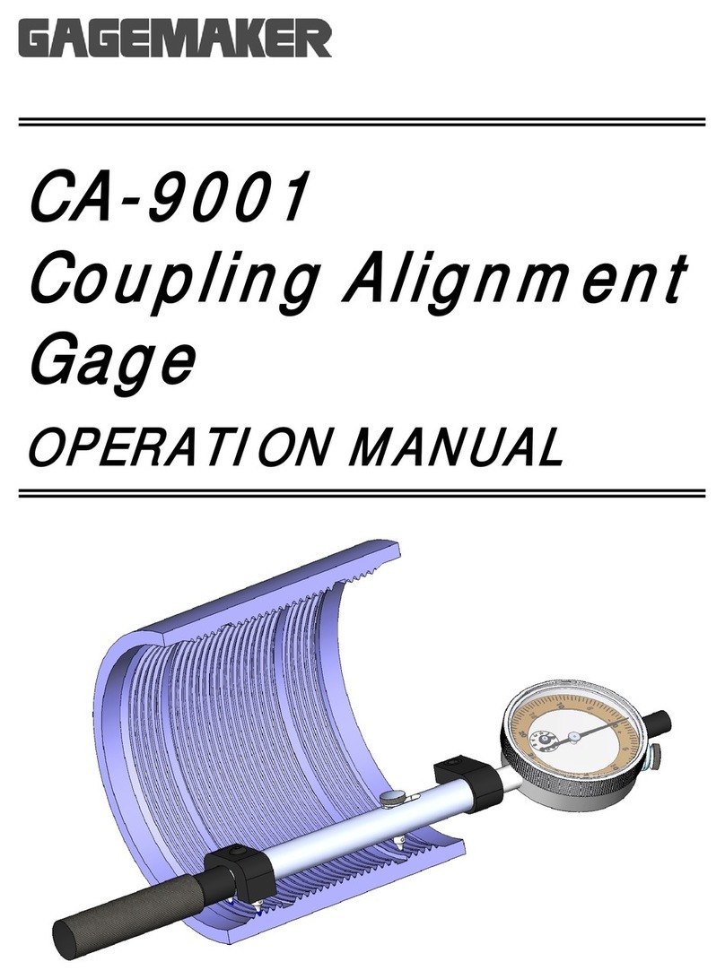
Lead Gage Operation Manual Model LG-5003
4Copyright © 2014 Gagemaker. All rights reserved
Congratulations! Your decision to purchase a Gagemaker product above all others on the market
demonstrates your confidence in our quality and workmanship.
To ensure the high performance and operation of our product, we urge you to use the included reference
materials. They contain important information for proper setup and use of the equipment. Also, we
recommend that you follow the care and maintenance tips in this manual to keep the equipment working
in top condition.
If your questions have not been addressed in our reference materials, contact your local
representative or a customer service representative at 713-472-7360.
Introduction
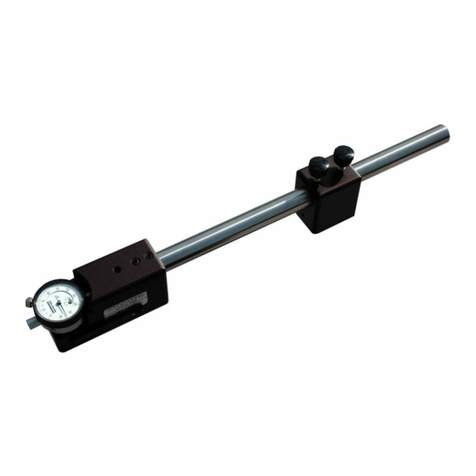
The lead gage inspects both internal and external thread lead using contact points that seat in the
threads of a part. Thread lead is the distance between threads, measured on a plane parallel to the
centerline of the threaded part. The pitch of the thread determines the diameter of the contact points
required for taking measurements (refer to the tables for ACME, Stub ACME, UN and API Threads in
the Setup Procedures section of this manual).
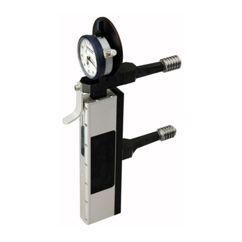
Gagemaker’s lead gage, Model LG-5003, uses the three-point system, to inspect thread lead. Two
fixed contact points at the rear of the gage and one moveable contact point at the front of the gage
provide complete stability when taking thread lead measurements. This unique design does not require
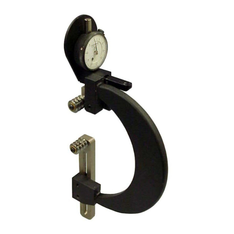
sweeping to obtain measurements. By removing the third contact point, the LG-5003 is easily converted
to a conventional lead gage, which uses two contact points and requires sweeping the gage to obtain
the shortest lead dimension.
Before inspecting parts, the lead gage must be preset to a nominal predetermined dimension, using a
lead gage setting standard. These setting standards are manufactured according to ANSI and API
specifications with grooves ground at precise increments. The increments are normally set at ½”
intervals from 1” – 4”. Lead standards are available for ACME, Stub ACME, UN and API threads (refer
to the table in the procedure for Zeroing the Lead Gage in this manual).
To inspect parts, seat the two rear contact points of the gage into the thread of the part. Then, seat the
moveable contact point at the front of the gage in the thread. Apply pressure to the nose of the gage
with an index finger to get an indicator reading. It is recommended that the gage be zeroed periodically
during use to maintain accurate readings.
Technical Support
Phone: 713-472-7360
Hours: Monday – Friday 8AM – 5PM (CST)
Product Information and Updates
Visit our web site at: www.gagemaker.com
