Neptune G-50-1 Instruction Manual

NEPTUNE
GLYCOL FEED SYSTEM
Models G-50-1, G-50-1A, G-50-2A, G-100-1A, G-100-2A
Lansdale, PA 19446 Tel: 215-699-8700 Fax: 215-699-0370
REV NO 6 – 01/08/04
ZL106838
OPERATING &
INSTRUCTION
MANUAL

I.
GENERAL DESCRIPTION
Neptune Chemical Pump Company’s Glycol Feed System is intended for the automated
addition of glycol into closed loop chilled and hot water systems. The Glycol Feed System
automatically maintains pressure in the loop by adding glycol solution to make up for
losses, which occur due to leakage.
Glycol addition is controlled by a pressure switch with adjustable low and high set points.
When the pressure in the loop reaches the low set point, the pump begins to feed glycol
into the system until the high set point pressure is achieved and stops the pump.
I.
MODELS
The Model G-50-1 or G-100-1 is provided with a 50 or 100 gallon polyethylene tank
mounted in a steel frame, 1.5 gpm bronze rotary gear pump (optional 3.0 gpm pump), float
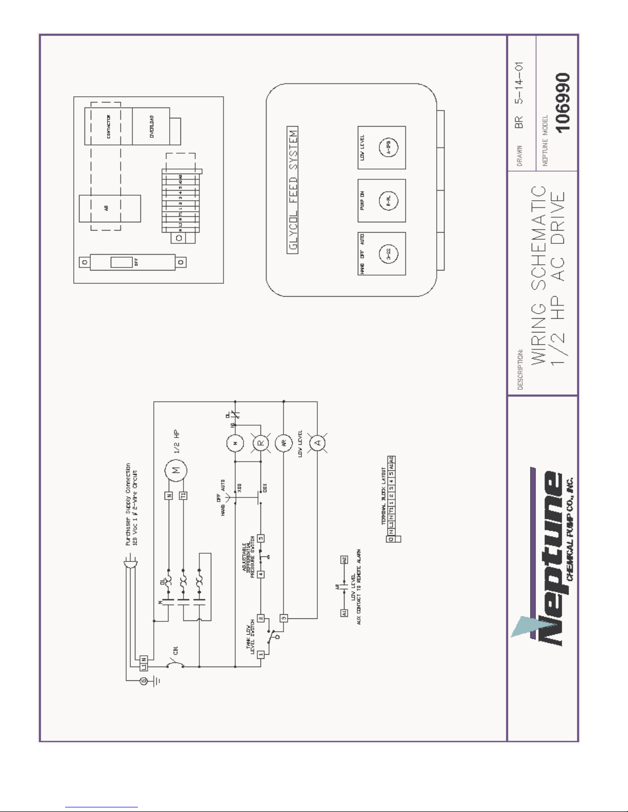
switch and NEMA 4X control panel. The control panel features a HAND/OFF/AUTO
selector switch for the pump motor, ON indication light for the pump, LOW tank level
indication light and power cord with plug (115V, 60c). The pump suction piping includes
a PVC ball valve and cast iron “Y” strainer. The pump discharge assembly includes a PVC
ball valve, brass check valve, pressure switch, bronze relief valve and pressure gauge.
The Model G-XX-1A is identical to the G-XX-1 and has the addition of an audible
alarm, as well as light for low level tank indication.
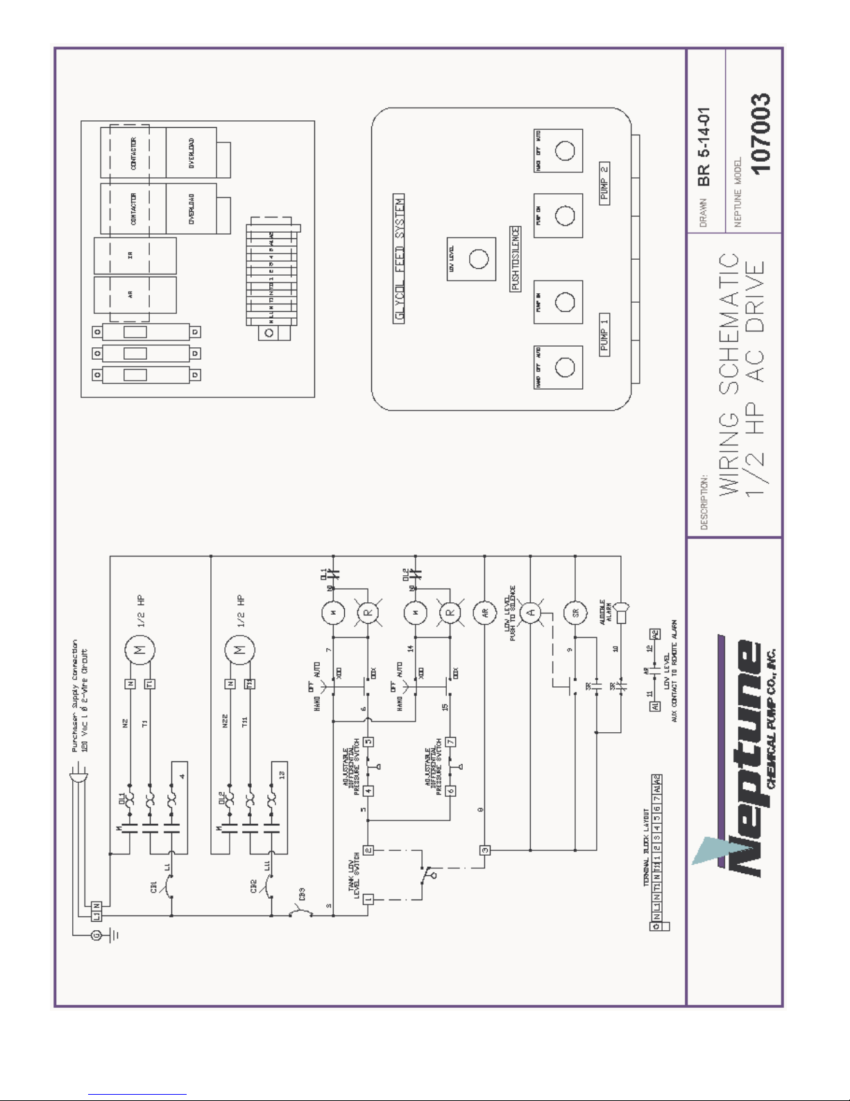
The Model G-XX-2A is capable of feeding glycol to two separate closed loop systems
and includes two separate pumps, as well as suction and discharge assemblies.
The LP designation at the end of a model number (ex. G-XX-1-LP) indicates that a 3.0
gpm pump has been provided in place of our standard 1.5 gpm pump.
All glycol systems are provided with a dry contact for remote alarm.
II.
OPERATION
The glycol feeder is provided with a control panel with HAND/OFF/AUTO selector
switch.
When the panel is switched to the AUTO position, the pump is actuated via the pressure
switch, which is mounted in the discharge assembly and sensing the pressure in the loop.
The pressure switch is pre-set to start the pump at 12 psi and stop the pump when 30 psi in
the loop is achieved. The adjustment range for the standard pressure switch is 10-45 psi to
start the pump and 20-60 psi to stop the pump. The minimum differential pressure
between the cut in and cut out set points is 10 psi and the maximum is 30 psi. The float
switch in the bottom of the tank will stop the pump if the glycol solution in the tank gets to
low level.
The MANUAL position of the selector switch in the panel will allow the pumps to run and
inactivate both the pressure switch and the level switch.
PLEASE READ THIS
The initial setting of the pressure switch is critical
to the proper operation of the glycol feeder.
WARNING
The pressure relief valve is factory set at 60 psi.
DO NOT operate the glycol feeder above 100 psi.
If your application requires a higher operating
pressure, consult the factory.

TROUBLESHOOTING
PROBLEM PROBABLE CAUSE
Pump is running but is 1. The motor rotation is incorrect. The
not pumping anything proper rotation of the motor is counter-clockwise when
looking at the motor shaft. Check the wiring diagram
on the motor or the attached motor diagram for proper
wiring.
2. On simplex single pump systems – Model G-XX-1 and
G-XX-1A. The motor should be wired for 115V
counter-clockwise rotation. See further information on
the pump, which is attached.
3. Duplex or two pump systems, Model G-XX-2A, require
one pump motor to be wired counter-clockwise and the
other in a clockwise rotation. Looking at the front of
the Model G-XX-2A, the control panel facing you, the
pump motor on the left should be wired counter-
clockwise and the pump motor on the right should be
wired for a clockwise rotation.
Pump is not running when 1. The low level float switch may be
HOA switch is in the AUTO actuated. The low light will be on and
position the audible alarm will sound on some
models. Add glycol to the tank until
the level switch is satisfied.
2. The pressure switch in the discharge piping has been
satisfied. The pressure switch is factory set to actuate
the pump at 12 psi and shut-off at 30 psi. See pressure
switch information for pressure switch adjustment,
which can be found on the inside cover of the pressure
switch.


Bronze Rotary Gear Pumps
Installation, Operation, and Maintenance Instruction
INTRODUCTION
Congratulations for choosing an Oberdorfer pump,the Industry Standard for quality since 1890.
Construction
Bronze Rotary Gear standard pump housings and helical gears are made of top quality bronze. Shafts are stainless steel. Pumps are available
with bronze bearings and grease fittings or with carbon bearings which require no lubrication. Dynamic seal arrangements include packing,
lip, or mechanical seals for a variety of application requirements. Static cover o-ring seals eliminate gasket problems.
Application Range
Bronze Rotary Gear pumps are of the external gear positive displacement type, displacing a finite volume of fluid with each shaft revolution.
As such, capacity varies in direct proportion to pump speed. They are suited to handle clear lubricating and non-lubricating fluids, with PH
ranging from 4 to 11, and temperatures to 400F. These pumps handle viscous fluids to 100,000 cps (462000 SSU) at reduced shaft speeds, with
flow rates to 175 GPM (662 LPM), differential pressures to 150 psig (10.3 BAR), and suction lift capability to 20 feet (6.1 meters) for new
pumps.
Field Inspection
Bronze Rotary Gear pumps may be readily inspected in the field usually without removal from the drive or system plumbing. Simply remove
the cover screws to pull the cover. Before attempting an inspection, follow safety precautions and be sure to read and understand this
manual.
New Pump Receipt Inspection
Upon receipt, check for obvious shipping damage and completeness to purchase order requirements. Shortages or damage should be reported
immediately to the carrier and to your Oberdorfer distributor. Occasionally during shipment, possible misalignment or other damage
including cracked mechanical seal faces can occur. As such, customers are advised to test the pump with water in a convenient location prior
to installing into the intended system.
Storage
If the pump is to be stored prior to installation, it is recommended that it be left in the original shipping carton with all shipping plugs in
place and stored in a dry environment avoiding temperature variations. Contact the motor manufacturer for specific motor storage
information.
Records
These instructions should be kept in a convenient location for ready reference. The manual should be read carefully by persons responsible
for installation, operation, and maintenance of the equipment. For ease of reference, a copy of the order should be kept with the manual.
Write down the pump model number as shown on the pump nametag, and the date the unit was placed into service.

BRONZE ROTARY GEAR PUMP INSTRUCTIONS continued …….
INSTALLATION
Site Preparation
Choose a site that allows easy access to the pump for maintenance. Consider protection from the elements. Guard against drips and spray
from nearby equipment. Choose a solid foundation for mounting. If noise is a concern, consider a rubber pad under the pump base to
dampen.
Flow Direction
Gear pumps will perform equally well in either direction however care must be taken for pumps equipped with integral pressure relief valves.
To change flow direction effectively reversing the suction and discharge ports, simply switch driver rotation by following motor wiring
diagram instructions and change the location of the relief valve as shown below. Most pump motor units are factory supplied with
counterclockwise shaft rotation (when viewing the pump from the shaft end).
Suction Plumbing
Suction side plumbing considerations are key to desirable pump performance. Minimize head loss by assuring sufficient pipe size (especially
important for highly viscous services). Generally the same size pipe as the pump ports is adequate. For long runs (beyond 3 feet) or viscous
fluids, use one or two pipe sizes larger. Strive to keep the lines as short and straight as possible. If flexible lines are used, they should be
selected to prevent wall collapse. To keep the pump from being starved or running dry, be sure there is sufficient fluid supply. A flooded
suction is generally preferred. Suction lifts over 3 vertical feet and long horizontal runs (beyond 3 lineal feet) require a foot or check valve
below the level of the liquid being pumped. When taking suction from a tank or vessel, position the inlet above the maximum expected level
of solids. Use full-bore ball valves or gate valves to minimize restriction. Suction strainers should be properly sized to minimize pressure
drop and positioned for easy cleaning access. If start-up screens are used, be sure they are removed prior to placing the system into regular
operation. Orient lines so as to prevent formation of air pockets. Be sure all joints are tight. Flush out all suction lines prior to installing the
pump.
General Piping
For further ease of maintenance, use union fittings to connect the pump to the system. Install a discharge priming tee for convenience. Do not
spring the piping to connect the pump. Use piping supports or hangers as required. When necessary, provide for thermal expansion and
contraction to avoid placing strain on the pump.
Alignment
Proper alignment is key to seal and bearing performance. Improper alignment can lead to premature pump failure. Check the alignment
carefully between the pump and the drive.
Belt Drive
Though alignment is not as critical as direct connected, ensure that the pump and motor shafts are parallel and in line. For units suitable for
belt drive, be sure that the belt tension is adequate (per the belt manufacturer’s recommendation) but do not overtighten. For heavy pulley
loads, models are equipped with external ball bearing supports. A single 1/2” (A or 4L section) V-belt is satisfactory for drive speeds up to 1
HP 3450 RPM. For larger drive sizes, double-V belts are recommended. Install guards around all moving parts in accordance with OSHA to
prevent personal injury.
Fasteners
Unless the pump has been shipped directly from the factory, it is recommended to check all bolts and nuts for tight-ness to eliminate possible
leakage problems or destructive vibration.
Pressure Relief
Discharge lines should be fitted with properly sized line pressure relief valves to protect both the pump and the system. Pumps equipped with
integral internal bypass relief valves are intended as a safety device against intermittent overpressurization. They are not designed for
continuous use and can lead to overheating. In these instances, a line pressure relief valve is required. The relief outlet should be piped back
to the suction vessel.

BRONZE ROTARY GEAR PUMP INSTRUCTIONS continued …….
Flow By-Pass
When a flow by-pass system is used to control output from the pump, the bypassed fluid should be directed back to the suction vessel to
avoid recirculation heat build-up. In cases where this is not possible, connect to the suction at least 10 pipe diameters length away from the
pump inlet. Provisions for cooling should be made in the event of recirculation heat build-up.
Pump Driver Mounting
Adapter kits (including bracket, coupling components, and hardware) are available for Bronze Close Coupled Gear pumps allowing
connectivity to NEMA and IEC motor frames. Assembly instructions are included with each kit. Adapterless motors, carbonator mounts, and
electric clutches are available for some models. Base mount kits (including baseplate, coupling components, coupling guard, and hardware)
are available for Bronze Pedestal Gear pumps. Contact your Oberdorfer representative for additional information.
OPERATION
Pre-Startup
Prior to start-up, recheck installation as described above. Verify desired rotation by jogging the motor and make corrections if necessary.
Before initial startup, pre-wet the gears and make sure the pump is adequately primed. Failure to do so could cause immediate damage to
pump components. Make sure that discharge valves are open.
Startup
Start pump and check for proper operation. Adjust packing (if applicable) as necessary, allowing adequate time to run in. Do not overtighten
the packing else damage to the packing and the shaft can occur. A properly packed and adjusted packing nut will leak at about 10 drops
every 3 to 5 minutes. Tighten packing nut only while shaft is rotating. Lip and mechanical seal versions require no adjustment. If the pump’s
bearing areas or seal area runs hot, shut the pump down and determine the cause. For units equipped with integral pressure relief valve, the
factory setting is usually 50 psig. It is recommended that the setting should be 5 psig above the operating pressure in the discharge line. To
increase the set point, turn the by-pass valve adjusting screw clockwise. If start-up screens were used, be sure they are removed prior to
placing the system into regular operation. Depending on suction conditions, it may be necessary to reprime the pump for subsequent restarts.
MAINTENANCE
Frequency
Since each installation differs, the frequency and extent of pump maintenance is best established based upon past performance. Keeping
detailed maintenance records of past performance aids in determining future preventative maintenance intervals. During routine operating
inspections, pay particular attention to seal and bearing areas of the pump. Consult the motor manufacturer for motor maintenance
instructions.
Changing Applications
Verify that all wetted parts of the pump are compatible with the new fluid to be handled and that the motor is adequately sized. Check with
your Oberdorfer distributor if in doubt.
Inspect for Wear
If your Bronze Gear Pump exhibits reduced flow, an inability to maintain pressure, is noisy or performs otherwise abnormally, first refer to
the Troubleshooting Matrix on back. If the problem persists, the pump should be inspected for wear or damage. Oberdorfer Bronze Gear
pump internals may be readily inspected in the field usually without removal from the drive or system plumbing. Simply remove the cover
screws to pull the cover. Full pumpremoval and complete disassembly may be needed for a comprehensive inspection. Contact your local
authorized distributor or the Oberdorfer factory.
BRONZE ROTARY GEAR PUMP INSTRUCTIONS continued …….

Mechanical Seals
Pumps equipped with mechanical seals are of the standard pusher bellows type or wedge style. They can be expected to provide long and
troublefree service provided:
1) Seal materials are compatible with pumped fluid and properly applied to the service.
2) Adequate cooling and lubrication is provided
3) Dry running is avoided
4) Abrasives are kept away from the seal area
5) Pump and driver are properly aligned
Detailed mechanical seal inspection and replacement instructions are included with Oberdorfer Repair Kits.
Lip Seals
Pumps equipped with lip seals are of the metal cased, spring energized, single lip style. These are intended to provide minimum friction drag
with positive sealing and again should be maintenance free provided the same conditions for mechanical seals are met as well as:
6) Avoid scouring of the shaft in the lip seal area due to contaminated abrasives
7) Avoid excessive seal lip contact pressure on the pump shaft due to excessive pump pressure.
These are readily replaceable by pressing out the old seal and pressing in a new replacement.
Packing
Pumps equipped with teflon or graphoil packing require periodic adjustment as described above in the Startup section to avoid excessive
leakage. Eventually all the packing in the pump will become deteriorated and will have to be replaced.
Recommended Spares
Repair kits are available for all Oberdorfer Bronze Gear Pumps. Each kit comes with detailed instructions. For the proper kit, contact your
Oberdorfer Distributor or the factory.

PRESSURE SWITCH INSTRUCTIONS
SQUARE D
Commercial Pressure Switch
Class 9013, Model FSG29J99
Model FSG29J99
CUT-OUT RANGE 20-60 PSI
ADJUSTABLE RANGE 10-30 PSI
CUT-IN RANGE 10-45 PSI
PRESSURE CONNECTION : ¼” NPT EXTERNAL
T
ECHNICAL
T
ERMS
Operating Points (Settings)
Every pressure switch has two operating points; one on rising pressure and one of falling pressure. The operating point on rising
pressure is referred to as the TRIP POINT or cut out for pumps and compressors and the operating point on falling pressure is
referred to as the RESET POINT or cut in for pumps and compressors. These operating points are called the SETTINGS of the
switch. — TRIP POINT (rising pressure)
— RESET POINT (falling pressure)
Differential
The differential is the difference in pressure between the trip point (cut-out) and the reset point (cut-in). It can be adjustable or
nonadjustable (fixed).
Example: Cut-in 30 psi
Cut-out 50 psi
Differential 20 psi (50-30 psi)
Range
The range is the pressure limits within which the operating points (settings) can be adjusted. The range of the Class 9013
pressure switch is referenced to the operating point on rising pressure (trip point). The differential subtracts from the trip point
setting. During the normal operating cycle, system pressure should never exceed the upper limit of the range when using a
diaphragm actuated switch. This will greatly reduce the life of the diaphragm.
Maximum Allowable Pressure
Maximum allowable pressure is the pressure to which a switch can be subjected without causing a change in operating
characteristics, shift in settings, or damage to the device. Pressure surges may occur in a system during the start up of a
machine or from valve operation. Surges are not normally detrimental to the life of a switch if the surge is within the maximum
allowable pressure rating of the switch. Diaphragm actuated switches should not be subjected to more than 10 surges per day.
More frequent surges will greatly reduce the life of the diaphragm.

PRESSURE SWITCH INSTRUCTIONS continued …..
SET POINT ADJUSTMENTS
The pressure switch is set at the factory to the operating point(s) marked on the outside of the switch housing. Before
readjusting the switch, cyle it to determine actual operating points.
Non-Adjustable Differential
The range adjustment nut ( Item H, Figure 3 ) or knob ( Item C, Figure 3 ) adjusts both setpoints by the same amount.
To adjust the operating points :
1. Place a flat blade screwdriver in a range adjustment nut slot.
2. Rotate the nut to the left to increase the operating points or to the right to decrease the operating set points.
Adjustable Differential
The range adjustment nut or knob determines the decreasing setpoint. The adjusting screw ( Item J, Figure 3 ) determines the
increasing setpoints. To adjust the operating points :
1. Adjust the decreasing setpoint ( see steps 1 and 2 above ).
2. Turn the adjusting screw clockwise ( to raise the increasing setpoint ). This adjustment does not affect the
decreasing setpoint.
FIGURE 3
INSTALLATION INSTRUCTIONS LL-3 (L-30N)
LIQUID LEVEL SWITCH
MODEL L30N LIQUID LEVEL SWITCH
INSTALLATION AND OPERATING INSTRUCTIONS
Installation:
The L-30 liquid level switch is supplied with a 1-1/2” or 1-1/4” X 1 bushing threaded in place
with 2 to 3 wraps of teflon tape, which must be intact or renewed if bushing and switch are
separated before assembly in tank. Care must be exercised when threading the bushing
into plastic or metal fittings. Apply a minimurn of 2 to a maximum of 3 wraps of teflon tape
to threads of bushing - this is especially important if unit is to be used in metal fittings where
coarse METAL THREADS could gall plastic if not lubricated. The plastic bushing CAN BE
CRACKED if the main body of the flow switch is tightened into it FIRST. Cracking will not
occur if the bushing is FIRST tightened into the pipe or tank fitting and THEN the L-30 body
is tightened into the bushing.
Thus:
1). Teflon tape thread and tighten plastic bushing into pipe or tank fitting.
2). Teflon tape thread and tighten L-30 switch into PLASTIC bushing by applying wrench to
hexagon section. Repeat steps I and 2 until ARROW on body points to UPWARD and
threads are, leak tight.
Plumbers'tools such as pipe wrenches are not recommended. If possible use a "Ridgid"
type wrench where the smooth jaws closely fit the hexagon section.
Electrical Wiring:
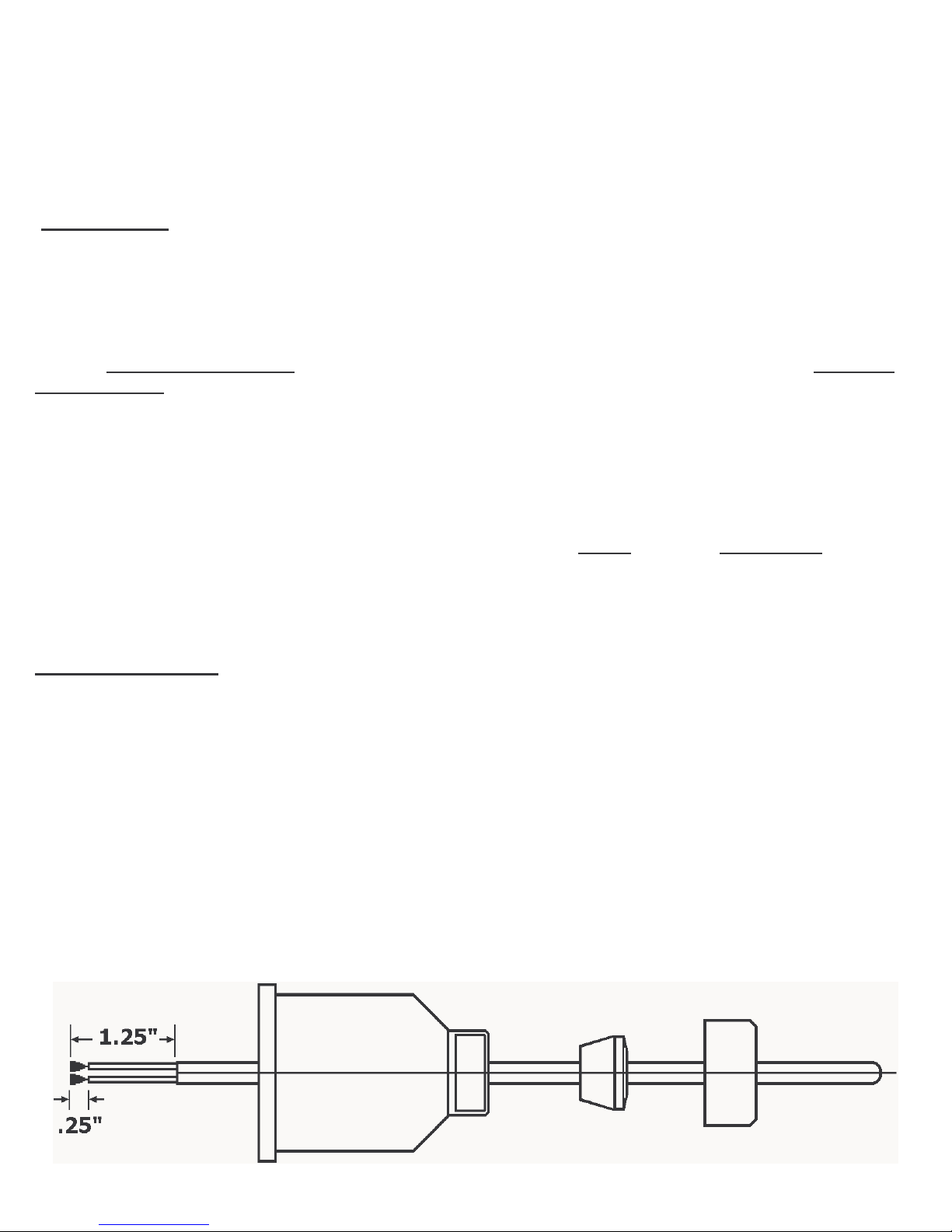
1). Remove gland nut, grommet and switch cover.
2). Strip outerjacket of electrical cord back
3). Slip on terminals are
individual conductors supplied with each switch. approximately 1-1/4". Strip insulation
from back approximately 1/4". Remove from switch terminals and
and crimp on or solder to electrical leads.
4). Feed electrical cable through gland nut, grommet and switch cover as shown.

MODEL L30N LIQUID LEVEL SWITCH
INSTALLATION AND OPERATING INSTRUCTIONS
5). Apply slip on terminals to appropriate contacts of micro switch. Slide cover down
cable and fasten to body of switch with four screws provided. Slide grommet down cable
until outer jacket is level with small end of grommet per illustration page 2. Push
grommet into tapered end of cover. Hold cable jacket to prevent rotation and thread
gland nut firmly on to cover.
Fig. 1: Wiring schematic for power applied to load when liquid level is less than set point
(power to load interrupted when level increases to above set point).
Fig. 2: Wiring schematic for power applied to load when liquid level is greater than set
point (power to load interrupted when level decreases to below set point).
Microswitch actuation point may be monitored by an audible click or with an OHM meter
before connecting line power to the terminal strip or by monitoring the voltage supplied to
the load through the microswitch.
Figure 1 Figure 2
This manual suits for next models
4
Table of contents
Other Neptune Industrial Equipment manuals


