3
Installation Manual
Saturn Bm CONTENTS
Nera SatCom AS reserves the right to change the design and specifications of the equipment without notice.
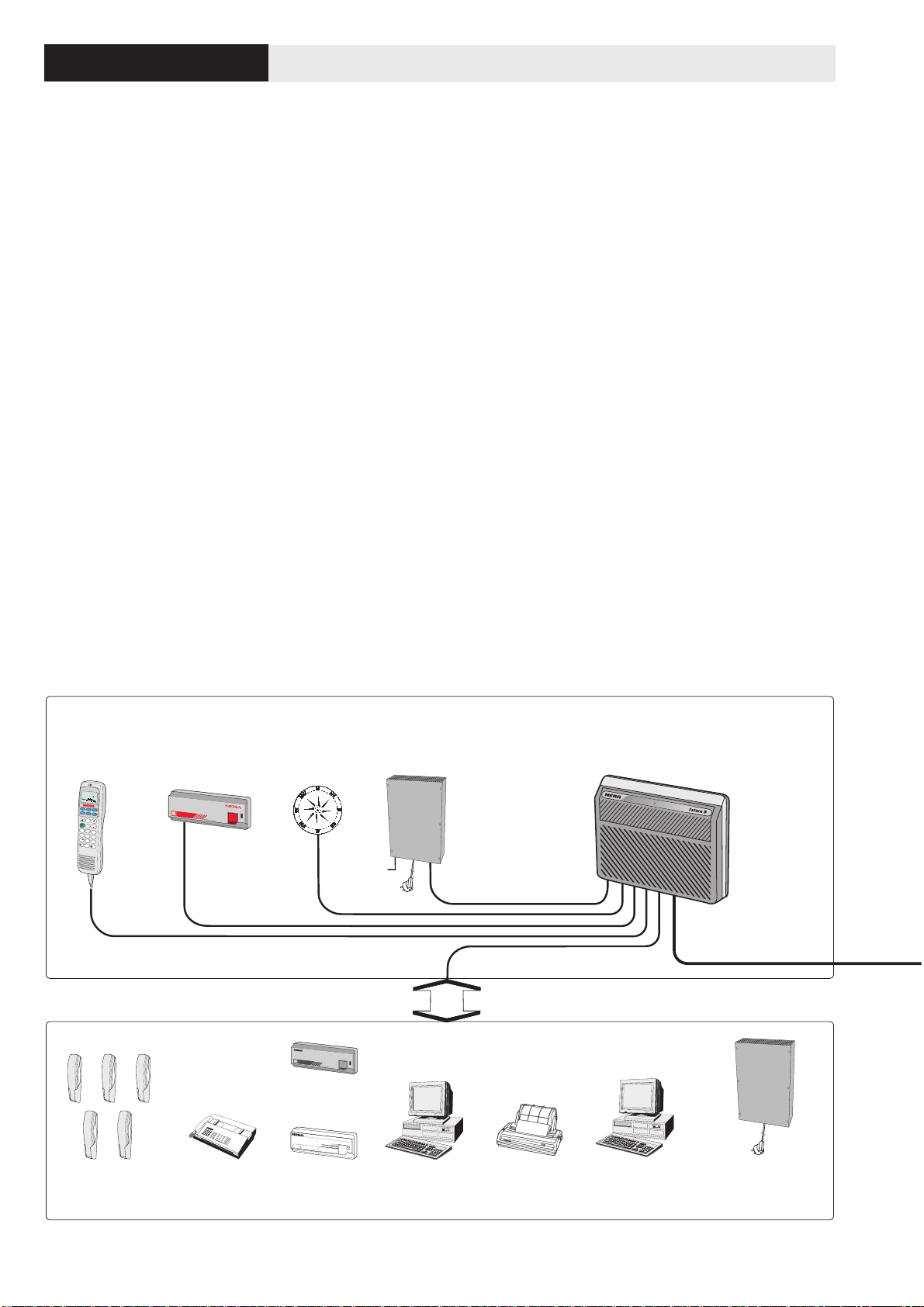
Below Decks Equipment – BDE . . . . . . . . . . . . . . . . . . . . . . 4
Above Decks Equipment – ADE . . . . . . . . . . . . . . . . . . . . . . 5
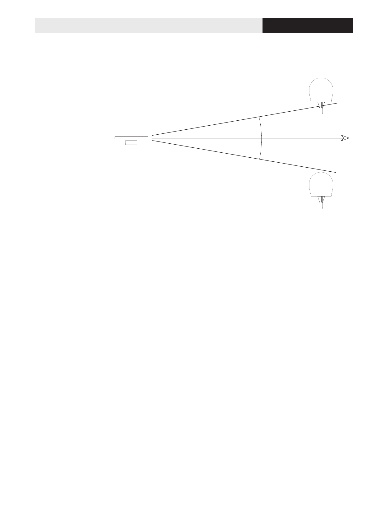
Placing the Antenna . . . . . . . . . . . . . . . . . . . . . . . . . . . . . . . 6
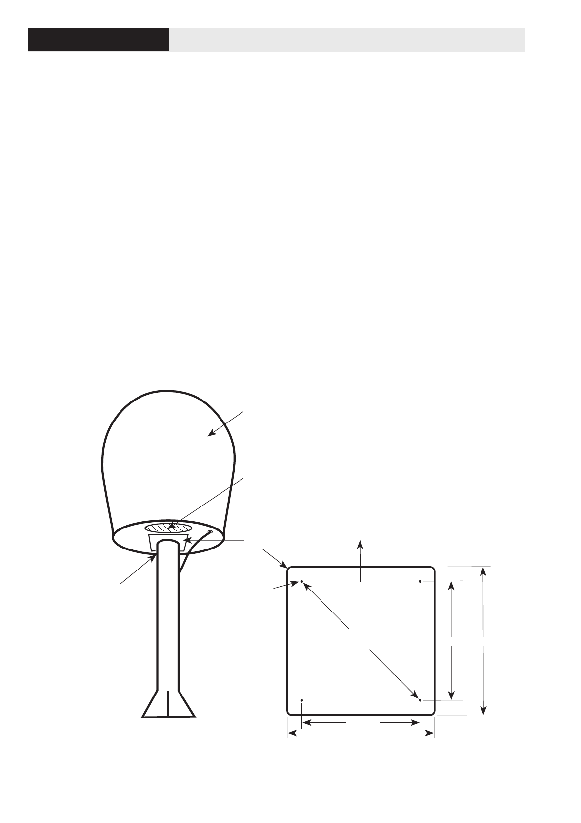
Designing the Antenna mast . . . . . . . . . . . . . . . . . . . . . . . . . 8
Outline dimensions of Antenna radome . . . . . . . . . . . . . . . . . 9
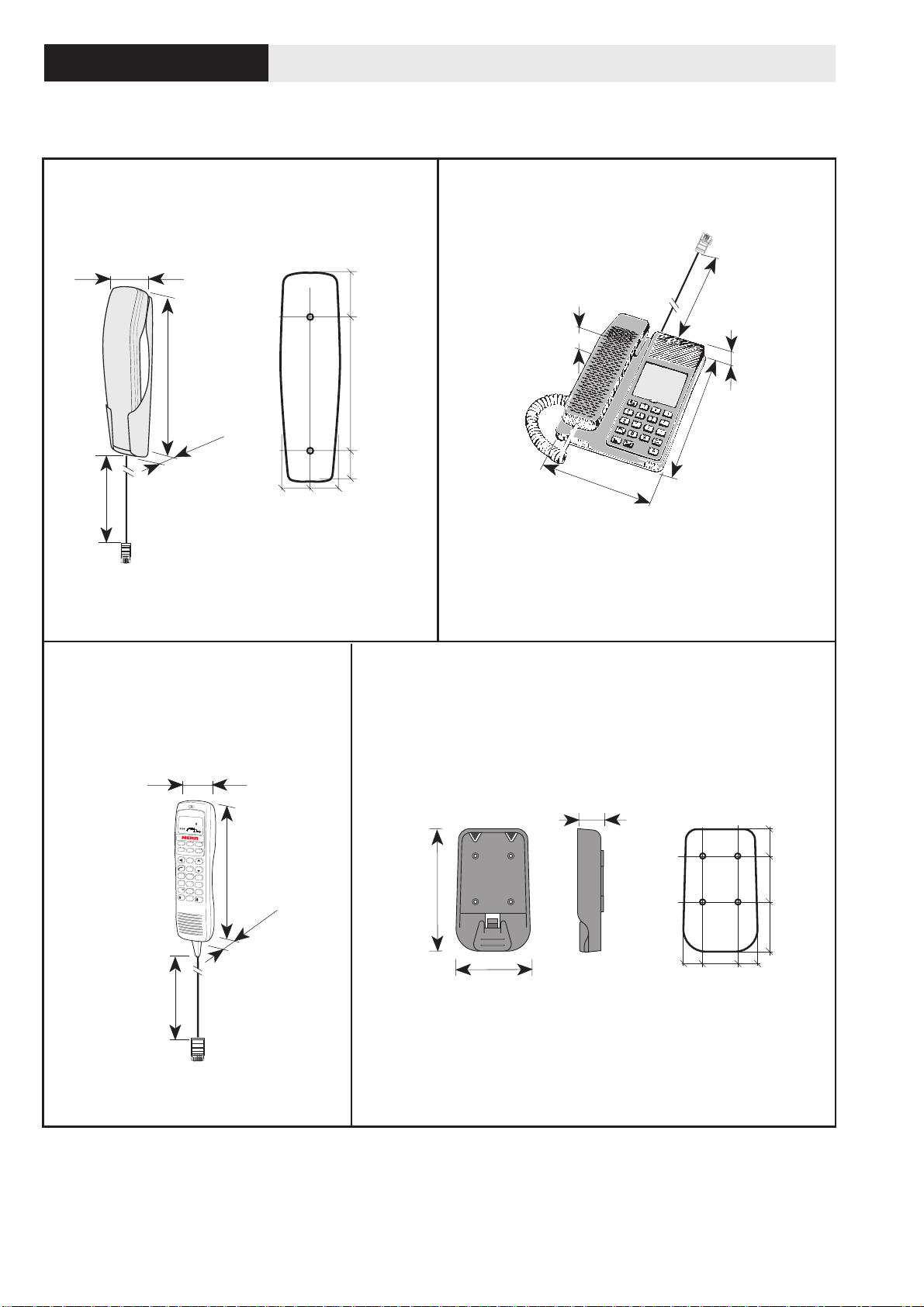
Physical characteristics of main units . . . . . . . . . . . . . . . . . 10
Example of BDE Installation . . . . . . . . . . . . . . . . . . . . . . . . 13
Example of Saturn Bm installation . . . . . . . . . . . . . . . . . . . . 14
Placing the Main Control Unit (MCU) . . . . . . . . . . . . . . . . . . 15
Placing the Distress Alarm and the Message Indicator . . . . 15
Placing the telephone(s) . . . . . . . . . . . . . . . . . . . . . . . . . . . 15
Placing the telefax (option) . . . . . . . . . . . . . . . . . . . . . . . . . 16
Placing the PC & Printer (telex, option) . . . . . . . . . . . . . . . . 16
Placing the DTE Equipment . . . . . . . . . . . . . . . . . . . . . . . . . 16
Requirements relating to GMDSS power supply . . . . . . . . . 16
Groundingconsiderations . . . . . . . . . . . . . . . . . . . . . . . . . . 17
Recommended location of units . . . . . . . . . . . . . . . . . . . . . 18
Layingcables . . . . . . . . . . . . . . . . . . . . . . . . . . . . . . . . . . . . 19
Unpacking . . . . . . . . . . . . . . . . . . . . . . . . . . . . . . . . . . . . . . 20
Installing the Above Decks Equipment (ADE) . . . . . . . . . . . 20
Mounting the Main Control Unit (MCU) . . . . . . . . . . . . . . . . 21
DisplayHandset . . . . . . . . . . . . . . . . . . . . . . . . . . . . . . . . . 22
Handsetcradle/holder . . . . . . . . . . . . . . . . . . . . . . . . . . . . . 22
ADE – Connecting the coaxial cable to the Antenna . . . . . . 23
BDE – Connecting the coaxial cable to the MCU . . . . . . . . . 23
Telephones . . . . . . . . . . . . . . . . . . . . . . . . . . . . . . . . . . . . . 24
Telephone and/or telefax socket (option) . . . . . . . . . . . . . . . 24
Gyro . . . . . . . . . . . . . . . . . . . . . . . . . . . . . . . . . . . . . . . . . . 25
NMEA-0183 input sources . . . . . . . . . . . . . . . . . . . . . . . . . . 26
PC (telex) . . . . . . . . . . . . . . . . . . . . . . . . . . . . . . . . . . . . . . 26
Printer . . . . . . . . . . . . . . . . . . . . . . . . . . . . . . . . . . . . . . . . . 27
PC (data) . . . . . . . . . . . . . . . . . . . . . . . . . . . . . . . . . . . . . . . 27
Distress Alarm Unit . . . . . . . . . . . . . . . . . . . . . . . . . . . . . . . 28
Message Indicator Unit . . . . . . . . . . . . . . . . . . . . . . . . . . . . 29
Example of local or near-by installation . . . . . . . . . . . . . . . . 30
Example of remote installation . . . . . . . . . . . . . . . . . . . . . . . 31
Interconnection diagrams for termination/connection boxes 32
Location and grounding of units, example 1 . . . . . . . . . . . . 33
Location and grounding of units, example 2 . . . . . . . . . . . . 34
Location and grounding of units, example 3 . . . . . . . . . . . . 35
Connecting up Below Decks Equipment . . . . . . . . . . . . . . . 36
Connecting up Above Decks Equipment . . . . . . . . . . . . . . . 37
Power Supply connected to MCU . . . . . . . . . . . . . . . . . . . . 38
Power Supply connected to telex and printer . . . . . . . . . . . . 39
Mounting connector type 11N-50-10-4 . . . . . . . . . . . . . . . . . 40
Mounting connector type 11N-50-12-10 . . . . . . . . . . . . . . . . 41
Mounting connector type 11N-50-23-10 . . . . . . . . . . . . . . . . 42
Mounting connector type 11N-50-32-2/11N-50-42-2 . . . . . . 43
Main items . . . . . . . . . . . . . . . . . . . . . . . . . . . . . . . . . . . . . . 44
9 pin-to-25 pin RS 232 cable . . . . . . . . . . . . . . . . . . . . . . . . 46
9 pin-to-9 pin RS 232 cable . . . . . . . . . . . . . . . . . . . . . . . . . 46
Centronics cable . . . . . . . . . . . . . . . . . . . . . . . . . . . . . . . . . 46
Printer switch settings . . . . . . . . . . . . . . . . . . . . . . . . . . . . . 47
Reception of L-band Broadcast signals . . . . . . . . . . . . . . . . 48
Activation of "Radio Silence" . . . . . . . . . . . . . . . . . . . . . . . . 49
Rotary Joint mounting instruction . . . . . . . . . . . . . . . . . . . . . 50
Azimuth angle map . . . . . . . . . . . . . . . . . . . . . . . . . . . . . . . 54
Elevation angle map . . . . . . . . . . . . . . . . . . . . . . . . . . . . . . 54
Doc. No. QLZB911053 Rev. G Nera Satcom AS 11/02
SYSTEM
PLANNING
APPENDIX 1 – 4
POWER SUPPLY
APPENDIX 5
APPENDIX 6
APPENDIX 7
APPENDIX 8
APPENDIX 9
APPENDIX 10
APPENDIX 11
INSTALLATION