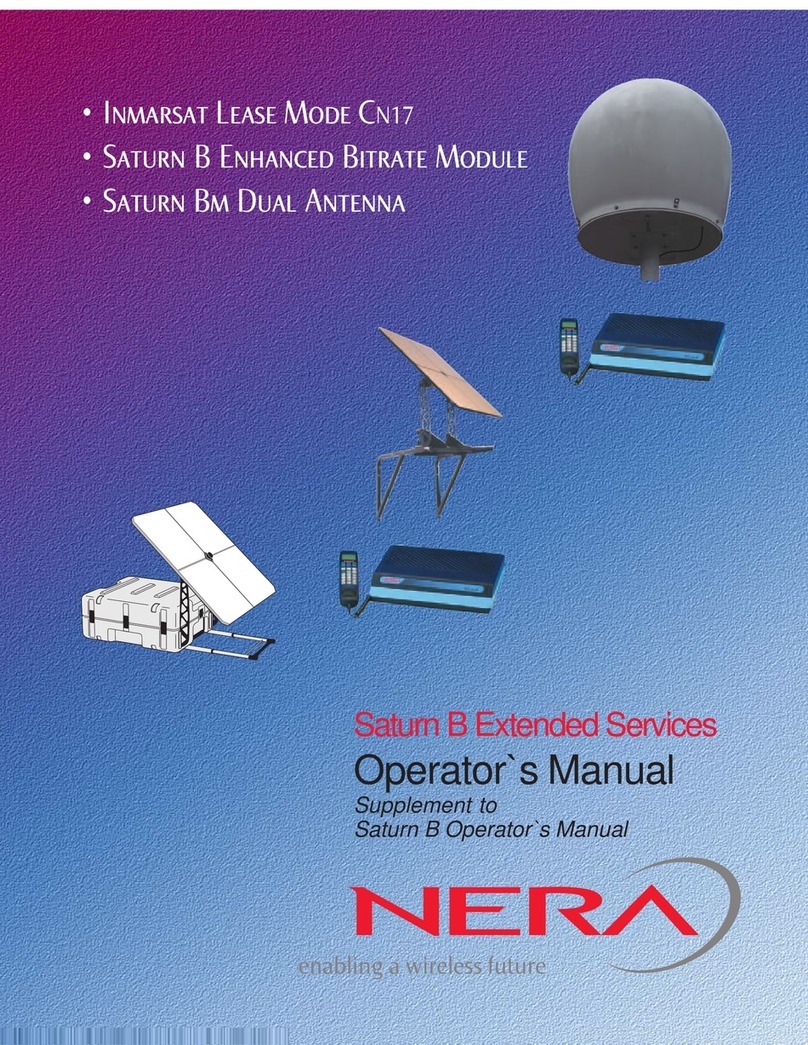
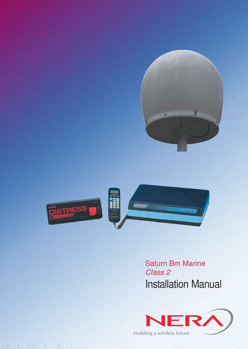
Nera Saturn Bm Marine Mk2 User manual

Inmarsat B
Das Inmarsat B benötigt eine grosse Satellitenantenne und kommt
deshalb auf Segelbooten nicht zum Einsatz.
In der LRC (Long Range Certificate) Prüfung werden einige
systemvergleiche Fragen zu Inmarsat B und Inmarsat M gestellt.
Beide stellen wie im Telefonnetz eine Verbindung zwischen den
Teilnehmern her, das Inmarsat C arbeitet dagegen nach dem Store
and Foreward Prinzip – ähnlich wie der email Transport im
Internet.
SatBm_Technical_Manual_S2.pdf
http://funk-an-bord.de/downloads.html
-- 1 of 30
LRC Prüfung

Saturn Bm Marine Mk2
Technical Manual
-- 2 of 30
LRC Prüfung

-- 3 of 30
LRC Prüfung

1Saturn Bm Mk2 Marine – Technical Manual
Contents
Introduction
Introduction
Saturn Bm Mk2 Marine – Onboard the Ship.................................................. 2
Saturn Bm Mk2 Marine – Main Parts............................................................. 3
Technical Data............................................................................................... 4
MCU Connector Panel................................................................................... 5
The INMARSAT-B System............................................................................. 6
System Description
System Description
Saturn Bm Marine Communication................................................................ 8
Signalling & Communication Channels ........................................................11
Communication Sequences......................................................................... 12
Idle State ..................................................................................................... 14
SCPC Signalling.......................................................................................... 16
Voice............................................................................................................ 18
Clearing ....................................................................................................... 20
Diagrams
Diagrams
Block Diagram ............................................................................................. 23
MCU Interconnection Diagram .................................................................... 24
Antenna Unit Interconnection Diagram........................................................ 26
Antenna Pedestal Interconnection Diagram................................................ 27
Service
ServiceService
MCU – Parts Identification........................................................................... 28
Replacing MCU Parts .................................................................................. 29
Saturn BmAntenna Parts Identification....................................................... 33
Pedestal....................................................................................................... 34
List of Spare Parts....................................................................................... 35
Service Level Functions .............................................................................. 36
List ofAlarm Messages ............................................................................... 37
List of Start-up Messages............................................................................ 39
List of Terminal Status Messages................................................................ 39
List of Clear Causes .................................................................................... 40
List of Terms ................................................................................................ 43
Doc. No. QLZB911022 Rev. C Copytema 3/98
Nera SatCom AS reserves the right to change the design
and specifications of the equipment without notice.
-- 4 of 30
LRC Prüfung
Aus dem Handbuch entfernt

2Saturn Bm Mk2 Marine – Technical Manual
Introduction
IntroductionIntroduction
BDE
Below Deck Equipment
The Saturn Bm Main Control Unit (MCU)
can be placed in any suitable location, but is
usually installed in the radio room.
The MCU is designed for wall or desk top
installation.
As all commands of the Saturn Bm terminal
may be carried out from the Display Handset,
the MCU can be located out of the way so as
not to occupy valuable working space.
The telephone(s) can be placed anywhere
onboard the vessel.
The following optional peripherals may be
connected to Saturn Bm:
• DTMF telephones (max 5)
• Telefax (for connection to a telephone port)
• Message Indicator
• PC (telex)
• PC (data)
• Serial printer
• GPS navigator
• Plug for NMEA-0183 connection
• Course gyro
• Power 11 - 34 VDC
• Power 110/220 VAC and 24 VDC
(automatic switchover)
S
a
t
u
r
n
B
ADE
Above Deck Equipment
The Saturn Bm Mk2 Above Deck Equipment (ADE) is protected by a
radome, and it is mounted on a mast to avoid possible obstructions.
Obstructions will cause blind spots, with the result of signal degradation
or even loss of communication with the satellite.
The ADE should also be separated as far as possible from the HF
antenna, and preferably by at least 5 m from the antennas of other
communication or navigation equipment.
Neither must the ADE be placed behind the funnel, as smoke deposits
then evenually will degrade the antenna performance.
Saturn Bm Mk2 Marine – Onboard the Ship
FUN
LP
NT R
H FT
EL
E
T
T
Ø
4
K
1
A
L S
L ST
3
GH
6
P
9
Y
S
N/F
DEL
2
5
MN
8
V
Ä
DIAL 00+INTL
TEL NO +
I T
Saturn B
-- 5 of 30
LRC Prüfung

3Saturn Bm Mk2 Marine – Technical Manual
ADE
BDE
Introduction
Introduct onIntroduction Saturn Bm Mk2 Marine – Main Parts
Radome
Antenna
Dish
Antenna
Control
Unit
RF-Unit
Access
Hatch
Servo
Stabilized
Pedestal
Main Parts List, BDE
Below Deck Equipment NERA Part No.
Main Control Unit, MCU QUFC 911 901-2
Display Handset QDGS 911 903
Distress Alarm QUFC 911 910-2
Interface box QUFC 911 918
Main Control Unit, MCU NERA Part No.
Main Control Board QROF 219 9001-2
Power Board QROF 219 9002
Connection Board QROF 219 9005
Gyro Board QROF 219 9003
Power Supply 220/110V QDFC 911 903-2
Options NERA Part No.
Telephone (wall) DBAR 104 001/888
Telephone (desk) DBAR 104 001/888
Message Indicator QUFC 911 910-3
Power Supply for battery backup
QUFC 911 920
Screened cable w/ferrite core
QRPM 911 077/1000
Telefax Adapter QRPM 911032
For further information, see the Saturn Bm Installation Manual.
Display
handset Main Control Unit – MCU
Gyro
interface
1
3
D L
8
DIAL 00+ NTL
TEL NO
O
FT
Basic Equipment
Optional Equipment
Telephones
(wall or desk)
Distress Alarm Power Supply
PC (Data)
Message
Indicator
Mes age I dic tor
SA URN B
SGE
ELEXM SSGE
FAMES
REET
Power Supply
(Battery backup of
MCU,PC and Printer)
PC (Telex) Printer
Telefax
(replacing a
telephone)
DISTRESS
Saturn B
A ARM
ACKNOWLEDGE
Main Parts List, ADE
Above Deck Equipment NERA Part No.
Stabilized Platform, AU QSXK 911 951
Radome (R 906 565) QSXK 911 903
RF Unit QUFC 911 931
Antenna Control Unit, ACU:
• Antenna Control Board, ACB QROF 2199041
• Pedestal Control Unit, PCU MM 113 101
Reflector Antenna (10AY652A) SXAR 920 210
Antenna Feed QSXK 911 906
-- 6 of 30
LRC Prüfung

4Saturn Bm Mk2 Marine – Technical Manual
Services
Voice: 16 kbps
Telefax: 9.6 kbps
Telex: 50 Baud (Class 1 only)
Asynchronous Data: 9.6 kbps
High Speed Data: 56/64 kbps full duplex
(option)
System Specifications
Radio frequency performance
Transmit Frequencies: 1626.5 - 1646.5 MHz
EIRP: 33/25 dBW
Receive Frequencies: 1530.0 -1559.0 MHz
Channel spacing: 20 kHz
G/T: -4 dB/K
Antenna Unit
1 m stabilized parabolic dish
Gain: 21.8 dB Tx, 21.1 dB Rx
Axial ratio less than 2 dB on axis
Polarisation: right-hand circular (CCIR 573)
Steerability: hemispheric coverage, 0°- 90°
Tracking: Automatic search.
Cable rewind: 30 seconds
Ship Motion
Max turning rate: 12°/sec
Roll: ±30°
Pitch: ±10°
Yaw: ±8°
Physical Characteristics
Above Deck Equipment (ADE)
Size: H = 1445 mm, D = 1420 mm,
see drawing
Weight: 90 kg
Mounting: Flange
Main Control Unit (MCU)
Size: 310 x 236 x 70 mm,
see drawing
Weight: 4 kg
Mounting: Special mounting bracket,
see Installation Manual
Technical Data Introduction
IntroductionIntroduction
Environmental Conditions
Vibration, Precipitation and Icing: As specified by Inmarsat
Above Deck Equipment
Temperature: -25°C to 55°C
Rain: 100 mm/hour
Below Deck Equipment
Temperature: -25°C to 55°C
Humidity: 95 % at 40°C
Electromagnetic Compatibility
Radiated: EN55022 class B
Conducted: EC 801
Cabling
ADE - BDEU: Length up to 44 m: single, flexible, 20 mm
diameter
Length to 44-77 m: One coaxial 06230
10.3 diameter (Ethernet) and one screened
mains cable.
Telephone/telefax: screened twisted pair
Auxiliary : 8-core cable
Display Handset : 8-core cable
PC : RS-232 cable
Printer : RS-232 cable
Distress Alarm : 4-core screened cable
Power requirements
Voltage: 11 - 34 VDC
Power Consumption: 150 W
Power Supply: 220 VAC to 28 VDC
Optional Power Supply:
220 VAC to 28 VDC with
24 VDC battery backup input
Interfaces
Telephone/telefax: 5 x RJ11, 2-wire with echo cancelling
and touch-tone dialing
Fax: CCITT G3 at 2400 bps
Data: D-sub, 25-pin female, 9600 bps,
RS-232, Hayes AT compatible
PC: D-sub, 9-pin female, RS-232
Printer: D-sub, 9-pin male, RS-232
Gyro: Synchro, step-by-step, 1:360, 1:180, 1 :90
Navigator: NMEA-0183
S
a
t
u
r
n
B
1445 mm
1200 mm
305 mm
350 mm
80 mm
Saturn B
-- 7 of 30
LRC Prüfung

5Saturn Bm Mk2 Marine – Technical Manual
MCU Connector Panel
Introduction
Introduct onIntroduction
5 4 3 2 1
9 8 7 6
25 24 23 22 21 20 19 18 17 16 15 14
13 12 11 10 9 8 7 6 5 4 3 2 1
1 2 3 4 5
6 7 8 9
(J1) (J2) (J3) (J4) (J5) (J13)
(J10)(J6) (P12) (J7)
(P11)
(J8) (P9)
5 4 3 2 1
9 8 7 6
OFF
+[11 - 34 VDC] -
ON
HANDSET
EXT I/O GYRO NMEA-0183 DTE
TEL.1 TEL.2 TEL.3 TEL.4 TEL.5
AUX
PC PRINTER
Saturn B
Connectors:
Auxiliary
Telephones 1–5
(or telefax)
Extensions
Telephone display handset
Gyro
Navigator NMEA-183
PC (control/telex)
PC printer
PC (data)
Antenna cable
Power
Power ON/OFF
Power indicator
-- 8 of 30
LRC Prüfung

6Saturn Bm Mk2 Marine – Technical Manual
The INMARSAT-B System System Description
System DescriptionSystem Description
Figure 1.
Overview of the Inmarsat-B system.
Figure 2.
Four satellites in a geostationary orbit above the
equator at approx. 35700 km altitude.
LES
NCS
MES
TELEPHONE
NETWORKS
NCS: Network Coordinating Station
LES: Land Earth Station
MES: Mobile Earth station
(Saturn B terminal)
MES
DATA
NETWORKS
TELEX
NETWORKS
E
Q
U
A
T
O
R
EARTH
12000 km
35700 km
Pacific Ocean Region
Indian Ocean Region
54°W
64.5°E
178°E
15.5°W
Atlantic Ocean Region (West)
Atlantic Ocean Region (East)
Inmarsat
The INMARSAT-B system offers high quality 16 kbps
voice communication, and 9.6 kbps telefax and data
transmission.
The benefit of the INMARSAT system is its high
capacity, and the rapid and reliable connection
between the land based (fixed) users and the Mobile
Earth Stations (MESs).
The large number of Land Earth Stations (LESs) in
operation allows the operator to select the one giving
the lowest cost to a particular land based subscriber.
Each satellite region is under the control of a Net-
work Coordinating Station (NCS), which controls
and monitors the traffic between the MESs and the
LESs.
See figure 1.
Services
• Duplex telephone calls – basic telephony services
• Simplex telephone calls – LES-to-mobile only
• Duplex telefax – CCITT Group 3 facsimile servic-
es, 9.6 kbps
• Simplex telefax calls – LES-to-mobile only
• Simplex group ID addressing – to a selected
group of mobiles
• Simplex area addressing – to all mobiles within a
specific geographic area
• Duplex data communication – Hayes compatible
9.6 kbps data service
System Satellites
The satellites are positioned in a geostationary orbit
above the equator at approximately 35700 km alti-
tude.
In geostationary orbit, each satellite moves at the
same rate as the earth, and so remains in the same
relative position to the earth, above equator, allowing
the antenna to have line-of-sight communication with
the satellite.
The Saturn Bm Marine can communicate via the four
satellites covering one Ocean Region each.
The positions of the system satellites are shown in
figure 2.
Transmission frequencies
The INMARSAT-B MESs operate in the following
frequency bands:
Calls from Saturn B terminals 1626.5 MHz — 1646.5 MHz
Calls to Saturn B terminals 1530.0 MHz — 1559.0 MHz
A large number of channels are available (20 kHz
channel separation), offering either 16 kbps voice
communication, or 9.6 kbps duplex data communica-
tion.
Duplex communication uses two channel frequen-
cies, one in each direction.
The LESs provide interface to the international
networks for telephony and data: PSTN (Public
Switched Telephone Networks) and PSDN (Packet
Switched Data Networks).
-- 9 of 30
LRC Prüfung

7Saturn Bm Mk2 Marine – Technical Manual
System Description
System DescriptionSystem Description The INMARSAT-B System Cont’d
Figure 3.
Communication path.
Saturn Bm
Marine Land Earth
Station
LES
Display
Handset
Path established by
Saturn Bm terminal
via satellite
Telephone(s)
Local PABX
Telefax
Telex
Data/modem communication (option)
Saturn B
2
0
D AL 0+ L
EL NO
Public
Data
Network
Telefax
Public
Telephone
Network
PC/
modem
Public
Telex
Network
Channel numbers
All radio frequency channels used by the MES are
assigned a particular hexadecimal number which is
translated into frequencies on L-band between MES
and satellite, and to C-band between LES and satel-
lite.
Channel no. 32C8 for an MES always designates:
1660.5000 MHz transmitting frequency
1542.5000 receiving frequency
Channel Types
The Inmarsat-B System differs between physical and
functional channels. A physical channel refers to one
frequency, one carrier. Every frequency can have
several functional channels muliplexed on it. Each
functional channel is named after the originating unit.
The NCS TDM will in the initial system multiplex the
NCSC for Bulletin Boards and Call Announcement,
the NCSA for Channel Assignments and NCSI for
Interstation information to the LES on the same
physical channel. When the system expands, spot
beams and Ocean Region Registration will be intro-
duced using the functional channels NCSS and
NCRA multiplexed on the NCS TDM. The traffic on
one TDM may then be to heavy and some of the
functional channels may be moved to another NCS
TDM frequency.
The physical SCPC channels are always divided into
three functional channels. During call set up and
release the whole bandwith is used for signalling and
the functional channel is called MES-SIG/LES-SIG.
During speech or data phase, the signalling part of
the channel is called VSUB or DSUB and the service
carrying part is called MESV/LESV or MESD/LESD.
Requests and assignments
The Network Coordinating Station in each Ocean
Region continually transmits to the MESs within its
region on the NCS Common Signalling Channel
(NCSC).
When selecting a particular Ocean Region, the MES
automatically tunes its receiver to the NCSC fre-
quency, and awaits System Information from the
NCS.
The System Information (Bulletin Board) includes
available NCS/LES channel frequencies, location of
satellites, operational status, etc.
When the NCS sends a Call Announcement, detail-
ing the channel to which the MES should tune to
receive the call.
When the MES user dials a subscriber’s international
telephone number, the MES transmits an Access
Request to the NCS via the LES, and awaits a Chan-
nel Assignment from the NCS.
Telephone communication
For telephone communication a Frequency Division
Multiple Access (FDMA) is used, in a Single Channel
Per Carrier (SCPC) system. The voice communica-
tion occupies two (unpaired) channel frequencies.
The telephone channels are controlled by NCS which
assigns a free channel upon request. When a chan-
nel has been assigned it is controlled by LES until
end of call.
Facsimile communication
The Saturn Bm telephone ports may be configured
for telefax communication. The transmission is
telefax only, and is performed at a rate of 9.6 kbps.
Telefaxes without keypad may be connected via an
adapter.
Data communication
The data service allows the Saturn Bm user to com-
municate at up to 56/64 kbps, via the public switched
network, to fixed modems and data terminals.
-- 10 of 30
LRC Prüfung

8Saturn Bm Mk2 Marine – Technical Manual
Saturn Bm Marine Communication System Description
System DescriptionSystem Description
Calls from Mobiles
To initiate a call, the user dials the international call prefix
00 prior to the telephone number for the required destina-
tion. The LES code is also included, either automatically
when using the default LES, or manually selected from the
Display Handset.
The mobile automatically includes information to identify
the MES and the particular end terminal that originates the
call. Saturn Bm has six connections: the Display Handset
and five connectors that are normally configured for tele-
phone and a telefax.
The LES uses the end terminal identifying information (OI)
for billing purposes.
The mobile transmits the dialing information on a channel
specially assigned by the NCS, to the LES, which also has
been instructed to tune to the same channel.
On receiving the call, LES routes it over the public tele-
communications networks to the intended destination.
When the destination responds, for example by the dialed
subscriber lifting the handset, the call proceeds.
The illustration of the call initiation is simplified.
PSTN
00 47 66 84 47 00
Calls from Mobiles
Forward/return ID
123456/ABCDEF
OI
1
Type
Voice
Commissioned
Yes
66 84 47 00
LES Translation Table
MES Translation Table
When the MES originates a call it starts
by sending a request to the LES.
This initial request for service contains
the MES Return ID and type of service.
Saturn Bm incorporates a configuration
table for originating information,
accessible through the “Configure Ports”
function (70). This table contains one
entry for every physical connector with
the Originating Id and type of service for
that specific connector.
LES
Return ID
Type
2
ABCDEF
Voice
Access Request
Fwd ID
Rx ch.
Tx ch.
123456
8192
12000
Channel assignment
S
a
t
u
r
n
B
T
T L NO
Connector
Service/
Originating Id
Phone/OI=1
Phone/OI=2
Fax/OI=17
Default=no OI
Default=no OI
Default=no OI
Telex/OI=49
HANDSET
TEL.1
TEL.2
TEL.3
TEL.4
TEL.5
PC
LES=2
S
Sa urn B
NERA
-- 11 of 30
LRC Prüfung

9Saturn Bm Mk2 Marine – Technical Manual
System Description
System DescriptionSystem Description Saturn Bm Marine Communication Cont’d
Calls to Mobiles
Calls are made as ordinary international (Satellite) calls
where each Ocean Region has an international country
code. If an area is covered by more than one satellite, it is
necessary that the caller knows which satellite (Ocean
Region) the mobile is tuned to.
The international codes to the four Ocean Regions are as
follows:
Atlantic Ocean East Region: 871
Pacific Ocean Region: 872
Indian Ocean Region: 873
Atlantic Ocean West Region: 874
The illustration of the call initiation is simplified.
S
DI
1
2
17
Telephone
Ring on handset
Calls to Mobiles
00 871 681234567
Telephone
Ring on TEL.1
Facsimile
Ring on TEL.2
Incoming
call route
MES Translation Table
TEL.3 No DI
TEL.4 No DI
TEL.5 No DI
When requested to call a specific IMN, LES translates
the IMN to a Forward ID and a Destination Id (DI).
The request is then sent to the MES which translates
the Forward ID and the DI to a physical line to call.
To "connect" a Destination Id to a physical line,
Saturn Bm incorporates a translation table accessible
through the “Incoming call route” function (71). This table
can contain up to 100 DI translations, and each DI in
use is programmed with type of call and destination.
A call is not allowed to be routed to a connector that is
configured to another type than the DI specifies.
A telephone DI can only be routed to a phone type
connector. A facsimile DI can only be routed to a fax
type connector.
LES
Fwd ID
Type
DI
2
123456
Voice
1
Call announcement
S
a
t
u
r
n
B
PC 49
LES Translation Table
Forward/return ID
123456/ABCDEF
123456/ABCDEF
123456/ABCDEF
123456/ABCDEF
DI
01
02
17
49
Type
Voice
Voice
Fax
Telex
IMN
681234567
681234789
681234890
681234481
8
T L NO
LES=2
LES
Return ID
Type
2
ABCDEF
Voice
Response
Sat rn B
NERA
-- 12 of 30
LRC Prüfung

10 Saturn Bm Mk2 Marine – Technical Manual
System Description
System DescriptionSystem Description
-- 13 of 30
LRC Prüfung

11Saturn Bm Mk2 Marine – Technical Manual
NCS Common Ch (NCSC)
NCS Assignment Ch (NCSA)
NCS Registration (NCRA)
NCS Spot beam (NCSS)
MES
Saturn Bm
Marine
terminal.
MES Request Ch (MESRQ)
MES Region Registration Ch (MESRR)
MES Call Acknowledge Ch (MESCA)
SCPC In-band Signalling (MESSIG)
SCPC In-band Signalling (LESSIG)
SCPC Voice (MESV/VSUB)
SCPC Voice (LESV/VSUB)
SCPC Data (MESD/DSUB)
SCPC Data (LESD/DSUB)
LES
The Land Earth Station
routes messages to/from
the MESs within the
coverage area of one of
the four Inmarsat
satellites.
NCS/NCS
Signalling Links
NCS
The Network Coordinating
Station controls the satellite
resources to LESs and
MESs within a single
satellite coverage area.
MES Region Registration Ch (MESRR)
MES Response Ch (MESRP)
MES Request Ch (MESRQ)
NCS Interstation Ch (NCSI)
LES Interstation Ch (LESI)
(SCPC = Single Channel Per Carrier)
Public Switched
Telephone
Networks
ISDN
Packet Switched
Data Networks
1
4
T L NO
S
a
t
u
r
n
B
Sa urn B
NERA
Communication Channels
Designation Transmission Type of information
LESV
MESV
LESD
MESD
SCPC with Duplex 16 kbps voice
VSUB sub-band communication
signalling
SCPC with Duplex 9.6 kbps data
VSUB sub-band communication
signalling
Signalling Channels
Designation Transmission Type of information
NCSI
LESI
NCSC
MESRP
NCSA
MESRQ
MESCA
NCSS
MESRR
NCRA
MESSIG
LESSIG
Continuous TDM Bi-directional signalling information
between LES and NCS
TDM Bulletin Board announcements.
TDMA MES responses
Continuous TDM Assigns SPCS channels
Slotted Aloha Request from MES to LES
Slotted Aloha Acknowledges shore-originated
simplex calls.
Continuous TDM One frequency per spot beam;
enables an MES to identify beam
serving location.
Slotted Aloha Registration signal to LES/NCS.
Continuous TDM Acknowledgement from NCS to
MES
SCPC In-band signalling
Signalling & Communication Channels
System Description
System DescriptionSystem Description
-- 14 of 30
LRC Prüfung

12 Saturn Bm Mk2 Marine – Technical Manual
Listens to NCS common
channel.
LES
Land Earth Station
NCS
Network
Coordination
Station
NCS Common Channel
OFF-HOOK
MES operator dials
subscriber’s international
telephone number.
Transmits "Access Request"
SU.
MES
Mobile Earth Station
MESRQ
Adds MES to NCS
busy list.
Transmits "Channel
Assignment" SU.
NCSA:
Once for maritime
MES. Three times for
Land mobile MES.
Adds MES to LES
busy list.
"Request for Channel
Assignment" SU
NCSI
NCSA
Sets SCPC channel in "In-
band Signalling" mode.
Transmits "Service Address"
SUs and "Scrambling Vector
Advice" SU alternately.
MES-SIG
Returns "Scrambling
Vector Acknowledge"
SU.
LES-SIG
MES-SIG
Changes to
LESV/SUB mode.
"Return Carrier Identifier"
SUs
Changes to MESV/SUB
mode
Transmits "Ringing
Tone" & "Fill-in" SUs.
"Ringing tones"
Sends answer signal
& "LES Connect" SUs.
"Fill-in" SUs when
quiet.
Maintains burst SU
every 5 secs to
prevent clearing by
MES.
Transmits "MES
Connect" SUs.
Transmits speech
and "MES Connect"
SUs continuously.
LESV & SUB
SUB
LES Voice Channel
and sub-band
signalling
LESI
SUB
Terrestrial call set-up
procedure.
For call release, see
separate diagram
SUB
INMARSAT-B
MES-originated Duplex Telephone Call
Set-up
SCPC In-band Signalling Mode
SCPC Voice Mode
✳
S
a
t
u
r
n
B
Set-up
SCPC In-band Signalling
SCPC Voice Mode
Listens to NCS common
channel.
NCS Common Channel
MES number from
telephone network.
Validates MES
authorization.
Adds MES to LES
busy list. "Request
for Call
Announcement" SU.
NCSI
NCSA
Sets SCPC channel in "In-
band Signalling" mode.
Transmits "Scrambling
Vector Advice" SU
repeatedly.
MES-SIG
Returns
"Scrambling Vector
Acknowledge" SUs
repeatedly.
LES-SIG
RINGING
LESI
NCSC
Ringing tone
(generated by LES)
MES-SIG
Transmits "Return Carrier
Identifier" SUs.
Switches to MESV/SUB
mode
Transmits "Channel
Assignment" SU.
NSCA: Once for
maritime MES. Three
times for Land mobile
MES.
MESRP
Transmits "MES
Response" SU on the
TDMA channel.
Adds MES to NCS
busy list.
"Call Announcement"
SU. Repeated once if
no response from
Land Mobile MES.
MES
Mobile Earth Station
LES
Land Earth Station
NCS
Network
Coordination
Station
OFF-HOOK
Transmits "Connect" SUs
For call release, see
separate diagram
"Fill-in" SUs when
quiet.
Maintains burst SU
every 5 secs to
prevent clearing by
LES.
Transmits speech
and "MES Connect"
SUs continuously.
SUB
SUB
INMARSAT-B
Fixed-originated Duplex Telephone Call
✳
✳
S
a
t
u
r
n
B
System Description
System DescriptionSystem DescriptionCommunication Sequences
-- 15 of 30
LRC Prüfung

13Saturn Bm Mk2 Marine – Technical Manual
System Description
System DescriptionSystem Description Communication Sequences Cont’d
LES
Land Earth Station
NCS
Network
Coordination
Station
MES
Mobile Earth Station
Switches to "In-band
signalling" mode and
sends channel
release SUs.
(Delay up to 2 min if
called party)
Terrestrial side
ON-HOOK
ON-HOOK.
MES switches to "In-band
signalling" mode and sends
6 frames of "Channel
Release" SUs,
then turns off carrier.
MES-SIG
Clear forward.
Observes MES carrier
off, then turns off LES
carrier and sends
"Notification of
Channel Release" SU
to NCS.
Removes MES from
LES busy list.
LESI
Removes MES from
NCS busy list, and
updates channel
status table.
LES-SIG
LESI
Removes MES from
NCS busy list, and
updates channel
status table.
ON-HOOK.
MES switches to "In-band
signalling" mode and
sends 6 frames of channel
release SUs,
then turns carrier off.
MES-SIG
Observes MES carrier
off, then turns off LES
carrier and sends
"Notification of
Channel Release" SU
to NCS.
Removes MES from
LES busy list.
INMARSAT-B
MES or Fixed Call Release
Voice Mode
Signalling Mode
Voice Mode
Signalling Mode
✳
S
a
t
u
r
n
B
-- 16 of 30
LRC Prüfung

14 Saturn Bm Mk2 Marine – Technical Manual
BDE
Idle State System Description
System DescriptionSystem Description
MAIN CONTROL BOARD
Digital Signal Processor Sub-system
Telephony
Interface Computer
Codec
RXIF
12 MHz
Transmitter
Combiner/
splitter
Local
Oscillator
Synthesizer
Receiver
RF Sub-system
RX Channel
1530 -
1559 MHz
TXIF
2.5 MHz
TX Channel
1626.5 -
1646.5 MHz
U
L HA
HF
MR
ET
E
7
S
Å
J
B
L T
3
6
PQ
9
YZ
P
O F
DE
2
D
5
M
8
VX
0
D AL 00+INTL
TEL NO +
O
-- 17 of 30
LRC Prüfung

15Saturn Bm Mk2 Marine – Technical Manual
NCS Common Channel (NCSC)
ADE
shift shift
shiftshift
shift
t
BPSK Encoded Signal
(BPSK = Binary Phase Shift Keying)
Forward Direction
MES NCS
System Description
System DescriptionSystem Description Idle State
MULTI
FRAME
TIMESLOT
7
FRAMING
BITS
32
RATE - 1/2 FEC CODED BITSTREAM
1552 bits
FRAMING
BITS
32
RATE - 1/2 FEC CODED BITSTREAM
1552 bits
Approx. 264 ms
FRAMING
BITS
32 RATE - 1/2 FEC CODED BITSTREAM
1552 bits
8 bits96 bits
TIMESLOT
6
96 bits
TIMESLOT
5
96 bits
TIMESLOT
4
96 bits
TIMESLOT
3
96 bits
TIMESLOT
2
96 bits
TIMESLOT
1
96 bits
TIMESLOT
0
96 bits
OCTET No.
1
2
3
4
5
6
7
8
9
10
11
12
8 7 6 5 4 3 2 1
BIT No.
SIGNALLING UNIT – SU
CCITT CRC
(CYCLIC REDUNDENCY CHECK)
MES ID LES ID
SPARE
PRIORITY
SPARE
CHANNEL
PARAMETERS
MESSAGE
TYPE
Octet No. 1 Octet No. 2 Octet No. 3 Octet No. 4 Octet No. 5 Octet No. 6 Octet No. 7 Octet No. 8 Octet No. 9 Octet No. 10 Octet No. 11 Octet No. 12
SIGNALLING UNIT = 12 "OCTETS" = 96 BITS
EXAMPLE: CALL ANNOUNCEMENT (TYPE 81
H
)
81H
SERVICE
NATURE
SRVICE
TYPE
ECHDDH18H09H00H01H01H
DESTINATION
TERMINAL ID
01H
SPARE
MESSAGE
NUMBER
00H54H26H
100000011110110011011101000110000000100100000000000000010000000100000001000000000101010000100110
Message type
MES ID
LES ID
channel parameters
destination terminal ID
CCITT CRC
priorityspare spare
service nature service type
spare message number
81
M1
CALLANNOUNCEMENT
Duplexer
RF Unit
HPA
Combiner/splitter
LNA
Stable Platform
Right Hand Circular
polarized RF signal
f = 1530 - 1559 MHz
-- 18 of 30
LRC Prüfung

16 Saturn Bm Mk2 Marine – Technical Manual
BDE
SCPC Signalling System Description
System DescriptionSystem Description
MAIN CONTROL BOARD
Digital Signal Processor Sub-system
Telephony
Interface Computer
Codec
RXIF
12 MHz
Transmitter
Combiner/
splitter
Local
Oscillator
Synthesizer
Receiver
RF Sub-system
RX Channel
1530 -
1559 MHz
TXIF
2.5 MHz
TX Channel
1626.5 -
1646.5 MHz
U C
L H
NE
HF
HL
T
C
7
S
J
B
IT
LT
3
G
6
PQ
9
Y Æ
P
O O
E
D
5
M
8
V
0
ÄÖ
D AL 00+INTL
TEL NO +
-- 19 of 30
LRC Prüfung

17Saturn Bm Mk2 Marine – Technical Manual
O-QPSK Encoded Signal
(O-QPSK = Offset Quadrature Phase Shift Keying)
t
0°+90°+270°+180°0°+90°+270°+180°
SCPC Channel (Single Carrier Per Channel)
In-band Signalling Mode
Forward Direction
MES LES
ADE
* Unique Word:
0111 1000 1001
for 1st subframe, and
1000 0111 0110
for 2nd, 3rd and 4th
subframe (compliment)
DUMMY
CW
24 bits
SUB
32 bits SU1
60 ms
* UW
24 bits
FLUSH
8
bits
FLUSH
DUMMY
6 bits
Before FEC
coding
6 bits
SU1SU1
96 BIT
SIGNALLING UNIT
384 bits
8
bits
SU
SUBFRAME - 4
SU
SUBFRAME - 3
SU
SUBFRAME - 2
SU
SUBFRAME - 1
60 ms 60 ms 60 ms 60 ms
n x 240 ms
END OF
DATA
192 bits
CONTIN.
WAVE
96 bits
BIT
TIMING
64 bits IN-BAND SIGNALLING FRAME
1920 bits IN-BAND SIGNALLING FRAME
1920 bits
240 ms240 ms 24 ms
OCTET No.
1
2
3
4
5
6
7
8
9
10
11
12
8 7 6 5 4 3 2 1
BIT No.
SIGNALLING UNIT – SU
CCITT CRC
(CYCLIC REDUNDENCY CHECK)
SPARE
(Random binary bits)
MES IDMESSAGE
TYPE
Octet No. 1 Octet No. 2 Octet No. 3 Octet No. 4 Octet No. 5 Octet No. 6 Octet No. 7 Octet No. 8 Octet No. 9 Octet No. 10 Octet No. 11 Octet No. 12
SIGNAL UNITS = 12 "OCTETS" = 96 BIT SIGNALLING UNIT.
EXAMPLE: SCRAMBLING VECTOR ACKNOWLEDGE
95
H
4A
H
09
H
EC
H
DD
H
18
H
09
H
F1
H
BC
H
06
H
79
H
D5
H
LES ID
LES_SIG
SIGNALLING
CHANNEL
100101011110110011011101000110000000100111110001101111000000011001111001110101010100101000001001
Message type
MES ID
LES ID
CCITT CRC
spare
95
M21
SCRAMBLING VECTOR ACKNOWLEDGE
System Description
System DescriptionSystem Description SCPC Signalling
Duplexer
RF Unit
HPA
Combiner/splitter
LNA
Stable Platform
Right Hand Circular
polarized RF signal
f = 1530 - 1559 MHz
-- 20 of 30
LRC Prüfung
Table of contents
Other Nera Antenna manuals

Nera
Nera F77 User manual

Nera
Nera Saturn Bt User manual

Nera
Nera Saturn B User manual

Nera
Nera Saturn B User manual

Nera
Nera Saturn BM Marine User manual

Nera
Nera WorldCommunicator User manual

Nera
Nera WorldCommunicator User manual

Nera
Nera SatLink 1000 User manual

Nera
Nera WorldPro1000 User manual

Nera
Nera F77 User manual
Popular Antenna manuals by other brands

Televes
Televes DATBOSSMIX 149484 quick start guide

Thrane&Thrane
Thrane&Thrane SAILOR TT-3084A Fleet 77 user manual

Channel Master
Channel Master ULTRA-HI CROSSFIRE CM-3671 instruction sheet

Hawking
Hawking Hi-Gain HAO14MD Quick installation guide

Antennas4Less
Antennas4Less SignaLoop HF-319 manual

Maximum
Maximum DA-6000 manual