nest Dakota High Sleeper MG 7507 User manual

TOP TIPS BEFORE YOU START ! IMPORTANT. READ CAREFULLY - RETAIN FOR FUTURE REFERENCE
1 ' Please check that all parts & hardware are present before you start the assembly of your furniture.
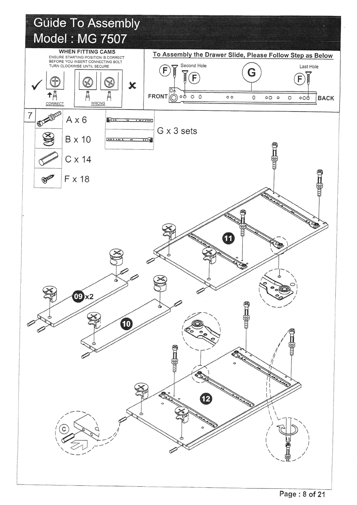
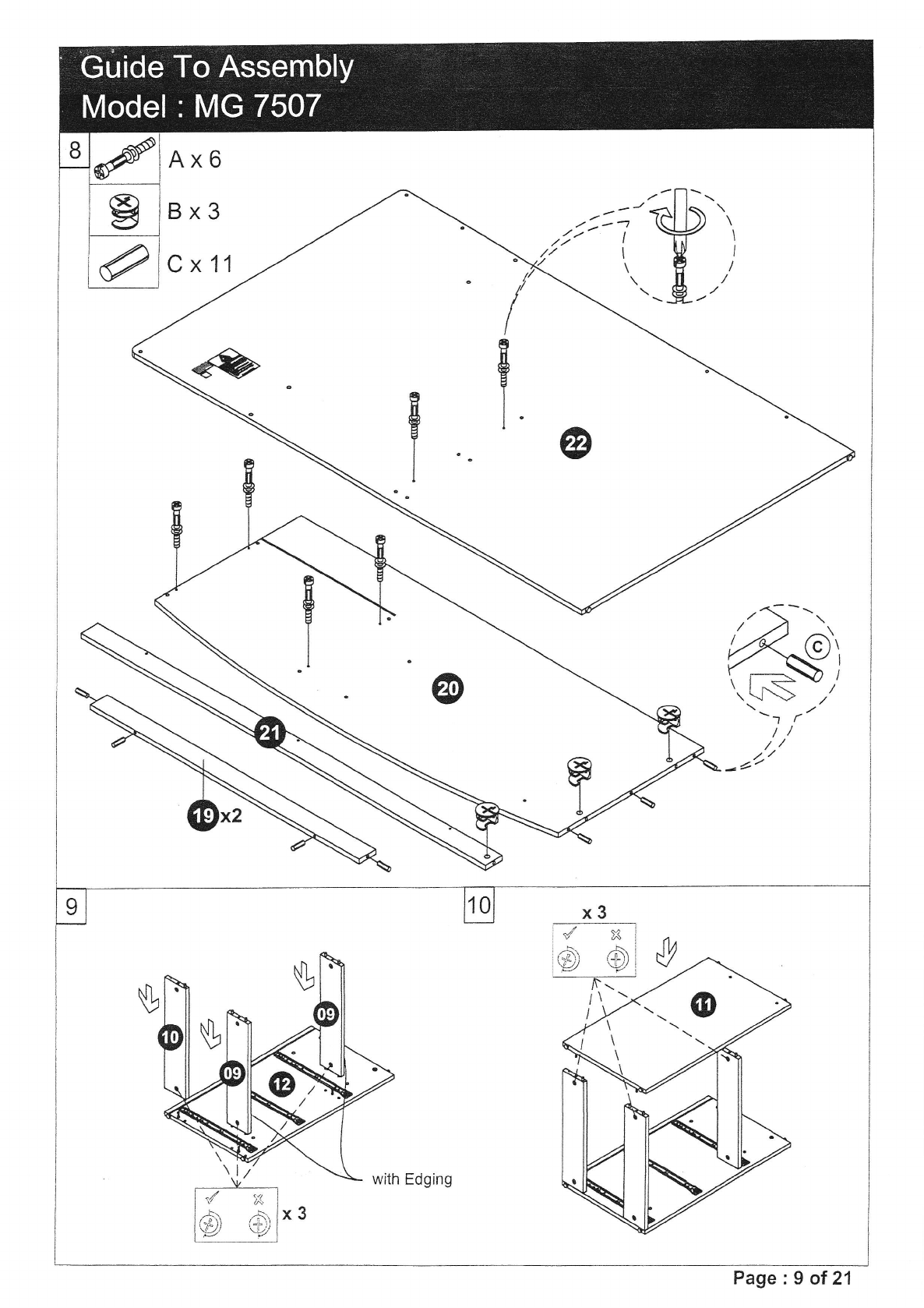
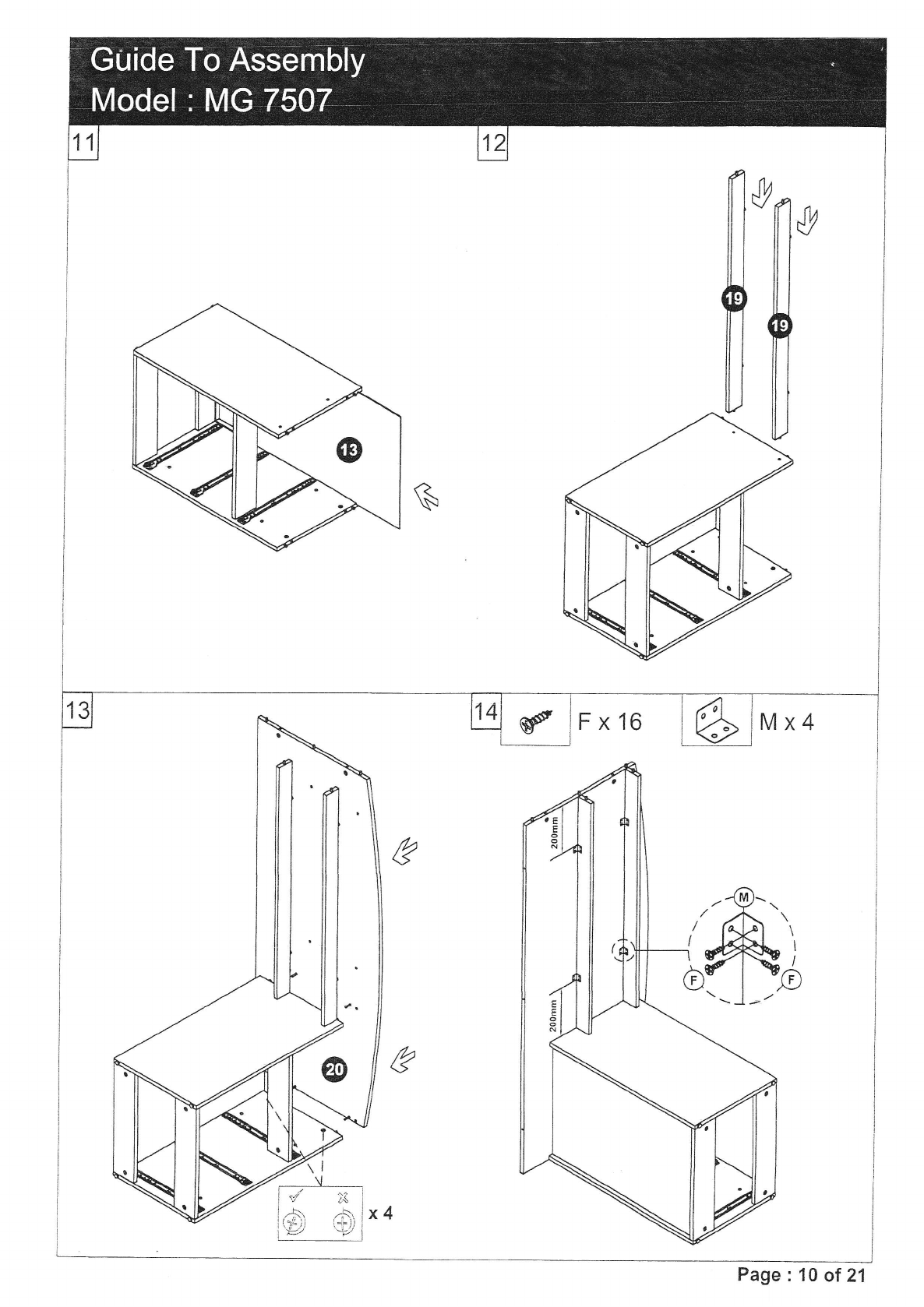
2' For ease and speed of assembly, we recommend that before you commence each step of the assembly,
Please identify all the parts required for that step.
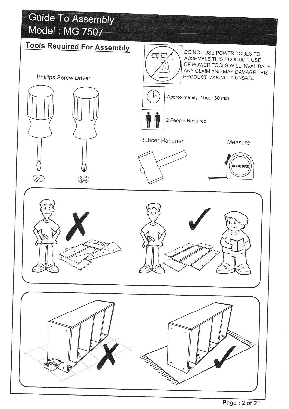
3' We recommend that where possible, alJ items are assembled nea. to the area in which they will be placed in use,
to avoid moving the product unnecessarily once assembled,
4' For the proteciion of your furniiure, particularly items of high gloss finish, we recommend that the product is placed on a
Protected surface during assembly to prevent-any damagJ.
5' During assembly please take care not to over-tighten any fittings, as this may damage the product.
.+ Please periodically check all fittings and retighten as necessary.
* To clean your item, please use a damp cloth and wipe clean.
' Never allow any kind of liquid to remain on your furniture. Absorption can cause wood to warp or finishes to de-laminate.
r Piease do not place hot items (e.g hot drinks) directly on the wood surface.
. Please do not drag or pull your furniture.
IMPORTANT INFORMATION
1. Thickness of mattress should not exceed 225mm.
2. Children should be discouraged from playing on top of this bunk bed.
3' The bunk bed should be checked periodically by the owner to ensure that the guardrail, ladder, and other components
are maintained in the correct position and state'of repair and that ali connector! are tight.
4' A bunk bed is not to be placed near a ceiling fan unless the distance between the closest points on the ceiling fan bunk
Bed is at lest 2 metres.
5, Use guardrails on both sides of upper bunk.
6. Prohibit horseplay on or under bed(s).
7. Prohibii more than one person on upper bunk,
8. Use Ladder for entering and leaving upper bunk.
9' lf the bunk bed will be placed next 10 the wall, the guardrail that runs the full length of the bed should be placed against
The wall to prevent enirapment between the bed and the wall.
10. WARNING Do not use the bunk bed/high bed if any struclural part is broken or missing.
I 1' Ventilation of the room is necessary in order to keep the humidity low and to prevent mouid in and around the bed.
12' WARNING "high beds & the upper bed of bunk beds are not suitabie for children under six years due to risk of injury from falls,,;
13' WARNING "children can become trapped between the bed & the wall, a roof pitch, .the ceiling, adjoining pieces of furniture (e.g.cupboard)
and the like' To avoid risk of se,rious injury the distance betuueen the top safety u"riir, "nJ ttrE'xiLi"i"ri j*.ture shall not exceed Tsmm
nor shall be more than 225mm,'
14. always follow the manufacturer's instruction;
15, Recommended Mattress size :90cm x 190cm (uK single) with Maximum Depth o{ 22.5cm
16. This item conforms to European Safety Standards - BS EN 747_1 : 2012 + A1 : Z01S & BS FN 747_2 | 2012 + A1 : 2015
17' WARNING "Bunk beds and high beds can present a serious risk of injury from strangulation if not used correcily. Never attach or hang
items to any part of the bunk bed that are not designed to be used wlth tfie bed, for example, but not limited to ropes, strings, cords,
hooks, belts and bags"
18' H.igh beds -and the upper bed of bunk beds is suitable for a maximum mattress thickness of 1g2mm. The top of mattress musi not come
above the line marked on the bed.
STRANGULATION HAZARD:
19' Never attach or hang items to any part of the bunk bed that are not designed for use with the bed for example, but not
limited to hook, belt and jump ropes. Page :1 of 21

DO NOT USE POWER TOOLS TO
ASSEMBLE THIS PRODUCT. USE
OF POWER TOOLS WILL INVALIDATE
,ANY CLAIM AND MAY DAMAGE TFIIS
PRODUCT MAKING IT UNSAFE.
Phillips Screw Driver
Approximately 2 hour 30 min
2 People Required
Rubber Hammer Measure
@@
Page :2 of 21

Carton L of 4Carton 3 of 4
No. Part Name Pcs No. Part Name Pcs
08 Right End Panel 101 Bottom Panel (Wardrobe) 1
22 Ladder Right Panel 1a2 Back Support Panel (Wardrobe) 1
48 Ladder Left Panel 103 Left Panel (Wardrobe) 1
04 Top Panel (Wardrobe) 1
Carton 2 of 405 Back Panel (Wardrobe) 1
23 Ladder Bottom Panel 106 Right Panel (Wardrobe) 1
24 Left Panel (lst Step) 107 Door (Wardrobe) 1
25 Risht Panel (1st Step) 113 Back Panel (Chest Drawers) 1
26 Ladder Step (1st Step) 119 Bottom Support (Desk) 2
27 Left Panel (2nd Step) i20 Top Panel (Desk) 1
28 Right Panel (Znd Step) 12L Back Panel (Desk) 1
29 Ladder Step (2nd Step) 1
30 Left Panel (3rd Step) 1Carton 4 af 4
3i Right Panel (3rd Step) 109 Support Panel (Chest Drawers) 2
32 Ladder Step (3rd Step) 110 Bottom Panel (Chest Drawers) 1
33 Left Panel (4th Step) 111 Left Panel (Chest Drawers) 1
34 Right Panel (4th Step) 112 Right Panel (Chest Drawers) 1
43 Ladder Step (4th Step) 1L4 Back Panel (Drawer) 3
44 Left Panel (5th Step) 115 Left Panel (Drawer) 3
45 Right Panel (sth Step) 116 Right Panel (Drawer) 3
46 Ladder Step (5th Step) 1L7 Bottom Panel (Drawer) 3
47 Ladder Back Panel 118 Front Panel (Drawer) 3
49 Door 136 Back Guardrail 1
s0 Door 437 Front Guardrail 1
3B
39
40
4L
42
Suppoft Rail
LVL Slat
Back Support Rail
Ladder Back Support Rail
Hanging Rail (451mm)
2
L4
1
2
1
Assembly Instructions + Fitting List
Page :3 of 21


Carton 4 of 4
Fitting List
No. Part Name Pcs
ACam Stud (smatl) d59
BCam g59
cM8 x 25mm Wood Dowel e109
D45mm Chipboard Screw d8
E38mm Chipboard Screw f12
F14mm Chipboard Screw f105
G* 14" Drawer Slide (SJ) a3 set
f{* Hinges Arm (Dix) RT 3 set
J* Hinges Arm {VSV) qs 10 set
K6/8 Complete Helder @2
LDoor Stopper a1
M6/B L Braket .41
b4
N1745 PVC Handle eI
PM8 Square Nut @4
O MB x 60mm Allen Bolt d4
RM6 x 40mm Allen Bolt {10
SMO x 30mm Allen Bolt /32
TM6 x 25mm Allen Bolt 6/ 17
UMO Allen Wrench 22
VMB Allen Wrench 21
Caution
There are many small components
used in the construction of this
unit.These loose items should be
kept away from young children
whilst assembling your unit. As
an extra precaution, screw cover
caps should be permanently
fixed in position.(Where applicable)
USEFUL HINTS & TIPS
Two people will be required to
assemble this unit
Please keep this assembly
instruction for future reference
Page :5 of 21

Ax8
BxB
C x 16
F xT
Lx1
Hx3
\\1\
A\
.l
I
-TIJ \I
t
I
I
I
WHEN FITTING CAMS
ENSURE STARTING POSITION IS CORRECT
BEFORE YOU INSERT CONNECTiNGBOLT
TURN CLOCKWISE UNTIL SECURE
l@l
+f
CORRECT
L@J bl
FA
WRONG
Page :6 of 21

I
ffi
with Edging
g
Fx6
Kx2 s*
@
\ lAt
Page:7 of21

Ax6
B x 10
Cx14
F x 18
Gx3sets
)
I
I
WHEN FITTING CAMS
ENSURE STARTING POSITION IS CORRECT
BEFORE YOU INSERT CONNECTING BOLT
TURN CLOCKWISE UNTIL SECURE
L@l
+f
CORRECT
L@l @l
AA
WRONG
To Assembly the Drawer Slide, Please Follow Step as Belor.r
oo 0 oO o O o
Page :8 ot21

Ax6
Bx3
Cx11 t7'- '1
I\I
--r r
t/
-1'
Page :9 of 21
wiih Edging

F x 16
?{
-\.
'.J-!.j
/
Page :1A of 21

Dx3
Tx3
-\\-
\-1\\
Page :11 of 21

Tx5
r'r
Page :12 of 21

Px2
Qx2
Rx2
Tx1
Fx6
Hx3
T-----'1
Nx1
,O--..
e"
?\
)s- t
.6) /
Page :13 of 21

x2
l/*,
iv (j,s !
iR
| / .-ll .\\ ,'-.q- 1 l
,\-iry; \J),) |
',v11
Do This Step 3 Times
Nx3 F x12
Do This Step 3 Times
Gx3sets
@^
\\i4l
rh-
V6
Do This Step 3 Times
re
Do This Step 3 Times
Page :14 of 21
Do This Step 3 Times

Ax4
B x32
Cx56
Fx20
J x 10 ,@;\,
? 9'.,
M,) I
I
I
I
I
I
@-tt
tu)
\---l
' br,'l
6@
.?tg@
R* Ll
d
Page :15 of21

A x 16
\
I
I
)
ll-
1t
\1
x4
//\ !
d ;dl
-... a I
,g) ,t7 I
x
A
i':.ri
=/
Page :16 of 21
with Edging

with Edging
g
Page :17 of21

x2
a^i -*;-
Al
i,---t-\ ,?\ F
Iqt, {8, i
\- - |
d
x2
aa Y"i
lf,{l
ie) s)) |
i * -,::,_)
with Edging -''
d
%
%t
x2
a7- ^-l
l.\ *r P
rft) t:ti I
l- r t
Page :18 ot21

F x2A
Jxlo&
w
/-, @
Page :19 of 21

Tx4
\ts
Rx4
Sx2
Page:24 of21
Table of contents
Other nest Indoor Furnishing manuals
Popular Indoor Furnishing manuals by other brands

CopperOptics
CopperOptics PairGain PG-Flex FCS-719 manual

J.Burrows
J.Burrows JBBRISS8BK Assembly instructions

TIMBER ART DESIGN
TIMBER ART DESIGN SR 890047 Assembly instructions

FACTO
FACTO 40035018 Operator's manual

Rauch
Rauch M9980 Assembly instructions

URBAN OUTFITTERS
URBAN OUTFITTERS RILEY PLATFORM BED Assembly instructions