VS4XX_Troubleshoot.doc Rev 0002A
Troubleshooting Tips
Video Switcher VS4X1
This table covers the NetMedia Video Switcher VS4X1
Symptom Description Recommended Action
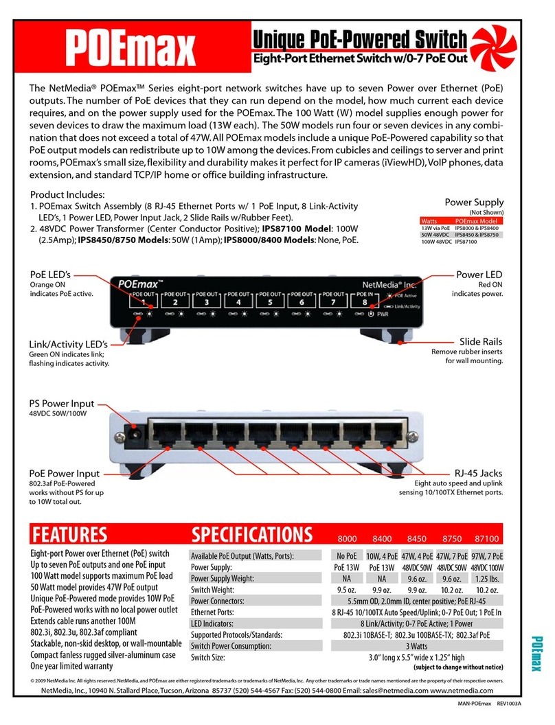
VS4X1 does not work. 1. The VS4X1 requires 12V DC 100mA
power and good signal connections.
2. The Black RCA connector is for
Output. The Yellow RCA connectors
are Inputs.
1. Disconnect and reconnect power supply. Make sure all other connections
are secure.
2. Ensure that the Black Output connector is used to send signal to the
receiving device.
VS4X1 settings do not
change after switches
are changed.
3. VS4X1 power must be disconnected
between each switch change.
3. Disconnect and reconnect power supply. Check for changes in rotation
time or umber of sources.
Do not see all inputs.
4. VS4X1 must have a good video
signal.
5. The VS4X1 starts with input 1 and
then rotates through 2, 3, and 4. If
programmed for 3 inputs, then 1, 2, and
3 are used. If programmed for2 inputs,
then 1 and 2 are used.
4. Ensure good signal from each input device. Test input device
independently through a monitor.
5. Ensure that video devices are plugged into correct inputs of VS4X1.
Also
Test by programming for 1 sec interval and 4 inputs (switches 6, 7, 8 ON).
Also
Check switch 7 and 8 programming for correct number of inputs.
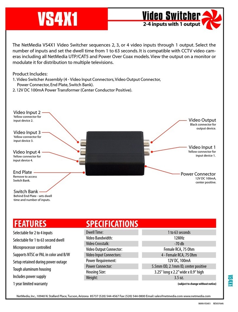
Wrong rotation order. 6. The order is 1, 2, 3, 4, 1, 2, 3, etc.
Input 1 is next to power connector.
Input 2 is opposite the power connector.
Input 4 is opposite the Black Output
connector.
6. Reconnect devices to desired input number.
Video Switcher VS4X4
This table covers the NetMedia Video Switcher VS4X4
Symptom Description Recommended Action
VS4X4 does not work. 1. The VS4X4 requires 12V DC 100mA
power and good signal connections.
2. Front LEDs are NOT in line with rear
connectors. Output 1 is nearest the
power connector. Next are Outputs 2, 3,
and 4. Inputs 1, 2, and 3 follow. Input 4
is furthest from the power connector.
3. Each Output can be disabled by
pressing the minus (-) button.
4. Each Input can be independently
disabled on each Output by pressing
the minus (-) button.
1. Disconnect and reconnect power supply. At least one Input and one
Output LED should be on or flashing. Make sure all other connections are
secure.
2. Arrange devices to the correct input and Output connections.
3. Check Output LED, if it is flashing then it is disabled. Press the Output
Selector button until its LED is lit again. Then press the plus (+) button to
enable the Output. Its LED should be on without flashing.
4. Select desired Output with Output Selector button. Press the Input
Selector button until Input LED is lit. If it is flashing, then it is disabled.
Press the plus (+) button to enable the Input. Its LED should be on without
flashing.
Rotation order is
scrambled.
5. Front LEDs are NOT in line with rear
connectors (see #2).
5. Arrange devices to the correct Input and Output connections.
Output does not
rotate.
6. Each Output can be individually
programmed for 1 to 4 inputs ( see #3).
7. Each Output rotation can be stopped
on an individual Input.
8. Rotation time can be as long as 4
minutes and 15 seconds.
6. Ensure that Output is programmed for more than one Input.
7. Restore Output to rotation mode by selecting Rotation Status LED.
8. Set shorter rotation time.
Unable to program
rotation time.
9. Rotation time is only programmable
within 10 seconds of selecting Rotation
Status LED.
10. Rotation time begins at 0 every time
new programming begins.
9. Press Input Selector button until Rotation Status LED is on again. Time
Status LED should also be on. Immediately program rotation time.
10. Reprogram Rotation time using 0 as starting point. Each press of 10
SEC button adds ten seconds, each press of 1 SEC button adds one
second.
T
R
O
U
B
L
E
S
H
O
O
T
I
N
G
S
I
T
C
H
E
R
S
NetMedia, Inc. 10940 N. Stallard Place, Tucson, Arizona 85737 (520) 544-4567 Fax: (520) 544-0800
mailto:sales@netmedia.com http://www.netmedia.com


