manuals.online logo
Brands
  1. Home
  2. •
  3. Brands
  4. •
  5. Omron
  6. •
  7. Switch
  8. •
  9. Omron D40ML Series User manual

Omron D40ML Series User manual

D40ML Series
Safety,
Technology
& Innovation
Operating Instructions for D40ML Series
IMPORTANT NOTE: Read and understand these instructions before installing, operating, or maintaining this equipment. The product is designed to
be a component of a safety oriented control system. It is the responsibility of each user to ensure the correct overall functionality of its systems and
machines. Omron STI its subsidiaries and affiliates, cannot guarantee all of the characteristics of a given system or product not supplied by Omron
STI.
WARNING: Do not defeat, tamper with, remove or bypass this unit. Severe injury to personnel could result.
D40ML Heavy Duty Switch Dimensions (mm)
D40ML Medium Duty Switch Dimensions (mm)
Operation:
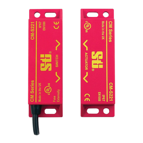
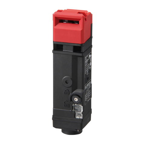
All D40ML series safety switches are designed to conform to EN60947-5-3 and be used as directed by ISO14119, EN ISO12100 and EN60204-1. They have
coded RFID sensing which provides a wide (>10mm) sensing distance and provide a high tolerance to misalignment after sensing. They can operate in extreme
environments of temperature and moisture. The switches are provided factory coded either uniquely or by series master code.
Installation:
• Installation of all D40ML series safety switches must be in accordance with a risk assessment for the individual application.
• The use of a safety relay is required for monitoring RFID coded switches. These relays monitor two redundant circuits as per ISO13849-1 for up to
PLe/Category 4 protection.
• D40ML series switches are designed to operate with most dual channel safety relays to satisfy EN60947-5-3.
• M5 mounting bolts must be used to mount the switches. Tightening torque for mounting bolts to ensure reliable fixing is 1.0 Nm. Always mount on non-ferrous
materials.
• Do not mount adjacent switches or actuators closer than 30mm.
• To achieve nominal holding force ensure face-to-face alignment of magnetic parts.
• After installation always check each switch function by opening and closing each guard individually in turn and ensuring that the Green LED on the switch and
the LEDs on the safety relay are illuminated when the switch is closed and are extinguished when the switch is open. Check that the machine stops and
cannot be re-started when each switch is open.
Maintenance/Safety Checks: Monthly: Check alignment of actuator and look for signs of mechanical damage to the switch casing or cables.
The safety functions and mechanics must be tested regularly. For applications were infrequent guard access is foreseeable, the system must have a manual
function test to detect a possible accumulation of faults at least once per month for PLe Cat3/4 or once per year for PLd Cat3 (ISO13849-1). Where possible it is
recommended that the control system of the machine demands and monitors these tests, and stops or prevents the machine from starting if the test is not done.
(ISO14119). Check that the machine stops and cannot be re-started when each switch is open.
NOTE: The safety outputs will only close when the actuator is in place and the lock magnet is energized. Forcing open of the lock will cause the safety outputs to
open.
IMPORTANT: The guard lock function is power-on applied and power-off released. It may not be used for person protection on machines with rundown. The Risk
Assessment for the particular application should include the risk of spare actuators. Spare actuators should not be readily available and must be securely
controlled. Record any RFID codes as required by factory rules or with reference to any risk assessment for the particular application and user location.
Manual P/N 99983-0020 022016 Rev.C
©2016 Omron Scientific Tetchnologies, Inc. All rights reserved.
EU Declaration of Conformity
The manufacturer named below herewith declares that the product
fulfills the provisions of the directive(s) listed below and that the
related standards have been applied.
OMRON Scientific Technologies Inc.
6550 Dumbarton Circle
Fremont, CA 94555, U.S.A.
Directives applied:
Machinery directive 2006/42/EC
EMC directive 2004/108/EC (valid until 19th April 2016)
EMC directive 2014/30/EU (valid from 19th April 2016)
RoHS Directive 2011/65/EC
Standards applied:
EN 60947-5-3:2013
EN 60947-5-1:2004+AC:2005+A1:2009
EN 60947-1:2007+A1:2011
EN ISO 13849-1:2008:+AC:2009
EN 62061:2005+AC:2010+A1:2013
EN ISO 14119:2013
Fremont, Date: August 12, 2015
Marty Krikorian
Director, Quality Control
Standards: ISO14119 EN60947-5-3 EN60204-1
ISO13849-1 UL508
:ataDytilibaileRdnanoitacifissalCytefaS
Dielectric Withstand: 250VAC
Insulation Resistance: 100 Mohms
Switching Distance: Sao 1mm Close
Sar 10mm Open
Switching Frequency: 1.0 Hz maximum
Approach Speed: 200mm/m to 1000mm/s
Body Material: D40ML-P__ = Plastic
D40ML-M__ = Die-Cast Metal
D40ML-SS__= 316 Stainless Steel
Temperature Range: -25C to +40C
Vibration: 10Hz to 55Hz, 1mm amplitude.
Shock: 11ms 30g
Enclosure Protection: IP67 (Plastic or Metal)
IP69K (Stainless Steel) with flying leads
Cable Type: PVC 8 core 6mm OD
Mounting Bolts: 2 x M5 Tightening torque 1.0 Nm
Mounting Position: Any
Power Supply: +24VDC ± 10% (selv / pelv)
Holding Force: SS2: F1max (typical): 600N Fzh: 450N
SS1: F1max (typical): 950N Fzh: 700N
P2 & M2 Version: F1max (typical): 900N Fzh: 675N
P1 & M1 Version: F1max (typical): 1500N Fzh: 1150N
Max. Switched Current (Outputs): 200mA (min. internal resistance 8.5 Ohms)
Characteristic Data according to EN ISO13849-1:
Performance Level e If both channels are used in combination
with a SIL3/PLe control device
Category Cat. 4
MTTFd 1100a
Diagnostic Coverage DC 99% (high)
Number of operating days per year: dop = 365d
Number of operating hours per day: hop = 24h
B10d: Not mechanical parts implemented
When the product use deviates from these assumptions (different load, operating
frequency, etc.) the values must be adjusted accordingly.
Information with regard to UL508
Use LVLC or Class 2 supply. Type 1 enclosure.
WARNING: Hot surface – risk of burn if used at ambient temperature of +40C degrees.
Affix a warning label to the switch.
D40ML Series
Operating Instructions for D40ML Series
Quick Connect (QC)
250mm (10”)
M12 8 -Way
Male Plug
Conductor
Colors Function
Power
Ratings
3 Blue 0VDC 50mA max. (sensing)
2 Red 24VDC
8 Orange Lock Applied (+24VDC) 500mA max. (locked)
7 Black Safety Output 1 200mA max.
1 White Safety Output 1
4 Yellow Safety Output 2 200mA max.
6 Green Safety Output 2
5 Brown Auxiliary Signal +24 VDC 200mA
Connection Colors
LED Operation and Switch Status Indication:
The D40ML switch uses 2 LED to indicate all the different possible
switch states. The LED are in a clearly visible location at either side of
the cable exit point.
Switch Status Guard Green LED Yellow LED
Locked Closed Steady Off
Solenoid Power OFF (unlocked) Closed Flashing Off
Guard Open Open Off Steady
Door Forced Open Open Off Flashing
Actuator Operating
Direction:
OMRON CANADA, INC. • HEAD OFFICE
Toronto, ON, Canada • 416.286.6465 • 866.986.6766 • www.omron247.com
OMRON ELECTRONICS DE MEXICO • HEAD OFFICE
México DF • 52.
55.59.01.43.00
• 01-800-226-6766 • [email protected]
OMRON ELECTRONICS DE MEXICO • SALES OFFICE
Apodaca, N.L. • 52.81.11.56.99.20 • 01-800-226-6766 • [email protected]
OMRON ELETRÔNICA DO BRASIL LTDA • HEAD OFFICE
São Paulo, SP, Brasil • 55.11.2101.6300 • www.omron.com.br
OMRON ARGENTINA • SALES OFFICE
Cono Sur • 54.11.4783.5300
OMRON CHILE • SALES OFFICE
Santiago • 56.9.9917.3920
OTHER OMRON LATIN AMERICA SALES
54.11.4783.5300
Authorized Distributor:
C434I-E-01 08/15Note: Specifications are subject to change. © 2017Omron. All Rights Reserved. Printed in U.S.A.
Printed on recycled paper.
OMRON AUTOMATION AMERICAS HEADQUARTERS • Chicago, IL USA • 847.843.7900 • 800.556.6766 • www.omron247.com
OMRON EUROPE B.V. •
Wegalaan 67-69, NL-2132 JD, Hoofddorp, The Netherlands.
•
+31 (0) 23 568 13 00
•
www.industrial.omron.eu
Controllers & I/O
• Machine Automation Controllers (MAC) • Motion Controllers
• Programmable Logic Controllers (PLC) • Temperature Controllers • Remote I/O
Robotics
• Industrial Robots • Mobile Robots
Operator Interfaces
• Human Machine Interface (HMI)
Motion & Drives
• Machine Automation Controllers (MAC) • Motion Controllers • Servo Systems
• Frequency Inverters
Vision, Measurement & Identification
• Vision Sensors & Systems • Measurement Sensors • Auto Identification Systems
Sensing
• Photoelectric Sensors • Fiber-Optic Sensors • Proximity Sensors
• Rotary Encoders • Ultrasonic Sensors
Safety
• Safety Light Curtains • Safety Laser Scanners • Programmable Safety Systems
• Safety Mats and Edges • Safety Door Switches • Emergency Stop Devices
• Safety Switches & Operator Controls • Safety Monitoring/Force-guided Relays
Control Components
• Power Supplies • Timers • Counters • Programmable Relays
• Digital Panel Meters • Monitoring Products
Switches & Relays
• Limit Switches • Pushbutton Switches • Electromechanical Relays
• Solid State Relays
Software
• Programming & Configuration • Runtime

Other Omron Switch manuals

Omron B3F User manual

Omron

Omron B3F User manual

Omron H5S - User manual

Omron

Omron H5S - User manual

Omron S8VS-01505 User manual

Omron

Omron S8VS-01505 User manual

Omron A3AA-90K1-00 User manual

Omron

Omron A3AA-90K1-00 User manual

Omron B3SL User manual

Omron

Omron B3SL User manual

Omron D4BL - User manual

Omron

Omron D4BL - User manual

Omron 61F-GL2KM User manual

Omron

Omron 61F-GL2KM User manual

Omron A22NN User manual

Omron

Omron A22NN User manual

Omron E2EZ-X D User manual

Omron

Omron E2EZ-X D User manual

Omron D4MC-5000 User manual

Omron

Omron D4MC-5000 User manual

Omron D4N Series User manual

Omron

Omron D4N Series User manual

Omron D5F User manual

Omron

Omron D5F User manual

Omron ER1032 User manual

Omron

Omron ER1032 User manual

Omron ER5018 User manual

Omron

Omron ER5018 User manual

Omron FZ-DU User manual

Omron

Omron FZ-DU User manual

Omron D4BL - User manual

Omron

Omron D4BL - User manual

Omron A165K - User manual

Omron

Omron A165K - User manual

Omron A22K User manual

Omron

Omron A22K User manual

Omron D4D-R Series User manual

Omron

Omron D4D-R Series User manual

Omron E3JM - User manual

Omron

Omron E3JM - User manual

Omron H2F - User manual

Omron

Omron H2F - User manual

Omron D5B - User manual

Omron

Omron D5B - User manual

Omron D2MQ Series User manual

Omron

Omron D2MQ Series User manual

Omron D4A-N - User manual

Omron

Omron D4A-N - User manual

Popular Switch manuals by other brands

Qlogic SANbox 5000 Series Interface guide

Qlogic

Qlogic SANbox 5000 Series Interface guide

HIK VISION DS-3E0318P-E/M quick start guide

HIK VISION

HIK VISION DS-3E0318P-E/M quick start guide

Planet GSW-4804SF Quick installation guide

Planet

Planet GSW-4804SF Quick installation guide

Connect Pro Master-IT SUN SR-14 user manual

Connect Pro

Connect Pro Master-IT SUN SR-14 user manual

Tripp Lite NG8POE owner's manual

Tripp Lite

Tripp Lite NG8POE owner's manual

Tripp Lite NetDirector B024-H4U16 owner's manual

Tripp Lite

Tripp Lite NetDirector B024-H4U16 owner's manual

Planet WGSW-28040 user manual

Planet

Planet WGSW-28040 user manual

Tripp Lite B020-U08-19-IP owner's manual

Tripp Lite

Tripp Lite B020-U08-19-IP owner's manual

3One data IPS7112G-4GS-8GPOE user manual

3One data

3One data IPS7112G-4GS-8GPOE user manual

Cisco Nexus 5000 Series manual

Cisco

Cisco Nexus 5000 Series manual

ELBRO SMSB482-V3 user manual

ELBRO

ELBRO SMSB482-V3 user manual

Allied Telesis AT-PC232/POE datasheet

Allied Telesis

Allied Telesis AT-PC232/POE datasheet

Niko 410-000 Series quick start guide

Niko

Niko 410-000 Series quick start guide

ATEN CS-62 specification

ATEN

ATEN CS-62 specification

j5 create JUC100 user manual

j5 create

j5 create JUC100 user manual

Enabling Devices 1164 user guide

Enabling Devices

Enabling Devices 1164 user guide

Pilz PSEN ma1.4a-51 operating manual

Pilz

Pilz PSEN ma1.4a-51 operating manual

SIMON RWA HE 083 Brief Instruction

SIMON RWA

SIMON RWA HE 083 Brief Instruction

manuals.online logo
manuals.online logoBrands
  • About & Mission
  • Contact us
  • Privacy Policy
  • Terms and Conditions

Copyright 2025 Manuals.Online. All Rights Reserved.