Netech Delta 3300 Service manual
Delta 3300 - Quick-Reference Manual-660-417
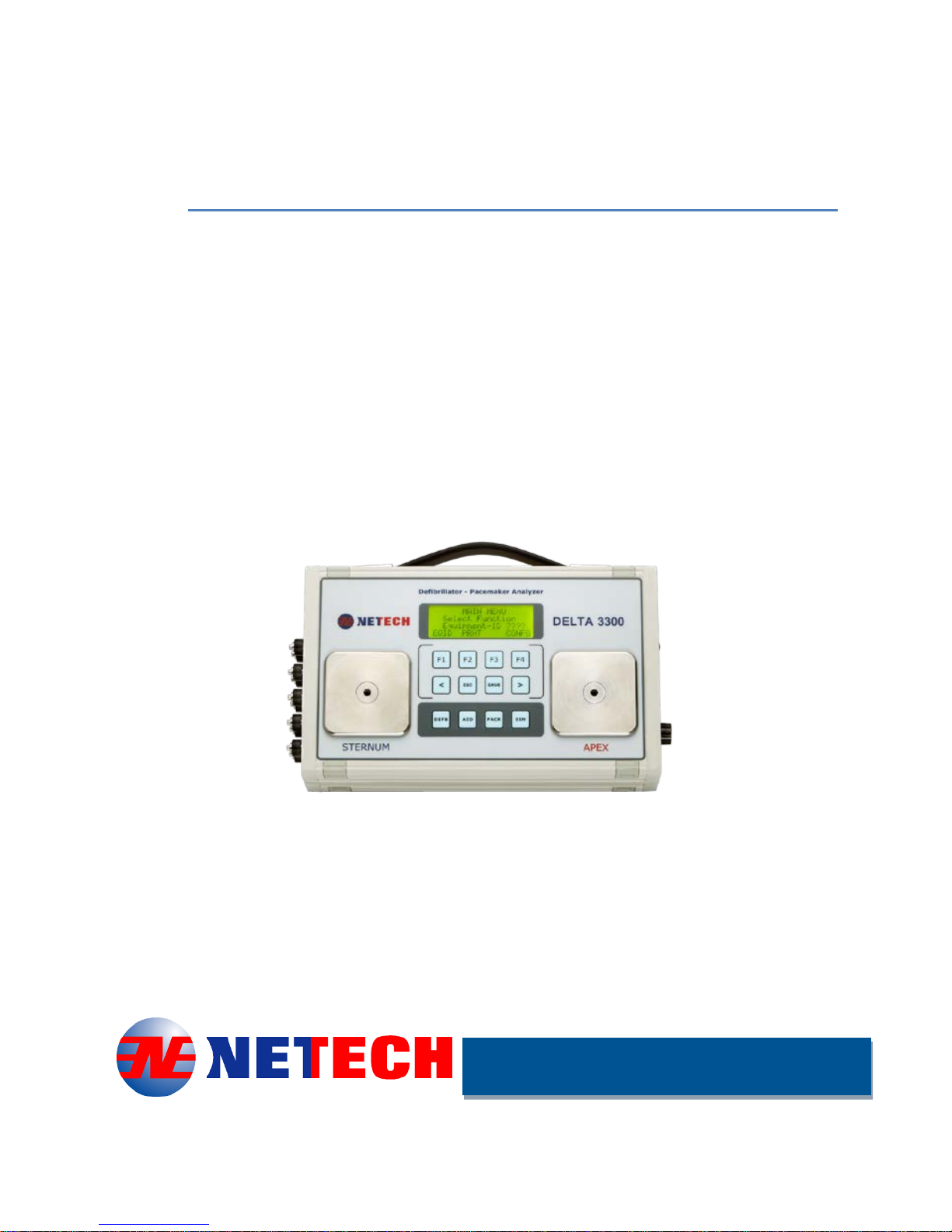
Delta 3300
Quick Reference
Manual
(Full version of the manual is included
in the CD)
►►►►Compact ►Easy to Use ►Best Value►
Defibrillator and
Transcutaneous Pacemaker
Analyzer
PN:-660-417
Innovative Instruments Since 1987

Delta 3300 - Quick-Reference Manual-660-417
Table of Contents
Notices................................................................................................1
Unpacking and Inspection of the unit ...............................................1
Contact Information..........................................................................1
Warnings..........................................................................................1
Intended User ..................................................................................2
Environment.....................................................................................2
Introduction..........................................................................................3
Delta 3300 Features ........................................................................3
Intended Use ...................................................................................4
Specifications......................................................................................4
Defibrillator Analyzer........................................................................4
Transcutaneous Pacemaker ............................................................5
General Specifications.....................................................................7
Part Numbers and Ordering Information........................................... 8
Preparation for Use .............................................................................9
Instrument Familiarization................................................................9
Serial Interface Connector:............................................................. 12
Defibrillator Testing............................................................................ 13
Introduction....................................................................................13
Equipment ID.................................................................................13
Clock Setup ...................................................................................14
Defibrillator Energy Measurement ..................................................... 15
Energy Measurement..................................................................... 15

Page | 1
Saving Test Results....................................................................... 16
Cardio version Test........................................................................ 17
Charge Time Test.......................................................................... 18
AED Shock Advisory Test.................................................................. 19
Transcutaneous Pacemaker Test...................................................... 21
Pacer Pulse Measurement............................................................. 21
Pace Refractory Test ..................................................................... 22
Sense Refractory Test ................................................................... 24
Sensitivity Test...............................................................................24
Noise Immunity Test ...................................................................... 25
ECG Simulation................................................................................. 26
Setup.............................................................................................26
Save and Print Test Results .............................................................. 28
Introduction....................................................................................28
Saving Test Results....................................................................... 28
ProComPrint Software Setup......................................................... 28
Uploading Test Results to PC........................................................ 32
ProComPrint Software Features .................................................... 32
Uploading Test Results.................................................................. 34
Warranty............................................................................................36
Delta 3300 - Quick-Reference Manual-660-417
Notices
Unpacking and Inspection of the unit
Before unpacking the DELTA 3300 inspect the shipping box for any
visual damage. If damage is found, do not unpack the unit and
immediately notify the shipping carrier. If no damage is found to the
shipping box, open the box and perform a visual inspection of the Delta
3300. If any damage to the unit is observed please contact Netech
Customer Service.
The Service Return Form may be obtained at our web site
http://www.netechcorp.us/RmaRequests or from the Netech Customer
Contact Information
Netech Corporation, 110 Toledo St. Farmingdale, NY 11735.
Phone: 631-531-0100, 1-800-547-6557
Website: WWW.NetechCorp.us
Email: sales@Netechcorp.us
Warnings
Symbol Description
Caution Important Safety
Information
Hazardous Voltage
Conforms to European Union
Directive

Page | 2
Intended User
The Delta 3300 Defibrillator Analyzer is
indented to be used only by a trained technician.
The Delta 3300 Defibrillator Analyzer intended for
testing and verifying the performance of
specifications of Defibrillators
.
The Delta 3300 should never be used in a patient
care location where it might come in contact with
a patient.
The Delta 3300 Defibrillator Analyzer is intended
to be used within the published specifications.
Any unauthorized alteration or modifications will
result in a hazardous condition or improper
operation.
Environment
The Delta 3300 should never be used in harsh
environmental conditions outside the
specifications as this will affect the performance
of the unit.
The Delta 3300 should never be used in wet
condition or in a flammable environment.

Page | 3
Introduction
The DELTA 3300 Analyzer is a precision, compact, battery operated,
instrument for testing defibrillators and transcutaneous pacemakers.
DELTA 3300 measures the energy output and ensures that the
defibrillator complies with specified requirements. It is used for
semiautomatic and automatic defibrillators with monophasic or biphasic
outputs.
The DELTA 3300 has a built-in load resistance of 50 ohms, simulating
the human body Impedance. The DELTA 3300 contact plates provide
the electrical connection between the defibrillator paddles and the load
resistance. When the defibrillator is discharged, The DELTA 3300
samples the pulse, calculates and displays the energy delivered.
In addition to the defibrillator function, DELTA 3300 tests all types of
transcutaneous pacemakers. The dedicated function keys and menu
driven display make it simple to operate. DELTA 3300 measures and
displays a pulse’s amplitude, rate, energy and width. It conducts
demand sensitivity tests, measuring and displaying refractory periods,
as well as immunity tests, which determine the pacemaker’s
susceptibility to 50/60 Hz interference.
Delta 3300 Features
Simple to use, utilizing dedicated function keys and a menu
driven interface.
Compact and light weight.
Large 20 X 4 Character display with back lighting.
Tests Monophasic and Biphasic outputs.
Charge time measurement.
Auto Range - Energy measurement.
Cardio version delay measurement.

Page | 4
Waveform storage and playback function.
12 lead ECG output.
7.4 Volt LI Ion batteries.
1M internal flash memory for storing test records.
Rs 232 interface for uploading test data.
Intended Use
The Delta 3300 is indented to be used to determine the performance
specifications of the defibrillators and transcutaneous pacemakers
Specifications
Defibrillator Analyzer
Energy Output Measurement:
Maximum Energy: 800 J
Display Resolution: Based on Auto Range
Auto Range: 2 - 9.99 J, 10-99.9 J, 100-800 J
Resolution:: 0.01 J ( 2 -9.99), 0.1 J (10-99.9), 1 J (100-500)
Accuracy: ±1 % of reading ± 0.1 J (2-9.9), ± 1J (10-99), ± 2 %
(100-500)
Load Resistance:
50 ohms ±1 %; non-inductive (< 1 μH)
Sampling Time: 20 uS
Measurement Time Window: 60 ms
Absolute Max Peak Voltage: 5000 V
Absolute Max Peak Current: 100 A
Pulse Width: 60 ms
Waveform Storage / Playback:
Discharge waveform: ECG outputs leads and through paddle
contacts.
High Level Output: 100:1 Time Base Expansion

Page | 5
Sync Time Measurements:
Timing Window: Starts at each R wave peak
Test Waveforms: User selectable ECG rates.
Delay Time Accuracy: ±1 ms.
Charge Time Measurement:
Countdown Timer: User selectable - 30, 45, and 60 seconds.
Energy Charge Time: Display the charge time measured from
the time the start button is pressed to the discharge.
Transcutaneous Pacemaker
Test Load Range:50 to 1100 ohms in step of: 100 ohms.
Accuracy: 50 - 500 ohm ±1 %, 500 - 1100 ohm ±1.5 %
Pulse Measurements:
Amplitude: 4 to 400 mA (50 ohm load)
Accuracy: ± 1 % or ± 1mA
Max. Amplitude: 400 mA all loads
Rate: 30 to 800 ppm
Accuracy: ±1 % or 2 ppm
Pulse Width: 0.5 to 50 ms
Accuracy: ±1 % or ±0.3 ms
Demand Sensitivity Test:
Waveforms: QRS, Square (SQR), Triangle (TRI), and
Haversine (SSQ)
Waveform width: 40, 50, 60, 70, 80, 90, 100, 200, 300, 400 ms
Pacer Rate: 30 to 120 ppm
ECG Output:
Amplitude: User selectable: 0.1, 0.25, 0.5, 1.0, 1.5, 2.0, 2.5, 3.0,
3.5, 4.0 and 5 mV

Page | 6
Pacer Input (Load dependent):
Amplitude (50 ohm): 0 - 10 mV
Resolution (50 ohm): 25 μV
Amplitude: (500 ohm): 0 - 100 mV
Resolution: (500 ohm): 1 mV
Accuracy: ±2%
Immunity Test:
Interference Signal: 50Hz / 60 Hz
ECG signal Amplitude:0.5 to 5.0mV
Refractory Period Measurement:
20 to 500 ms (both Pacing and Sensing)
Accuracy: ± 5 ms
Patient Simulator
Waveform Simulation: ECG (NSR),
ECG Rate: 30, 40, 50, 60, 70, 80, 90, 100, 110, 120, 130, 140,
150, 160, 170, 180, 190, 200, 220, 240, 260, 280, 300, 310
BPM
Accuracy: ± 1%
Amplitude: 0.1, 0.25, 0.5, 1.0, 1.5, 2.0, 2.5, 3.0, 3.5, 4.0, 4.5,
5.0 mV.
Accuracy: ± 2% @ Lead II (Square Wave)
Output Impedance: RL to all leads 1000 ohms.
High Level Output: 0.5 V/mV of low level (lead II)
Arrhythmia Selections:
Ventricular Fibrillation Coarse (VFBC)
Ventricular Fibrillation Fine (VFBF)
Ventricular Tachycardia (VTAC)
Atrial Fibrillation (AFIB)

Page | 7
Performance Waveforms:
Sine, Square, Triangle:
Rate: 0.2, 0.3, 0.4, 0.5, 1, 2, 3, 4, 5, 6, 7, 8, 9, 10, 15, 20, 25,
30, 35, 40, 45, 50, 55, 60 Hz.
Amplitude: 0.1, 0.25, 0.50, 1, 1.5, 2.0, 2.5, 3.0, 3.5, 4.0, 4.5, 5.0
mV.
Amplitude accuracy: ±2 % (Square Wave -Lead II 1.0 mV )
Pacer Pulse:
Pulse width: 10 mS.
Rate: 120 PPM.
Amplitudes: 1.0 mV (Lead II)
Amplitude accuracy: ±2 % (Lead II 1.0 mV)
General Specifications
Temperature Range:
Operating: +15°C to +35°C ,
Storage: 0°C to +50°C.
Display:
Type: LCD with LED back lighting.
Alphanumeric format: 4 lines by 20 characters.
Data Input/Outputs (2):
RS-232C (1) for Computer control.
Power: 7.4 Volt Li Ion Battery. 100-230 VAC input 8.5V Battery
Charger.
Housing: High impact ABS Plastic case.
Dimensions: D x W x H: 10.25 x 6.25 x 2.5 Inch.26 X 16 x 6.4
Cm
Weight: 1.5 kg / 3.3 lbs. with Battery.

Page | 8
Part Numbers and Ordering Information
Part No: 660: DELTA 3300 Defibrillator / Transcutaneous
Pacemaker Analyzer (All Standard Accessories are
included).
Standard Accessories:
661: Internal Paddle Contact Adapters
660-CD: User and Service Manual DELTA 3300
660-HHS-001: Li-ion Battery (7.4V/850mA)
660-PADDLE-ADAP: Defibrillator Paddle
Adapter (2)
660-610-6353: Standard Pacemaker Adapter
cable
660-HARD-CASE: Hard Carrying Case
660-ProComPrint: ProComPrint Software
Ver1.0 (Open Source)
Optional Accessories:
661-651-HP:Interface cable for HP (AED Model
Specific)
660-651-PHYSIO: AED interface cable for
Physio control
660-651-ZOLL: AED Interface Cable for ZOLL
660-PRO-PRINT-VR2: PRO-Print Software
(Version 2.0)
660-250-RS 232-USB: Standard Rs 232 to USB
cable
Note: Various manufactures model specific interface
cables are available.Please call for the part number or
visit www.NetechCorp.us
Page | 9
Preparation for Use
The Delta 3300 is shipped with the following items included in
the customized hard case:
•Delta 3300 Defibrillator / Transcutanious Analyzer.
•Li Ion Battery Charger (110/220 V input)
•Paddle contact adapter for AEDs (2 Pieces)
•Transcutaneous Pacer Interface cables
•User manual / Print software CD
Before getting started it is important to get
familiar with the control and operation of the
unit.
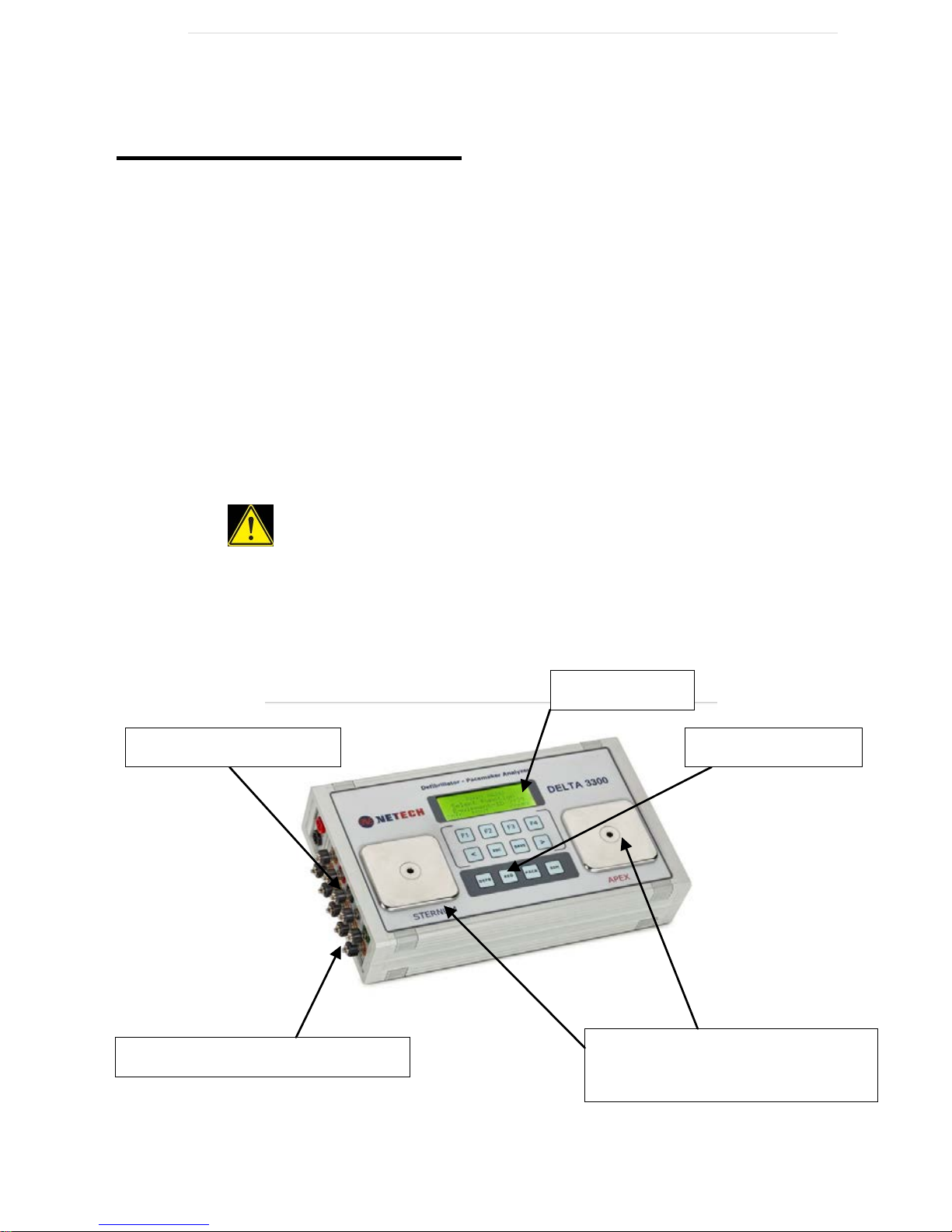
Instrument Familiarization
LCD Display
Defib. Contact Plates
50 Ohms input load
Main Function
ECG High Level
10 Lead Universal ECG

Page | 10
Display
The Delta 3300 incorporates a high contrast 20 X 4 LCD display
with LED back lighting for easy viewing.
Key Pads
The keypad utilizes soft touch tactile keys, providing a fluid
resistant barrier to the internal circuitry. When a key is pressed
a beeping sound will be heard to indicate that the key is
activated. The dedicated key functions and interactive menu
make it easier to use.
The following are the description of the key functions; F1, F2,
F3, F4, <, and >.
These keys are interactive associated with the respective
function selections.
“ESC”:Brings you back to the previous menu.
“SAVE”: Saves the displayed test data in to the storage
memory under the unique ID of the unit under test.
“DEFB”: Displays the Defibrillator Test Function. Additional
selections are available with F1, F2 and F4 in the menu.
“AED”: Displays the AED Test Function. Additional selections
are available with F1, F2 and F4 in the menu.
“PACER”: Displays the transcutaneous Pacer Test Function.
Additional selections are available with F1, F2, F3, F4, < arrow
and >arrow in the menu.
“SIM”:- Pressing the key will display the Simulator Function.
Additional selections are available with F1, F2, F3 and F4.

Page | 11
Paddle Contacts Plate.
Defibrillator paddle contacts are marked “APEX” and
“STERNUM”.
Do not use AED pads directly on the paddle
contacts. Use the insulated paddle contact cover
included with the unit and the recommended cables
for the particular AED model.
ECG Output Connectors:
10 universal patient lead connecters color-coded for easy
identification of the leads.
ECG High Level Output Connectors:
High level ECG output connectors are marked on the side panel
next to the ECG leads.
Power ON/OFF Switch:
The power ON/OFF switch is located on the right side panel.
This switch powers the unit on/off.
Pacer Input Connector:
Transcutaneous Pacer input connections are marked ‘Trans.
Input’.
Pacer Input Load Selector:
Transcutaneous input load can be easily selected by using the
rotary switch.
Battery Charger Input connector:
DC jack (2.1mm)- Li Ion battery charger Input connection.

Page | 12
Serial Interface Connector:
D-sub 9 connector located on the right side panel provided for
establishing communication with PC for uploading test data
using the supplied RS232 or the optional RS232 /USB interface
cable.
Battery Compartment:
The Battery compartment is located on the back of the unit. It
contains a 7.4 Volt Li-Ion rechargeable battery specially
designed for the unit with a built-in protection circuit. The
battery is partially charged prior to shipment.
When the unit is powered, it checks the battery condition and if
it detects a low battery condition a warning message will appear
on the display.
To continue operation, connect the charger to a live outlet.
When the battery is fully charged the red led on the charger will
turn to green.

Page | 13
Defibrillator Testing
Introduction
The Delta 3300 can be turned ON by sliding the ON/OFF switch
located on the right side panel. When the unit is first powered,
the screen momentarily shows the software version and the
build number then will display the Main Menu as shown below.
In this menu the user can input a 4 digit Equipment ID of the
unit under test (DUT). The test results that are saved will be
designated under this unique ID and available for uploading to a
PC and print. Therefore it is very important to change the ID
when a new unit is being tested.
Equipment ID
Press F1 for the equipment ID set menu. Use F1, F2, F3, F4 to
toggle the digits from 0-9. When done press the “SAVE” key.
The Equipment ID is now saved and will be displayed in the
main menu.
To change the ID go back to the previous step.
Defibrillator Test Menu

Page | 14
Clock Setup
The Analyzer has a real time clock. The clock is setup at the
factory. The test results saved under the Equipment ID set
along with date and time. Therefore it is important to reset the
time clock to the region where the unit is used. The time, date,
month and year can be set individually from the ‘CONFG’)
menu.
To reset the time follow the steps:- (Time is set in the order
Hour, Minute, Second)
•From the main Menu press F4 (‘CONFG’)
•From The ‘Configuration Menu’ press F1 (‘TIME’) to set
Hour, Minute and Seconds.
•Use F1 or F2 to set the hour.
•Press F4 (‘NEXT’) to change the minute. Use F1 or F2
to set the minute.
•Pres F4 for setting the seconds. When done press
“ESC” key to the ‘Configuration Menu’.
To reset the Month, Date and Year follow the steps:- (The
sequence is Month, Date and Year)
•From the ‘Configuration Menu’ press F4 (‘DATE’. Use
F1 or F2 to change the month displayed.
•Press F4 (‘NEXT’) to set the Date. Use F1 or F2 to
change the Year.
•Press F4 (‘NEXT’) to set the Year. Use F1 or F2 to
change the Year.
•When done press ‘ESC’ twice to the main Menu.

Page | 15
Defibrillator Energy Measurement
From the main Menu, select the Defibrillator function by
pressing “DEFB” key. The following screen will be displayed.
The three measurement functions of the defibrillator are energy,
Cardio version (sync time), charge time.
The contact plates of Delta 3300 are marked APEX (+) and the
STERNUM. Securely place the defibrillator’s APEX and
STERNUM to the respective contact plates on the Delta 3300.
This ensures correct signal polarity of the stored waveform
through the high level output ECG leads and through the
paddle contacts. Reversal of this configuration will not damage
or give incorrect energy readings. However, the polarity of the
oscilloscope output will simply be reversed.
Energy Measurement
WARNING
When testing a defibrillator, follow the
manufacturer’s test protocols and safety
precautions.
Defibrillator Test Menu

Page | 16
•Set desired energy on the defibrillator.
•Discharge the defibrillator. When the unit detects the
voltage, the flashing ‘????’ on the screen stops and
the discharge energy as well as peak voltage and
current will be displayed.
•An important feature of the Delta 3300 is the auto
ranging function, which ensures precision energy
measurements. Energy readings under 10 will be
displayed with 2 decimals, 10 joules to 100joules
one decimal, and over 100 Joules no decimal.
•The pulse waveform is captured and saved until the
next discharge. The waveform can be viewed
through the paddle contact on the defibrillator, or on
the defibrillator ECG leads, or on a scope through
the High level output jacks.
•To view the waveform through the paddle or through
the ECG leads or on a scope, press F4 “Wout”. The
waveform will be expanded 100 times the time base.
•If the defibrillator is discharged again, the current
reading will be erased and the new energy reading
along with the peak voltage and current will appear
on the display. The stored waveform will be
overwritten with the new discharge pulse.
Saving Test Results
To save the test result displayed each time after discharge,
press the save key.
All saved test results will be saved in the internal flash memory,
tagged with the Equipment ID set in the earlier step. As many
as 2000 test records can be saved in the internal memory.

Page | 17
For uploading test results to a PC refer to “Print” section in this
manual.
Cardio version Test
1. From the defibrillator menu select “Card” with F1 for the
cardio version menu as shown below. The default
waveform is set to ECG @ 80BPM.
2. Set the defibrillator in synchronous mode.
3. For synchronizing the ECG through the ECG leads,
connect the ECG leads of the defibrillator to the ECG
output connectors. The defibrillator will synchronize with
the ECG rate and instantly discharge the energy. The
energy and the sync time will be displayed.
4. To set the ECG rate and measure the sync time press
F1. Each time F1 is pressed the rate will be increased
by 10 BPM.
5. To change the amplitude of the ECG press F4 and
select the desired amplitude. The selected amplitude will
blink and the amplitude will update.
6. To save the cardio test result press save. The cardio
version (Sync) time and the ECG rate and the amplitude
set will be saved under the Equipment ID entered
earlier.
Table of contents
Popular Health Care Product manuals by other brands


Bradley
Bradley S19-921H Installation

LiteCure Medical
LiteCure Medical LightForce FX user manual

Stryker
Stryker EOLE DC 32" Operation and maintenance manual

DrBrowns
DrBrowns Deluxe Bottle Sterilizer User instructions

Refit
Refit SHC-CM1 product manual

Medical Alarm
Medical Alarm MediPendant MED01 owner's manual