NetPing IO R401 User manual

[ENG] NetPing IO R401, User Guide

[ENG] NetPing IO R401, User Guide -
2
Содержание
[ENG] [R401] 1. Introduction....................................................................................... 4
[ENG] [R401] 2. Limitation of Liability and Copyright ............................................... 5
Limitation of Liability and Copyright ................................................................................................ 5
[ENG] [R401] 3. Connectors and Indication Elements............................................... 6
[ENG] [R401] 4. Installation and Connection ............................................................. 9
[ENG] [R401] 5. Connection of sensors..................................................................... 11
Sensors of the "Dry Contact" type .................................................................................................. 11
Connection of the Liquid sensor (mod.2605) ................................................................................. 11
NetPing Supply Voltage Sensor 995S2............................................................................................ 13
PIR detector (mod.M105-1E)............................................................................................................ 14
External NetPing AC/DIN socket...................................................................................................... 15
Buzzer (mod.STD-3025) ................................................................................................................... 15
Airflow sensor + GRID 120 * 120 * 10mm NC ................................................................................... 16
[ENG] [R401] 6. Using IO Lines for Managing External Devices (in the «Output»
Mode)......................................................................................................................... 18
Electrical parameters of IO lines (IO1- IO2)..................................................................................... 18
Equivalent circuit ............................................................................................................................. 19
Electrical parameters of input lines (I3–I4)..................................................................................... 19
Equivalent circuit ............................................................................................................................. 20
[ENG][R401] 7. Resetting Settings to Default Values ............................................... 21
[ENG] [R401] 8. Additional Documents and Links ................................................... 22
[ENG] [R401] 9. Warranty Obligations ...................................................................... 23
[ENG] [R401] 10. Operation Conditions and Storage .............................................. 24

[ENG] NetPing IO R401, User Guide -
–

[ENG] NetPing IO R401, User Guide -[ENG] [R401] 1. Introduction
[ENG] [R401] 1. Introduction
–
•
•
•
[ENG] [R401] 1. Introduction
This guide will help you get acquainted with the specialities and features of the NetPing IO R401, get an idea of its
functionality and technical characteristics and prepare the device for operation.
This User Guide is designed for network administrators and users, who set up or operate the device. To work with
the device properly, a user must have an idea about the principles of building and functioning of local networks as
well as possess the next knowledge and skills:
Basic knowledge in the area of local and global networks;
Basicknowledgeintheareaofarchitectureandprinciples of work of TCP/IP networks;
Basic knowledge in the area of architecture and principles of work of Ethernet networks.

[ENG] NetPing IO R401, User Guide -[ENG] [R401] 2. Limitation of Liability and Copyright
[ENG] [R401] 2. Limitation of Liability and Copyright
–
[ENG] [R401] 2. Limitation of Liability and Copyright
Limitation of Liability and Copyright
The information, contained in this document, can be changed by the manufacturer without a prior notice. Although
every effort was made to make the information in this document accurate and without errors, the manufacturer is
not liable for their possible presence and for the consequences that may result from the errors herein. The
manufacturer is not liable if supplied equipment, software and this user guide does not correspond to expectations
of a user and his/her opinion about where and how to use all the above. All copyrights on supplied devices,
described in this User Guide, as well as firmware and software of devices and this User Guide belong to NetPing
global Ltd. Сopying, replication and translation of this user guide to other languages are not allowed without a
prior written permission of a rightholder. Copying, replication, changing, disassembling of provided softwareare
not allowed without a prior written permission of a rightholder.For the part of software that is provided in source
codes, there is a separate license agreement, which defines an order of its use and modification. Other trademarks
used in this description belong to corresponding rightholders.

[ENG] NetPing IO R401, User Guide -[ENG] [R401] 3. Connectors and Indication Elements
[ENG] [R401] 3. Connectors and Indication Elements
–
[ENG] [R401] 3. Connectors and Indication Elements
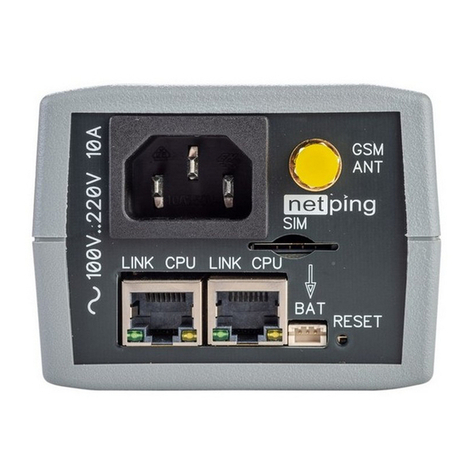
The front panel of the NetPing IO R401 device is shown in this image:
There are two Ethernet 10/100-BASE-TX connectors on the front panel of the device. The device can be connected
to the Ethernet network using any of these connectors. The second connector can be used to connect any network
devices including other NetPing devices.
Connectors and indication elements:
Element Function
DC IN 12V power connector

[ENG] NetPing IO R401, User Guide -[ENG] [R401] 3. Connectors and Indication Elements
[ENG] [R401] 3. Connectors and Indication Elements
–
Element Function
Eth ports 2x 100 BASE-TX Ethernet
CPU An indicator of the device operation. The indicator flashes when it transmit
packets to the network. Fast flashing occurs when the device is reset to
initial (factory) settings
LINK An indicator of the device operation. It flashes when it receives packets.
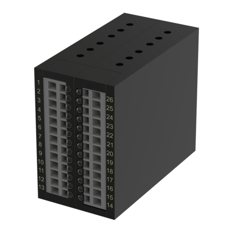
The back panel of the NetPing IO 254R301 device is shown in this image:

[ENG] NetPing IO R401, User Guide -[ENG] [R401] 3. Connectors and Indication Elements
[ENG] [R401] 3. Connectors and Indication Elements
–
Element Function
IO1...2 Input/output lines
I3...4 Input lines
12V External sensors power output 250mA
5V External sensors power output 250mA
GND Ground
Default Reset button to the factory settings. In order to reset you need to turn on the
device with the button held down, wait until the CPU indicator stops flashing and
release the button.

[ENG] NetPing IO R401, User Guide -[ENG] [R401] 4. Installation and Connection
[ENG] [R401] 4. Installation and Connection
–
[ENG] [R401] 4. Installation and Connection
In order to connect the device follow these steps:
1. Remove the device from its packaging.
2. Connect the devices which you need (see «Connection of sensors» section).
3. Connect the power supply unit to the power connector.
4. Insert the power supply unit into an electrical socket. The power indicator will light up.
5. Insert the Ethernet-cord into any Ethernet-connector of the devicer, connect it to the switch or directly to the
network card of the computer.
6. IP address was set by default. Fot the initial setting of the device make sure that the address of your computer is
located in the same IP-subnet as the address of the device. For example, the address which is set on the computer
can be 192.168.0.11 mask 255.255.255.0.

[ENG] NetPing IO R401, User Guide -[ENG] [R401] 4. Installation and Connection
[ENG] [R401] 4. Installation and Connection
–
•
•
7. For the initial configuration of the device parameters using the web-interface, make sure that the device
responds to the ping command at its IP address.
8. In order to configure the device, open the web-interface of the device using this address http://192.168.0.100 with
the help of a browser (it is recommendable to use the latest version of Google Chrome). In order to authorize, use:
Login: visor
Password: ping
Further configuration of the device is carried out in the web-interface of the device.
Attention! The description of the web-interface can be found in a separate document DKSF 561.X IU, where X —
the number of a firmware version of the device, which description you use.

[ENG] NetPing IO R401, User Guide -[ENG] [R401] 5. Connection of sensors
[ENG] [R401] 5. Connection of sensors
–
[ENG] [R401] 5. Connection of sensors
Sensors of the "Dry Contact" type
The sensors of the 1-Wire model range are connected with 1-wire plugs RJ12 with the possibility to use extension
cords and splitters. The maximum loop length of 1-wire network, connected to one connector is restricted to 50
meters. It is possible to connect up to 8 temperature sensors and 4 humidity sensors in total at the same time.
Sensors of the "dry contact" type include a door sensor etal, opening button sensors and other the pricipal of
functionality is based on the closing/opening of the conductor. The sensor is connected to the IO1 ... 2 or I3 ... 4 lines
of the device according to the table. The order in which the wires are connected does not matter.
Loop Terminal
The first wire One of the lines IO1...2 or I3...4
The second wire GND
The maximum allowed loop lenght is 100 meters.
Liquid sensor (mod.2605)
Coloured cable Terminal
Black GND
Red +5V
Green One of the lines IO1...2 or I3...4
It is strictly prohibited to connect sensors and external modules to the Netping devices with power on!
The configuration of the device and receiving notifications from the sensors are in the document "Firmwear
description».
Attention! The sensors of the "dry contact" type: a supply volyage sensor 995S2, a liquid sensor and other are
connected to IO1...2 lines of the device or to input lines. You can conect any 4 sensors from this set.
Attention! The corresponding IO-line must be switched to the "input" mode in the device settings.
Connection of the
The number of connected liquid sensors is resricted by free IO-lines and input lines of the device. When you carry
out the connection, by guided by the colour of the heat shrink tubing at the end of the wire.

[ENG] NetPing IO R401, User Guide -[ENG] [R401] 5. Connection of sensors
[ENG] [R401] 5. Connection of sensors
–
•
•
While connecting the sensor:
"1" — norm;
"0" — alarm.
The sensor is supplied with a 2 m connection cable. You can extend the length of the cable usingCable 4 extenders,
4m, which are connected in series into each other, or independently using any wire with a cross section of at least
0.4 mm2. The maximum permissible loop length is 100 meters.
The sensor has two connectors on different sides 6p6c for connecting to the monitoring device and 4p4c for
connecting to the sensitive cable.
Attention! The corresponding IO-line must be switched to the "input" mode in the device settings.

[ENG] NetPing IO R401, User Guide -[ENG] [R401] 5. Connection of sensors
[ENG] [R401] 5. Connection of sensors
–
Coloured cable Terminal
Black (common) GND
Red (Normally closed contact) One of the lines IO1...2 or I3...4
White (Normally open contact) One of the lines IO1...2 or I3...4
The sensor is supplied with a non-detachable cable with a lug at the ends. You can extend the length of the cable
using Cable 4 extenders, 4m, which are connected in series into each other, or independently using any wire with a
cross section of at least 0.4 mm2. The maximum permissible loop length is 100 meters.
PIR detector (mod.M105-1E)
PIR detector is connected with a four-wire line in accordance with the table.
The sensors of the "dry contact" type: a supply volyage sensor 995S2, a liquid sensor and other are connected
to IO1...2 lines of the device or to input lines. You can conect any 4 sensors from this set.
Attention! The corresponding IO-line must be switched to the "input" mode in the device settings.

[ENG] NetPing IO R401, User Guide -[ENG] [R401] 5. Connection of sensors
[ENG] [R401] 5. Connection of sensors
–
Cable (coloured) Cable (flat) Terminal
Green Marked (red) wire One of the lines IO1...2 or I3...4
White The first wire after the marked one GND
Black The second wire after the marked one GND
Red The third wire after the marked one +12 V
The sensor is supplied with a non-detachable cable with a lug at the ends. You can extend the length of the cable
using Cable 4 extenders, 4m, which are connected in series into each other, or independently using any wire with a
cross section of at least 0.4 mm2. The maximum permissible loop length is 100 meters.
External NetPing AC/DIN socket
The number of connectedNetPing AC/DIN sockets is restricted only by the number of free IO-lines.
When you connect the socket, you will use all the wires, except the brown (white) one. The IO-line to which the
NetPing AC/DIN socket is connected should be put into the "Input" state. When the state is "log. 0 "on the IO-line at
the socket there will be 220 V - the load will be turned on. When the state is "log. 1 ”on the IO-line, the socket will be
withour power, the load will be disconnected.
The management of external sockets from IO-lines:
Coloured cable Terminal
Red +5V
Black GND
Blue (green) One of the IO1...2 lines
Buzzer (mod.STD-3025)
Coloured cable Terminal
While One of the IO1...2 lines (in the«output» mode, log. 1)
Attention! The sensors of the "dry contact" type: a supply volyage sensor 995S2, a liquid sensor and other are
connected to IO1...2 lines of the device or to input lines. You can conect any 4 sensors from this set.
Attention! The corresponding IO-line must be switched to the "input" mode in the device settings.
Attention! The brown (white) wire is not used and should be left disconnected.

[ENG] NetPing IO R401, User Guide -[ENG] [R401] 5. Connection of sensors
[ENG] [R401] 5. Connection of sensors
–
Coloured cable Terminal
Coloured GND
A logic level on the line in the "output" mode used for power supply will control the operation of the buzzer. When
log. 1 - the beacon is active, at log. 0 - the beacon is off.
The sensor is supplied with a non-detachable cable with a lug at the ends. You can extend the length of the cable
using Cable 4 extenders, 4m, which are connected in series into each other, or independently using any wire with a
cross section of at least 0.4 mm2. The maximum permissible loop length is 100 meters.
Airflow sensor + GRID 120 * 120 * 10mm NC
This sensor is a "dry contact" type sensor, so the order of connecting wires does not matter. The number of
connected sensors is restricted only by the number of free IO1...2 and I3...4 lines.
Cables Terminal
The first wire One of the lines IO1...2 or I3...4

[ENG] NetPing IO R401, User Guide -[ENG] [R401] 5. Connection of sensors
[ENG] [R401] 5. Connection of sensors
–
Cables Terminal
The second wire GND
Depending on the input (IO1 ... 2 or I3 ... 4) which the sensor is connected to on the terminal block, it is displayed on
that channel IO1 ... 2 or I3 ... 4 in the device web interface.
The sensor is supplied with a non-detachable cable with a lug at the ends. You can extend the length of the cable
using Cable 4 extenders, 4m, which are connected in series into each other, or independently using any wire with a
cross section of at least 0.4 mm2. The maximum permissible loop length is 100 meters.
Attention! The corresponding IO-line must be switched to the "input" mode in the device settings.

[ENG] NetPing IO R401, User Guide -[ENG] [R401] 6. Using IO Lines for Managing External Devices (in the «Output» Mode)
[ENG] [R401] 6. Using IO Lines for Managing External Devices (in the «Output» Mode)
–
•
•
•
•
•
•
•
•
•
[ENG] [R401] 6. Using IO Lines for Managing External Devices (in
the «Output» Mode)
Input-Output (IO1-IO2) lines of the device can be used both for the operation in the "input" and "output" modes for
managing external devices in contrast with Input lines (I3-I4) which function only in the "input" mode.
The configuration of IO-lines for operation in "input" or "output" modes is carried out via the managing web-
interface of the device or via the URL-encoded commands. Both IO lines can be configured independently from
each other.
IO-lines can be controlled using SNMP commands, URL-encoded commands, via the web interface, or via SMS
commands (for devices with a built-in GSM modem).
The example of application:
remote reboot of servers - an imitation of pressing down the Reset button;
remote management of the buzzer, light, a fan;
management of an electric lock, electric gate at a remote object;
management of the elements of a «smart house»: watering plants, opening-closing of blinds, a water pump,
a heating boiler, electric heaters and so on;
remote management of a power plant (a diesel generator, a gas generator).
It is possible to use auxiliary relays with the supply voltage from an external 12V source. A controlled NetPing AC/
DIN socket can be used to connect to IO lines. We can also recommend ready-made relay assemblies that can be
connected to our devices, for example a power relay (see the compatibility of this relay with the NetPing device
model on the relay page of the website).
Electrical parameters of IO lines (IO1- IO2)
In the «output» mode:
the voltage of logic «1»: +12 V, the resistance: 4,7 kOhm;
the voltage of logic «0»: 0 V, the current is up to 200 mA.
The total output current IO must not exceed the maximum current of the 12V power supply output (250mA).
In the «input» mode:
the voltage of the logic «1»: > 8,2 V;
the voltage of the logic «0»: < 3,5 V.
Attention! Correct electrical coordination of the IO lines is required when connecting external executive
devices.
Attention! IO lines are not galvanically isolated from the device! When you use relays that switch 220 V circuits,
remember about electrical safety. All operations must be carried out by specialists with the appropriate
qualifications and permission to work with this voltage.

[ENG] NetPing IO R401, User Guide -[ENG] [R401] 6. Using IO Lines for Managing External Devices (in the «Output» Mode)
[ENG] [R401] 6. Using IO Lines for Managing External Devices (in the «Output» Mode)
–
•
•
Equivalent circuit
Electrical parameters of input lines (I3–I4)
the voltage of logic «1»: > 8,2 V;
the voltage of logic «0»: < 3,5 V.

[ENG] NetPing IO R401, User Guide -[ENG] [R401] 6. Using IO Lines for Managing External Devices (in the «Output» Mode)
[ENG] [R401] 6. Using IO Lines for Managing External Devices (in the «Output» Mode)
–
Equivalent circuit
Table of contents
Other NetPing Network Hardware manuals
Popular Network Hardware manuals by other brands

General DataComm
General DataComm SpectraComm SDT Installation and operation manual

MSB Technology
MSB Technology The Premier DAC user guide

Cisco
Cisco SCE 1000 and Installation and configuration guide

ZyXEL Communications
ZyXEL Communications ONU-6040BBF-22 - V1.00 user guide

Interlogix
Interlogix TruVision NVR 11 user manual

Comway
Comway 4G DTU Configuration instructions