NetSHIELD WIPLC8D4A-RS RS232 User manual

WIPLC8D4A-RS
RS232 TO WIRELESS ETHERNET
CONVERTER WITH PLC
REVISION 1.2

Netshield WIPLC8D4A-RS User Guide 5
Contents
1. Description and specications 7
About the user guide 7
Device installer overview 7
System requirements 7
2. Installing the device installer 8
3. Adding a device to the list 9
Search for all devices on the network 9
Manually add a device to the device list 9
4. Conguring IP addresses 10
Setting the IP address manually 10
5. Conguring device settings 11
Conguring ports 11
6. Managing tasks 12
Accessing a device via Telnet 12
Accessing a device via the web interface 12
Checking device diagnostics 12
Choosing the network adapter for communication 13
7. DIP switches 14
DIP switch - SW1 & SW3 14
DIP switch - SW2 14
9. Step-by-step installation 15
Interface with the unit 15
Change the IP address 15
Change channel port setting 16
Setup the WLAN 19
10. Connecting the Ports. 20
0-20mA Interface. 20
0-20mA Interface setup. 21
0-20mA Calibration 24
TTL Interface 24
Ethernet Port Connector 26
Serial (RS232) Port Connectors 26
RS485 / RS422 Port Connectors 27
Wireless Specications 27
Netshield Contact Details 28

Netshield WIPLC8D4A-RS User Guide 7
1. Description and specications
About the user guide
This guide details the conguration and management of
devices using the Device Installer, the Web Interface and the
telnet interface. It is intended for Network Administrators re-
sponsible for the conguration and maintenance of devices on
the network.
Device installer overview
The Device Installer is an all-in-one utility for setting up various
Netshield devices on a network. It auto-detects any devices
on the network and allows conguration of network and serial
port settings. As a management tool, the Device Installer allows
for device monitoring and status verication.
System requirements
WindowsXP,Windows2000,WindowsNT4.0(withservicepack6.0a
or later), or Windows 98
Internet Explorer 5.01 or later
30MB hard drive space
64MB RAM

Netshield WIPLC8D4A-RS User Guide8
2. Installing the device installer
Before installing the Device Installer, ensure system require-
ments are met. Refer to System Requirements on page 7 for
details.
Note: The installation adds Microsoft’s .NET software onto the
system.
To install the Device Installer:
Insert the Device Installer CD into the CD ROM drive.
If the CD does not launch automatically:
a. Click the Start button on the Task Bar and select Run.
b. Enter the CD drive letter, colon, backslash, Launch.exe
(e.g., D:\Launch.exe).
The Device Installer Setup Wizard opens to guide the instal-
lation process. Click Next to open the Select Installation
Folder window.
The Select Installation Folder window prompts for a desti-
nation folder for the installation. Click Browse to change the
default destination. Click Next to open the Conrm Installa-
tion window.
FromtheConrmInstallationwindow,clickNexttobegintheinstalla-
tion.TheInstallationCompletewindowdisplayswhentheinstallation
is nished.
Click Close to exit.
1.
2.
3.
4.
5.
6.

Netshield WIPLC8D4A-RS User Guide 9
3. Adding a device to the list
The Device Installer displays a list of the devices on the net-
work. When the Device Installer initially starts, the device list is
empty. Devices may be added by performing a search for the
devices on the network or by adding them manually.
Note: Optionally, if more than one network adapter exists on
the PC, select an alternative adapter. All network com-
munication uses the selected adapter.
Search for all devices on the network
The Search tool nds all devices within the local area network
and adds them to the device list.
Manually add a device to the device list
As an alternative to using the Search tool to add devices to
the device list, add individual devices manually to the list. This
includes devices for use on the local subnet.
From the Device menu, select Add Device. The Add Device
window displays.
Enter the IP address for the device. Click OK for the Device
Installer to search for the device.
Upon connection with the device, Device Installer adds it to
the device list. A pop-up message appears if the device is
not found.
1.
1.
2.

Netshield WIPLC8D4A-RS User Guide10
4. Conguring IP addresses
Setting the IP address manually
The Search tool nds all devices within the local area network
and adds them to the device list.
From the device list, click on the device to highlight it.
From the main toolbar, click Assign IP to open the As-
sign IP Address window.
From the Assignment Method page, select Assign a specic
IP address. Click Next to open the IP Settings page.
In the IP Settings page, enter the device’s IP address, subnet
mask, and default gateway in the appropriate elds. Click
Next to open the Assignment page.
Click the Assign button to add the IP address to the device.
The Assign IP Address window indicates when the assign-
ment is complete. Click Finish to exit.
1.
2.
3.
4.
5.
6.

Netshield WIPLC8D4A-RS User Guide 11
5. Conguring device settings
Each device in the Device Installer’s list has viewable or modi-
able settings. Depending on the device type, these settings
may be viewed for each individual unit, as well as for groups of
devices.
Note: When highlighting multiple devices for conguration,
not all elds are available in the Congure Device win-
dow.
Conguring ports
Note: The WIPLC8D4A-RS, NIRS232-WI2 and the NRS232-ETH1
are congurable via their web page or by Telnet.

Netshield WIPLC8D4A-RS User Guide12
6. Managing tasks
Several device management steps may be performed through
the Device Installer. These include accessing the device via
Telnet or the device’s web interface, saving and printing the de-
vice list, verifying diagnostics and choosing network adapters.
Accessing a device via Telnet
To connect to a device using Telnet:
From the Device Installer list of devices, double click on the
appropriate device.
Click on the telnet Conguration tab. A new Telnet window
displays.
Click Connect to display the Window’s Telnet screen. Follow
the instructions displayed in the Telnet window.
Accessing a device via the web interface
Use Device Installer if a device has a web page:
From the list of devices,double click on the appropriate
device.
Click on the Web Conguration tab.
Click on the Go button to op the web pages of the device or
click on the External Browser to open the web pages on a
seperate internet explorer connection.
Checking device diagnostics
To determine whether a device is online and the network is
1.
2.
3.
1.
2.
3.

Netshield WIPLC8D4A-RS User Guide 13
functional, use the DeviceInstaller Ping option. This option
ensures the device is operating and also determines the speed
of a response from the device.
From the Tools menu, click Ping. The Ping Device window
displays.
In the IP Address box, enter the IP address of the device.
Click Ping. After several moments, the Status area displays
the ping results.
To ping another device, select Clear Status to clear the Sta-
tus area before entering another IP address.
Click Close to exit.
Choosing the network adapter for communication
By default, the primary adapter used by Windows is the net-
work adapter used for communication with devices on the
network. To select a dierent adapter:
From the Tools menu, click Options. The Options window
opens, displaying the list of available adapters.
Select the adapter by clicking its checkbox. Click Apply.
Click OK to exit.
1.
2.
3.
4.
5.
1.
2.
3.

Netshield WIPLC8D4A-RS User Guide14
7. DIP switches
The DIP switches are located on the top of the Netshield
WIPLC8D4A-RS unit. Please check the corresponding labels of
the switches to the data listed below for their function.
DIP switch - SW1 & SW3
1 Enable RS485 2-wire
2 Enable RS485 4-wire
3 RS485 RX bias
4 120OhmRS485RXtermination
5 RS485 RX bias
6 RS485 TX bias
7 120OhmRS485TXtermination
8 RS485 TX bias
DIP switch - SW2
1 Enable 4-20mA Interface
2 Enable RS232 Port 1
3Enable RS485 /RS422 Port 1
4 Enable RS232 Port 2
5 Enable RS485 /RS422 Port 2
6 (not used)
Note: Only one switch may be activated at a time in the follow-
ing sets (1,2,3), (4,5)

Netshield WIPLC8D4A-RS User Guide 15
9. Step-by-step installation
Interface with the unit
Open a terminal program (Hyper Terminal or similar) and set
the port settings as follows:
Baud Rate: 9600
Data Bits: 8
Parity: None
Stop Bits: 1
Flow Control: None
Connect a normal one-to-one serial cable (DB09 – DB09)
from the PC to Port 1 on the unit.
Note: DIP switch 2 must be in the“ON”position, and DIP switch
1 & 3 must be in the “OFF” position of SW2.
Reset the power of the unit while holding the lower case “x”
key in the terminal program to enter the user interface. The
following screen will be displayed:
Press Enter to access the setup menu.
Change the IP address
Follow the steps in “Interface with the unit” to enter the
setup menu.
Type “0” and press Enter to access the server menu.
YouwillbethenbepromptedfortheIPAddress(Displayedinbrack-
ets is the previous IP Address).
1.
2.
3.
3.
1.
2.
3.
MAC address 00204A82FD39
Software version V6.0.0.1 (050412)
AES library version 1.8.2.1
Press Enter for Setup Mode

Netshield WIPLC8D4A-RS User Guide16
Then you will be prompted for the Gateway IP Address. Type
“Y” for yes or “N” for no. If you typed“Y”, then enter the new
Gateway IP Address.
Next will be “Number of bits per host part”, where the de-
fault is “0”.
To enter or change the Telnet password type “Y” and enter
the new password.
Change channel port setting
Follow the steps in “Interface with the unit” to enter the
setup menu.
Type “1” and press Enter to change the Channel 1 port set-
tings or type “2” and press Enter to enter the Channel 2 port
settings.
Firstly the unit will ask what the baud rate of port 1 must be,
showing the previous baud rate in brackets.
The Interface (I/F) Mode is a bit-coded byte entered in hexa-
decimal notation. It can be calculated in the following table.
For example a port setting of a 8-Bit word, no parity and 1
Stop bit will give a I/F Mode of“4C”.
I/FModeOption 7 6 5 4 3 2 1 0
RS232 0 0
7-Bit 1 0
8-Bit 1 1
No Parity 0 0
Even Parity 1 1
Odd Parity 0 1
1 Stop Bit 0 1
2 Stop Bits 1 1
4.
5.
6.
1.
2.
3.
4.

Netshield WIPLC8D4A-RS User Guide 17
Use the following table to select ow control options:
Flow Control Hex
No ow control 0
XON/XOFF Flow Control 1
HardwarehandshakewithRTS/CTSlines 2
XON/XOFF pass characters to host 5
The normal port number for Channel 1 is 10001 and Chan-
nel 2 is 10002.
Enter Connect Mode options in hexadecimal notation:
Common Mode Option 7 6 5 4 3 2 1 0
Incoming connection
Never accept incoming 0 0 0
Accept with mode_control_in active 0 1 0
Always accept 1 1 0
Responce
Nothing (quiet) 0
Characterresponce(connect,disconnect) 1
Active startup
No active startup 0 0 0 0
With any character 0 0 0 1
With modem_control_in active 0 0 1 0
With a specic start character 0 0 1 1
Manual connection 0 1 0 0
Autostart 0 1 0 1
Hostlist 0 0 1 0
Datagram type
Directed UDP 1 1 0 0
Modem mode
5.
6.
7.

Netshield WIPLC8D4A-RS User Guide18
Common Mode Option 7 6 5 4 3 2 1 0
No echo 0 0 1 1
Echo & modem response (Numeric) 0 1 1 1 1
Echo & modem response (Verbose) 0 1 1 1 0
Modem response only (Numeric) 0 0 1 1 1 1
Modem response only (Verbose) 0 0 1 1 1 0
Next you have to set auto increment of the source port
where the default setting is “N”.
The Remote IP address is the destination IP address used
with an outgoing connection. Type in the Remote unit’s IP
address.
Set the Remote TCP port number for the unit to make out-
going connections. This parameter denes the port number
on the target host to which a connection is attempted.
Disconnect Mode (DisConnMode) determines the condi-
tions under which the unit will cause a network connection
to terminate. The current value is displayed in parentheses.
The following table displays the available input options:
Disconnect Mode Option 7 6 5 4 3 2 1 0
Disconnectwithmodem_control_indrop 1
Ignore modem_control_in 0
Telnetmodeandterminaltypesetup 1
Channel (port) password 1
Hard disconnect 0
Disable hard disconnect 1
State LED o with connection 1
Disconnect with EOT 1
The FlushMode (buer ushing) parameter controls line
handling and network buers with connection startup and
disconnect. Default is “00”.
The default disconnect time is 00:00.
8.
9.
10.
11.
12.
13.

Netshield WIPLC8D4A-RS User Guide 19
Enter up to two characters in hexadecimal representation.
Setup the WLAN
Follow the steps in “Interface with the unit” to enter the
setup menu.
Type “4” and press Enter for the WLAN menu.
Type “Y” to enable the WLAN or “N” to disable the WLAN.
When the WLAN is disabled the normal UTP interface
become available and can be connected to the copper
network, e.g. LAN Switch.
The next line will ask if the unit must work in an Adhoc
network (PC to Unit or Unit to Unit) or an Infrastructure net-
work. Normally these units will work in a AdHoc network.
Next will be the SSID name of the network chosen in
number 4 above.
The channel is normally “11”, but can be changed - although
it must be same as the recipient.
Set the security by choosing “0”, “1” or “2”. The unit features
WEP and WPA to secure all wireless communication. WPA is
not available when Adhoc is selected as the topology.
The wireless data rate can be set by choosing setting “0” to
“6”.
Lastly the power management can be switched on by enter-
ing “Y” or o by entering“N”.
14.
1.
2.
3.
4.
5.
6.
7.
8.
9.
Netshield WIPLC8D4A-RS User Guide20
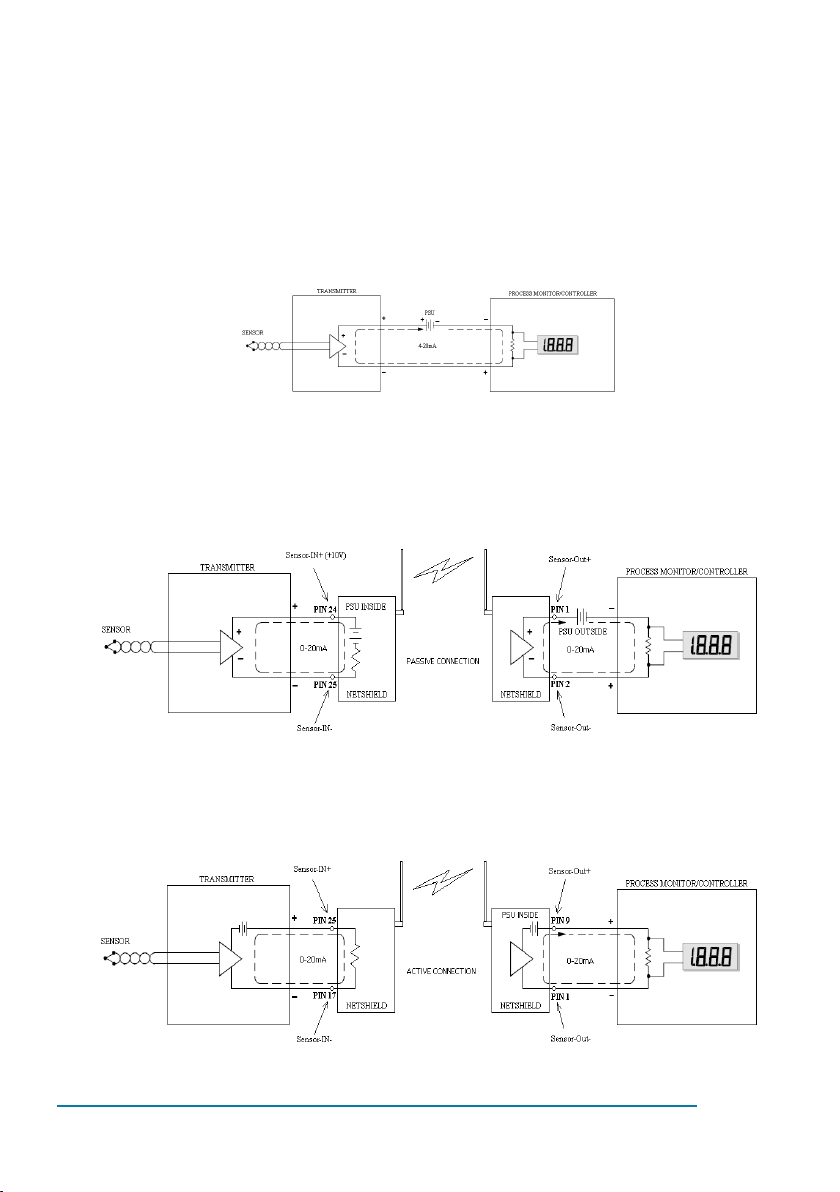
10. Connecting the Ports.
0-20mA Interface.
A typical circuit diagram is shown below.
When the sensor need a power source to convert its sensing el-
ement to current, the coupling is referred to as a“passive” type
connection. A typical passive connection diagram is shown
below.
When the sensor source its own power in the convertion proc-
ess, the coupling is referred to as an“active”connection. A typi-
cal active connection diagram is shown below.

Netshield WIPLC8D4A-RS User Guide 21
The DB25 connector pin connections can be seen on the table
below.
PIN DESCRIPTION
1SENSOR1-OUT(+) (Passive) / SENSOR1-OUT(-) (Active)
2SENSOR1-OUT(-) (Passive)
3
4
5
6
7
8
9+10V / SENSOR1-OUT (+) (Active)
10 +10V
11 +10V
12 +10V
13
14 Gnd
15 Gnd
16 Gnd
17 Gnd / SENSOR1-IN(-) (Active)
18
19
20
21
22
23
24 SENSOR1-IN(+) (Passive)
25 SENSOR1-IN(-) (Pasive) / Sensor1-IN(+) (Active)
0-20mA Interface setup.

Netshield WIPLC8D4A-RS User Guide22
To make a wireless 0-20mA connection you will need two
Netshield WIPLC8D4A-RS units. The two units must have an IP
Address, no gateway, the same SSID name and channel if used
in a wireless conguration, as in “1.4” number 5. When an Ether-
net copper interface is available the WLAN can be disabled and
the unit’s 0-20mA interface will work over the network. The end
user will need two Netshield WIPLC8D4A-RS units. These units
(UNIT-X and UNIT-Y) need to be congured as follows.
UNIT-X (Local):
Follow the steps in “1.1” (To interface with the unit) to enter
the setup menu.
Follow the step in “1.2.” (To change the IP Address) if the
unit has not got an IP Address. Remember to disable the
gateway.
In the main menu choose number “1” to enter channel 1
port settings.
Set the baud rate to“57600” bps.
I/F Mode as “4C”.
The ow control options must be “00”.
Port number is “10001”.
The Connect Mode option is “05”
Auto Increment set as“N”.
The remote IP address set as “ --- UNIT-Y --- “.
Set the remote TCP port number to “10001”
Disconnect Mode must be “00”
The FlushMode can be left to the default“00”.
The default disconnect time is 00:00.
Leave the two characters in the default condition.
Enter the “9” key to save the parameters in the main menu.
Leave for a couple of seconds and power down the unit.
Disable the dipswitches 2 and 3 and enable dipswitch 1 on
1.
2.
3.
4.
5.
6.
7.
8.
9.
10.
11.
12.
13.
14.
15.
16.
17.

Netshield WIPLC8D4A-RS User Guide 23
switch 2.
Connect the unit’s 0-20mA interface connector and the TTL
connector. Power up the unit, after a couple of seconds the
LED “RxD1” will ash.
UNIT-Y (Remote):
Follow the steps in “1.1” (To interface with the unit) to enter
the setup menu.
Follow the step in “1.2.” (To change the IP Address) if the unit
has not got an IP Address.
In the main menu choose number “1” to enter channel 1
port settings.
Set the baud rate to“57600” bps.
I/F Mode as “4C”.
The ow control options must be “00”.
Port number is “10001”.
The Connect Mode option is “C0”
Auto Increment set as“N”.
Open the IP address to“ 000.000.000.000 “.
Set the remote TCP port number to “00000”
Disconnect Mode must be “00”
The FlushMode can be left to the default“00”.
The default disconnect time is 00:00.
Leave the two characters in the default condition.
Enter the “9” key to save the parameters in the main menu.
Leave for a couple of seconds and power down the unit.
Disable the dipswitches 2 and 3 and enable dipswitch 1 on
switch 2.
Connect the unit’s 0-20mA interface connector and the TTL
connector. Power up the unit, after a couple of seconds the
LED “RxD1” will ash.
18.
1.
2.
3.
4.
5.
6.
7.
8.
9.
10.
11.
12.
13.
14.
15.
16.
17.
18.

Netshield WIPLC8D4A-RS User Guide24
0-20mA Calibration
It will be better to install the local unit, “UNIT-X”, on the current
loop transmitting side and the remote unit,“UNIT-Y”, on the
receiving side. Only the remote side will be congurable.
Set up the units and let them run for a short while.
Check if the output of the receiving unit, on the remote
side, correspond to the desired output.
If there is an error with the output, calibration is needed.
Connect a PC and the same network as the remote unit.
Open hyper terminal and give the connection some name.
In the “Connect to” window select the TCP/IP (Winsock) in
the “Connect using” eld.
In the “host adress” box, enter the remote IP adress and in
the “port number” box, enter “10001”.
When the two netshield units are operational, hyper termi-
nal will not make a connection and will give an “unable to
connect” error.
Switch o the transmitting unit (UNIT-X) and wait for one
(1) minute.
Click on the call button. There should not be any er-
rors after one (1) minute. When two minutes has lapst and
no new connection is made, the unit will default to zero
mA.
When a connection has been established, enter‘Ctrl’+
‘Shift’ + ‘6’ and a menu will appear with the commands for
the calibration.
When done with the calibration enter the‘s’ket to save and
exit.
Disconnect the call from on hyper terminal.
Connect the local unit (UNIT-X).
TTL Interface
The four (4) inputs and the four (4) outputs are connected on
the same DB25 connector. The inputs are optically isolated and
the input voltage can vary from 3.3Vdc to 16Vdc. The outputs
1.
2.
3.
4.
5.
6.
7.
8.
9.
10.
11.
12.
13.
14.
Table of contents
Popular Media Converter manuals by other brands


Hagstrom
Hagstrom KE18 user manual

SMC Networks
SMC Networks JXC 1 Series Supplementary Operation Manual

CORNING
CORNING OptiTect Gen III Series quick start guide

ZyCast
ZyCast HDME-804 User guide and installation manual

Cross Technologies
Cross Technologies 2005-02P4 instruction manual

Baumer
Baumer HOG 28 Installation and operating instructions


