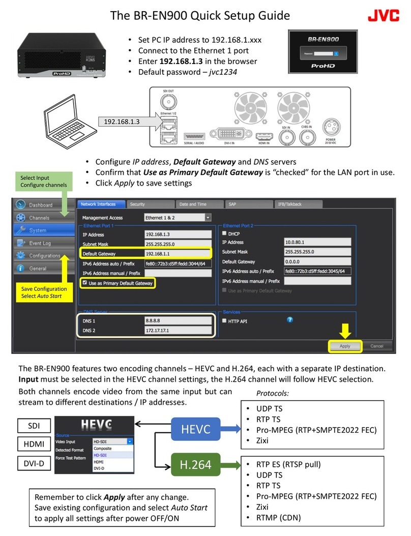
JVC MPEG-2 User manual

DM-NE300E
LST0165-001B
DM-NE300E MPEG-2 NETWORK ENCODER
MPEG-2 NETWORK ENCODER
B
Instruction Manual
POWER
STREAM
DM-NE300E MPEG-2 NETWORK ENCODER
HOLD
HOLD
USER
2Mbps
2Mbps
3Mbps
3Mbps
4Mbps
4Mbps
5Mbps
5Mbps
6Mbps
6Mbps
10Mbps
10Mbps
15Mbps
15Mbps
HOLD
USER
2Mbps
3Mbps
4Mbps
5Mbps
6Mbps
10Mbps
15Mbps
This instruction book is made from 100% recycled paper.

SAFETY PRECAUTIONS
䡵Place of storage and use
Please avoid storing or using this unit in the following
places:
●Extremely hot or cold places beyond the allowable tem-
perature for operation (0˚C-40˚C).
●Humid or dry places beyond the allowable humidity
range for operation (30%-80% RH).
●Dusty or sandy places.
●Places exposed to oil, smoke or steam, such as the
kitchen vicinity.
●Intensely vibrating or unstable places.
●Places prone to condensation.
●Places that generate strong magnetic fields, e.g., trans-
former or motor.
●Places near devices that generate electric waves, e.g.,
transceiver or mobile phone.
●Places that generate radiation, X-rays or corrosive
gases.
䡵Handling the unit
●Please do not place heavy objects on the unit, like a
monitor on TV.
●Please keep the mobile rack into the compartment. As
injury may result from fingers getting clamped.
●Please do not block the ventilation openings.
●Avoid violent shocks to the unit. Do not drop the unit.
䡵Maintaining the unit (Please turn off
the power before performing mainte-
nance work.)
Please wipe the unit with a soft cloth. Do not wipe it
with thinner or benzene lest the surface melts or be-
comes dull. For stubborn stains, wipe first with a water-
diluted neutral detergent and then wipe dry.
䡵Please use the supplied power cord.
Using a different type or damaged
cord may cause tire or electric shock.
䡵To save energy, be sure to turn off the
system when not in use.
1

SAFETY PRECAUTIONS (FOR EUROPE)
CAUTION
To prevent electric shock, do not open the cabinet.
No user serviceable parts inside. Refer servicing
to qualified service personnel.
IMPORTANT (In the United Kingdom)
Mains Supply (230 V AC)
WARNING - THIS APPARATUS MUST
BE EARTHED
The wires in this mains lead are coloured in ac-
cordance with the following code;
GREEN-and-YELLOW : EARTH
BLUE : NEUTRAL
BROWN : LIVE
As the colours of the wires in the mains lead of this
apparatus may not correspond with the coloured
markings identifying the terminals in your plug, pro-
ceed as follows.
The wire which is coloured GREEN-AND-YELLOW
must be connected to the terminal in the plug which
is marked with the letter E or by the safety earth sym-
bol or coloured GREEN or GREEN-AND-YELLOW.
The wire which is coloured BLUE must be connected
to the terminal which is marked with the letter N or
which is coloured BLACK. The wire which is coloured
BROWN must be connected to the terminal which is
marked with the letter L or coloured RED.
POWER SYSTEM
Connection to the mains supply
This unit operates on voltage of 220 V to 240 V AC,
50 Hz/60 Hz.
WARNING:
TO REDUCE THE RISK OF FIRE OR
ELECTRIC SHOCK, DO NOT EX-
POSETHIS APPLIANCETO RAIN OR
MOISTURE.
WARNING
THE UNIT CONTAINS A BUILT IN LITHIUM BATTERY FOR
MEMORY BACKUP THAT MUST ONLY BE REPLACED BY
SUITABLY QUALIFIED SERVICE PERSONNEL.
FOR BATTERY REPLACEMENT, TAKE THE UNIT TO YOUR
DEALER OR A JVC SERVICE STATION.
2

Sicherheitshinweise
䡵Betrieb und Lagerung
Lagern und betreiben Sie das Gerät nicht in
Umgebungen, in denen
●extrem hohe oder niedrige Temperaturen (unter 5°C
oder über 35°C) herrschen,
●extrem hohe oder niedrige Luftfeuchtigkeit (unter 30%
oder über 80%) herrscht,
●große Mengen Schmutz oder Staub vorhanden sind,
●das Gerät Öl, Dampf oder Rauch ausgesetzt ist (z. B.
in der Umgebung einer Küche),
●Erschütterungen auftreten können und eine
ausreichende Stabilität nicht gewährleistet ist,
●sich Kondenswasser bilden kann,
●starke Magnetfelder auftreten können (verursacht z. B.
durch einen Transformator oder einen Motor),
●elektromagnetische Wellen auftreten können
(verursacht z. B. durch einen Transceiver oder ein
Mobiltelefon),
●Strahlung (z. B. Röntgenstrahlen) oder Schadgase
austreten können.
䡵Umgang mit dem Gerät
●Stellen Sie auf dem Gerät keine schweren
Gegenstände (wie Monitore oder TV-Geräte) ab.
●Gehen Sie bei Festinstallation des Geräts mit Umsicht
vor, um Verletzungen zu vermeiden.
●Decken Sie niemals die Lüftungsöffnungen ab.
●Setzen Sie das Gerät keinerlei Erschütterungen und
Schlägen aus und lassen Sie es nicht fallen.
●Trennen Sie den Netzadapter vom Netz, wenn Sie das
Gerät nicht benutzen. Sie sparen auf diese Weise
Energie.
䡵Reinigung (Schalten Sie das Gerät
unbedingt ab, bevor Sie die Reinigung
durchführen!)
Wischen Sie das Gerät mit einem weichen Tuch ab.
Verwenden Sie keine aggressiven Reinigungsmittel wie
Verdünner oder Reinigungsbenzin, da diese die
Geräteoberfläche angreifen oder beschädigen können.
Hartnäckige Verschmutzungen entfernen Sie mit einem
weichen Tuch, welches Sie zuvor mit einer Lösung aus
Wasser und einem Neutralreiniger angefeuchtet haben.
Wischen Sie das Gerät danach mit einem weichen Tuch
trocken.
䡵Bitte verwenden Sie ausschließlich
das beiliegende Netzkabel. Die
Verwendung eines Kabels anderen
Typs oder eines schadhaften Kabels
kann die Geräteleistung beein-
trächtigen. Es besteht die Gefahr
eines Stromschlags.
䡵Schalten Sie das Gerät ab, wenn Sie
es nicht benutzen. Sie sparen auf
diese Weise Energie.
3

WICHTIG (bei Betrieb in Großbritannien)
ACHTUNG
Öffnen Sie niemals das Gehäuse des Geräts. Es
besteht Stromschlaggefahr! Im Innern befinden sich
keine vom Benutzer zu wartenden Teile. Wenden
Sie sich bei Wartungsfragen an einen qualifizierten
Servicetechniker.
NETZSPANNUNG: 230 V AC
ACHTUNG: DIESES GERÄT IST ZU
ERDEN!
Die Leiter des Netzkabels sind wie folgt farblich
gekennzeichnet:
●GRÜN-GELB : ERDE
●BLAU : NEUTRAL
●BRAUN : SPANNUNGSFÜHRENDER
LEITER
Da die Farbkodierungen des Netzkabels, welches
diesem Gerät beiliegt, nicht mit den Farbcodes der
Kontakte des Steckverbinders übereinstimmen
müssen, gehen Sie wie folgt vor:
Der GRÜN-GELB markierte Leiter muss an den
Kontakt des Steckverbinders angeschlossen
werden, der entweder mit dem Buchstaben E oder
dem Schutzerdesymbol markiert oder GRÜN bzw.
GRÜN-GELB farbkodiert ist. Der BLAU markierte
Leiter muss an den Kontakt des Steckverbinders
angeschlossen werden, der entweder mit dem
Buchstaben N markiert oder SCHWARZ farbkodiert
ist. Der BRAUN markierte Leiter muss an den
Kontakt des Steckverbinders angeschlossen
werden, der entweder mit dem Buchstaben L
markiert oder ROT farbkodiert ist.
VERSORGUNG
Anschluss an das Stromnetz
Das Gerät wird mit einer Netzspannung von 220 V
bis 240 V AC, 50 Hz/60 Hz betrieben.
WARNUNG:
SETZEN SIE DIESES GERÄT NIEMALS
REGEN ODER FEUCHTIGKEIT AUS.
ES BESTEHT DIE GEFAHR VON
FEUER ODER STROMSCHLAG!
WARNUNG
DAMIT DER SPEICHERINHALT NACH DEM AUSSCHALTEN
ERHALTEN BLEIBT, ENTHÄLT DIESES GERÄT EINE
LITHIUMBATTERIE. DIESE BATTERIE DARF NUR DURCH
EINENAUSREICHEND QUALIFIZIERTEN SERVICETECHNIKER
AUSGETAUSCHT WERDEN.
WENDEN SIE SICH ZUM AUSTAUSCH DER BATTERIE AN
IHREN FACHHÄNDLER ODER EINEN JVC-STÜTZPUNKT.
4

Netzspannung 220 V bis 240 V AC, 50 Hz/60 Hz
Stromaufnahme 0,5 A
Betriebsbedingungen 0°C bis 40°C (Kondenswasserbildung vermeiden)
Abmessungen 86 ×214 ×301 mm (ohne Bedienfeld und überstehende Teile)
Gewicht 2,8 k˝
䡵Technische Daten und äußeres Erscheinungsbild können ohne vorherige Ankündigung geändert
werden.
Filterklemme befestigen
Montieren Sie die beiliegende Filterklemme wie nachfolgend abgebildet an dem zum DM-NE300E weisenden Ende
des DV-Kabels.
zur Fixierung
anziehen
Filterklemme
überstehende
Enden kürzen
ACHTUNG
5

Diese Anlage steht in Übereinstimmung mit den Bestimmungen und Schutzanforderungen der anwendbaren EU-
Richtlinien. Diese Anlage wurde für professionelle Videoanwendungen entwickelt und ist für den Einsatz in den folgenden
Umgebungen vorgesehen:
5
Wohnbereiche (im geschlossenen Raum)
5
Handel und Leichtindustrie (z. B. Bürogebäude oder Theater)
5
innerstädtische Freiluftbereiche
Für optimale Leistung und aus Gründen der elektromagnetischen Kompatibilität empfehlen wir die Verwendung von Kabeln,
die folgende Längen nicht überschreiten:
Anschluss Kabel Länge
VIDEO OUT 1 KOAXIALKABEL (GESCHIRMT) 10 Meter
VIDEO OUT 2 S-KABEL (GESCHIRMT) 10 Meter
AUDIO OUT LEFT CINCHKABEL (RCA, GESCHIRMT) 10 Meter
AUDIO OUT RIGHT CINCHKABEL (RCA, GESCHIRMT) 10 Meter
DV 9V DV-KABEL (GESCHIRMT) 4 Meter
LAN CAT5 STP-KABEL 100 Meter
COM D-SUB-KABEL (9-POLIG, GESCHIRMT) 10 Meter
AC IN (AC-NETZTEIL) NETZKABEL 2,5 Meter
Der Einschaltstrom dieses Geräts beträgt 12,0 Ampere.
Achtung:
5Wenn in der Umgebung des Geräts starke elektromagnetische Wellen oder Magnetfelder vorhanden sind (z. B. in der
Nähe von Radios, Funkeinrichtungen, TV-Sendern, Transformatoren, Motoren usw.), kann das Bild gestört sein.
Verschieben Sie das Gerät in einem solchen Fall aus dem Einflussbereich der Störquelle.
Sonstinge Vorsichtsmaßnahmen
6

2
Thank you for choosing
JVC’s MPEG-2 network encoder
DM-NE300E.
Key Features
●PC is not required for basic operations.
●Video and audio that have been input are compressed in the MPEG-2 and MPEG-1 Layer II formats respectively
and sent to the network (100BASE-TX).
●Optimal bitrate and video quality can be selected according to the network bandwidth.
Preset bitrates can be selected on the front panel.
●DV input is possible from IEEE1394. Conversion from DV to MPEG-2 in digital is possible.
●RS232C/RS422 serial control pass-through terminal is equipped for control of external device such as video switcher.
●Standard network protocols compliant.
Stream transmission and control are RTP and RTSP compliant. Multicast/Unicast is available. Sends/Receives
serial control data via UDP.
●2U half rack size. Mounting onto EIA rack is possible.
(Use of a mount bracket (to be purchased separately) is required.)
●This encoder and decoder have some delay of audio/video due to the nature of the MPEG format.
This equipment comes equipped with a Normal mode that gives priority to video quality, as well as a Low Delay
mode to shorten delay time.
Contents
1. Points To Note When Using This Equipment.................................................................................. 3
2. Check of Accessories / Bundled Items ........................................................................................... 3
3. Names and Functions ..................................................................................................................... 4
4. How To Operate.............................................................................................................................. 6
5. Front Panel Settings ....................................................................................................................... 6
6. Attaching Clamp Filter..................................................................................................................... 6
7. Specifications .................................................................................................................................. 7
8. Caution for Cables .......................................................................................................................... 8
9. Factory Settings .............................................................................................................................. 9
10. Saving Energy ............................................................................................................................... 10
11. Others ........................................................................................................................................... 10
12. More Details on Settings ............................................................................................................... 11
12.1 Setting via Browser on the Computer ................................................................................... 11
12.2 Setting via Terminal Software on the Computer ................................................................... 23
12.3 Setting via Telnet on the Computer ...................................................................................... 28

3
2. Check of Accessories / Bundled Items
Accessories/bundled items included with the network encoder are listed as follows. Check if there is any shortage and
contact the sales outlet at which the purchase is made if necessary.
1Instruction Manual (This booklet) ................... x 1
2Warranty Card ................................................ x 1
3Power Cord (2.5m)......................................... x 1
1.
Points To Note When Using This Equipment
●This encoder and decoder have some delay of audio/video due to the nature of the MPEG format.
●Freeze or noise of playback video/audio may occur due to network conditions. These are not caused by malfunction
of the equipment.
●Be sure to enter standardized video signals into this equipment. This equipment may not function properly when
connected to some devices.
For VTRs, there may be cases where output signals may deviate from the standard during pause, stop, fast-forward
or rewind. Playback video may temporarily freeze or turn black when such signals have been input.
●Switching between [RS232C/RS422] (P.5 - ⁄.) shall be performed with the power of this equipment turned off.
Restoration using the Reset switch may be required if this is done when the equipment is on.
●Setting of the [VIDEO SELECT] switch (P.5 - *.) shall be performed with the power of this equipment turned off.
Noise interference may occur in video/audio if this is done when the equipment is on.
●Noise interference may occur in play back video or audio when altering bitrate. Pay attention to switching during
use.
●Do not turn off the power when altering settings via browsers, Telnet or terminal software. Writing into nonvolatile
memory is performed during alteration of settings. Data may lose its consistency if power is turned off during the
process and failure may occur during startup.
●NetBIOS of Windows-based Computer
When NetBIOS of Windows-based computers are enabled, broadcast packets may be sent regularly, which may
occupy the network and lead to failure in stream transmission from this equipment as well as stream reception at the
decoder. Disable NetBIOS when connecting Windows-based computers to the same LAN. To alter NetBIOS set-
tings, right click on the ‘Network Computer’ icon on the Windows screen and select ‘Properties’.
(When NetBIOS is disabled, neighboring computers will not be shown even when the ‘Network Computer’ icon is
clicked.)
●Hub Selection
Use a switching hub instead of a shared hub. All packets may be sent to devices that are not specified as the
destination if a shared hub is used. This may constrain the equipment’s operation as the equipment and the decoder
will need to perform additional processing to discard the unwanted packets.
●Other Limitations to Enable Coexistence with Multicast
When in the multicast mode, multicast packets will reach all devices within the LAN even in a system that employs
a switching hub. As a result, other network encoders will, during multicast transmission, send out voluminous amount
of packets to this equipment, thus constraining the equipment’s operation as it will need to perform additional
processing to discard the unwanted packets.
When performing multiple multicast in LAN, ensure that the total bitrate is set to 10 Mbps or less. For example, in the
case of 2 multicasts, each shall be 5.0 Mbps or less. In the case of 3 multicasts, set the bitrate for each to 3.3 Mbps
and below.
IGMPv2 compliant network is strongly recommended to build a multicast system.
●DV Input Terminal
The DV input on this equipment can only be used as AV input. It does not function as an output terminal.
4Switch Plate .................................................x 2
5Clamp Filter ..................................................x 1
4
1[10 Mbps] Switch
To set output bitrate to 10 Mbps.
Lights up when selected.
2[6 Mbps] Switch
To set output bitrate to 6 Mbps.
Lights up when selected.
3[4 Mbps] Switch
To set output bitrate to 4 Mbps.
Lights up when selected.
4[3 Mbps] Switch
To set output bitrate to 3 Mbps.
Lights up when selected.
5[6 Mbps Low Delay] Switch
To set bitrate to 6 Mbps Low Delay (low delay mode).
Lights up when selected.
6[4 Mbps Low Delay] Switch
To set bitrate to 4 Mbps Low Delay (low delay mode).
Lights up when selected.
7[3 Mbps Low Delay] Switch
To set bitrate to 3 Mbps Low Delay (low delay mode).
Lights up when selected.
8[USER] Switch
To set to output bitrate of USER’s preset value.
Factory setting is at 1.5 Mbps Low Delay.
Lights up when selected.
9[HOLD] Switch
To lock/unlock the above switches.
Switches are locked when light is on. Press this button
to unlock before operating the switches.
Light turns off when unlocked.
The above switches will be automatically locked if
left unoperated for 10 seconds.
0[STREAM] LED
Lights up when stream is transmitted from this equip-
ment to network.
![POWER] LED
Green light turns on when power in [ON].
@Power Switch
Power switch. Depress till a ‘click’ sound is heard.
䡵Front Panel
POWER
STREAM
HOLD
USER
3Mbps
Low Delay
4Mbps
Low Delay
6Mbps
Low Delay
3Mbps
4Mbps
6Mbps
10Mbps
DM-NE300E MPEG-2 NETWORK ENCODER
1
2
3
4
5
6
7
8
9
0
!
@
3. Names and Functions

5
䡵Rear Panel $[AUDIO IN] Input Terminals
Analog audio input terminals.
Disabled when DV IN terminal is used.
%[VIDEO IN] Terminal
Video (Composite) input terminal. Set the *[VIDEO
SELECT] Switch at the center when using this as
the input terminal.
^[Y/C IN] Terminal
Video (Y/C) input terminal. Set the *[VIDEO SE-
LECT] Switch at the lower end when using this as
the input terminal.
&[DV IN] Terminal
DV input terminal. Set the *[VIDEO SELECT]
Switch at the upper end when using this as the input
terminal.
*[VIDEO SELECT] Switch
To select either DV, Composite or Y/C as video in-
put. Set to [DV IN], [VIDEO IN] or [Y/C IN] accord-
ingly depending on the signal to be used.
Turn ‘OFF’ the power of this equipment when oper-
ating this switch.
([MAINTENANCE] Switch
This terminal is used only for servicing purposes.
)[SERIAL]
Serial terminal for controlling external device.
⁄[RS232C/RS422] Selector Switch
This switch sets the signal format of )[SERIAL] to
either RS232C or RS422.
Turn ‘OFF’ the power of this equipment when oper-
ating this switch.
¤[LINK] LED
Lights up when this equipment is connected to a
network.
‹[100BASE-TX] Terminal
100BASE-TX terminal. Output terminal for MPEG-2
stream.
›[RXD] LED
Lights up when this equipment receives packet via
100BASE-TX.
fiAC IN
AC 220 V~240 V inlet. Ensure to use the power cord
supplied for connection.
Make sure to earth the equipment. Do so before in-
serting the plug to the power source. When remov-
ing the earth, do so after unplugging from the power
source.
flFastener
Plug in the supplied power cable, and fasten using
the fastener.
‡Vent Outlet
(
⁄
)
*
¤
‹
›
‡
fl
fi
^
%
$
#
&
AC IN
AUDIO IN
Y/C IN
VIDEO IN
100BASE-TX
MAINTENANCE
SERIAL
RESET
RS422
RS232C
L
R
VIDEO SELECT DV IN
●Set up this equipment near a power point.
●Unplug the equipment from the power point or re-
move power cord from the AC inlet (AC IN) of this
equipment to cut off power completely.
Fasten by attaching the switch plates supplied after
setting items *and ⁄.
This shall be performed by the sales outlet at which
this equipment is purchased.
#[RESET] Switch
Use a pointed object to depress button.
This equipment will be reset.

6
Other than the front panel settings, DM-NE300E can be set via:
1. Browser on the computer (P.11)
2. Terminal software on the computer (P.23)
3. Telnet on the computer (P.28)
Details on the above methods of setting are described in P.11and subsequent pages.
Setting Using Switches on the Front Panel
Bitrate can be selected on the front panel. Bitrates and delay modes are preset for each button.
1Unlock by depressing the HOLD switch. (Light on HOLD button will turn off.)
2Select the appropriate setting switch.
3Lock by depressing the HOLD switch. (Locks automatically after about 10 seconds when left untouched.)
5. Front Panel Settings
This equipment stores changed settings and hence the same operation prior to turning off can be performed by just
turning on the power.
Setting need not be performed every time when turning on the power.
1Turn [ON] the power switch on the front panel.
The [POWER] LED and [USER] button will light up in green.
2Wait for about 20 seconds for it to be activated.
Upon activation, the [HOLD] button and other buttons that have been used prior to turning off will light up in green.
The [USER] button will light up in green when bitrates are set using a PC.
3Equipment activated.
Control of front panel settings and setting via PC as well as control from the decoder are enabled.
4. How To Operate
Attaching the supplied clamp filter to one end of DV cable which is near DM-NE300E as shown in the figure below.
6. Attaching Clamp Filter
Pull to fasten it
Clamp Filter
Cut off the
surplus portion

7
Compression format Video ISO/IEC13818-2 (MPEG-2 VIDEO)
Compression: MPEG-2
Video format: 480 i
Frame size: 720 X 576 (normal: 4.51~13.5 Mbps,low delay: 7.21~13.5 Mbps)
544 X 576 (normal: 2.70~4.33 Mbps,low delay: 4.06~6.76 Mbps)
352 X 576 (normal: 1.08~2.40 Mbps,low delay: 1.08~3.76 Mbps)
Frame rate: 25 Hz
Bitrate: CBR (38 options are available)
Audio ISO/IEC11172-3 (MPEG-1 Layer II Audio)
Compression: MPEG-1 layer II
Bitrate: Stereo 192 kbps
Sampling rate: 48 kHz
Video input Composite Video BNC/75 ¸x 1
Y/C signal S terminal x 1
Audio input Analog audio 2 Vrms RCA pin x 2(LR)
DV input DV input DV terminal x 1
Network interface 100 BASE-TX RJ-45 x 1
External control RS232C/RS422 D-sub9Pin (male) x 1
Maintenance RS-232C D-sub9Pin (female) x 1
Stream control RTSP/TCP/IP, manually
Stream output 100 BASE-TX RTP/UDP/IP, unicast/multicast
Output rate: 1.08 Mbps~13.5 Mbps
Output format: MPEG-2 Transport Stream
(ISO/IEC13818-1)
TS packet size: 188 byte
Power supply AC 220 V~240 V 50 Hz/60 Hz
Current consumption 0.5 A
Operating environment 0 °C~40 °C (Non- dew condensation )
External dimensions 86 mm x 214 mm x 301 mm (excluding terminal and protuberance)
Weight 2.8 kg
7. Specifications
䡵Design and specifications are subject to change for improvement without prior notice.

8
8. Caution for Cables
This equipment is in conformity with the provisions and protection requirements of the corresponding European Direc-
tives. This equipment is designed for professional video appliances and can be used in the following environments:
5
Residential area (in houses)
5
Commercial and light industry; e.g. offices or theaters
5
Urban outdoors
In order to keep the best performance and furthermore for electromagnetic compatibility we recommend to use cables not
exceeding the following lengths:
Port Cable Length
VIDEO IN SHIELDED COAXIAL CABLE 10 meters
Y/C IN SHIELDED S CABLE 10 meters
AUDIO IN L SHIELDED RCA PIN CABLE 10 meters
AUDIO IN R SHIELDED RCA PIN CABLE 10 meters
DV IN SHIELDED DV CABLE 4 meters
100BASE-TX CATEGORY 5, TWIST PAIR, SHIELDED CABLE 100 meters
SERIAL SHIELDED 9PIN D-SUB CABLE 10 meters
AC IN AC POWER CABLE 2.5 meters
The inrush current of this apparatus is 3.4 amperes.
Caution:
5Where there are strong electromagnetic waves or magnetism, for example near a radio or TV transmitter, transformer,
motor, etc., the picture may be disturbed. In such a case, please keep the apparatus away from the sources of the
disturbance.

9
Switch Settings
9. Factory Settings
Item Factory Setting Supplementary Note
Front Panel Setting 3 Mbps Normal Mode: 3 Mbps
Power Switch OFF
SERIAL RS232C
VIDEO SELECT VIDEO IN Composite Input selected
USER Button Settings
Item Factory Setting Supplementary Note
TS Rate 1.5 Mbps
Low Delay Low Low Delay Mode
Audio ON Audio Stream available
Software Settings
Item Factory Setting Supplementary Note
IP Address 10.0.0.1
Subnet Mask 255.0.0.0
Default Gateway Address NIL
Bitrate 3 Mbps
Low Delay Normal Normal Mode selected
Audio ON Audio Stream available
Auto Start Normal Manual Start selected
Unicast/Multicast Mode Unicast Unicast Mode selected
Multicast Stop Mode
Stopped when all decoders stop
‘When all decoders stop’ selected
Multicast IP Address 225.0.1.1
Multicast Port Number 3000
Serial Port Baudrate 9600 bps
Data Length 8
Parity None
Stop Bit 1
Flow Control None
Destination IP Address 10.0.0.100
Destination Port Number 1052

10
10. Saving Energy
Turn off the power when not in use to save energy.
11. Others
Be sure to get the sales outlet at which this equipment is purchased to mount the equipment.
All brand names and product names in this instruction manual are trademarks or registered trademarks of their
respective companies.
1. All rights are reserved with regard to a portion or the entire manual.
2. Contents of this booklet may be altered without any prior notice.
3. Our company shall not be responsible for any eventualities arising from the operation of this
equipment.
4. Photos and diagrams are enlarged, omitted or composited to ease explanation, and may slightly differ
from the actual item.

11
12. More Details on Settings
Please consult the sales outlet at which this equipment is purchased on the operating environment of com-
puters required for setting.
Note: Be sure to perform thorough checks when altering preset values, particularly network-related settings. Browser and
Telnet connections may fail and system may not operate normally if there are errors in the settings.
12.1 Setting via Browser on the Computer
Note: Please refer to computer’s instruction manual for setting of the computer.
Screen may not be properly displayed depending on the version of OS or browser used, but this will not affect the
operation of the equipment.
12.1.1 Connection with Computers
(1) Connection
Connect DM-NE300E to the computer via network. Execute the ping command to check if network connection
between the computer and DM-NE300E is successful. For example, if the IP address of DM-NE300E is 10.0.0.1,
then enter
ping 10.0.0.1
upon starting up the command prompt at the computer. A few lines of response from DM-NE300E as shown below
will be displayed if the connection is successfully established:
Reply from 10.0.0.1: bytes=32 time<10ms TTL=64
Timeout will be displayed if the connection is not established.
Request timed out.
Note: Factory settings of IP address and subnet mask of DM-NE300E are 10.0.0.1 and 255.0.0.0 respectively.
(2) Starting Up Browser Software
Start up the Internet Explorer (Version 5.5 or later) on the computer, followed by entering DM-NE300E’s IP ad-
dress (URL) in the URL input field. For example, if the IP address of DM-NE300E is 10.0.0.1, then key in the URL
http://10.0.0.1 and press Enter. The top page will be displayed on the browser. (If the top page is not displayed,
check if the URL entered is correct.)
ON shall be selected for the item ‘Automatically check for Internet Explorer Update’ under Details of Internet
Options in the Tools menu of the Internet Explorer.
Note: The x.x of vx.x shown on the screen indicates the software’s version.
vx.x
12.1.2 Top Page (Enter Password)
Enter password and click OK.
Note: Initial setting for the password is the 8-letter “password”.
Change of password is recommended for security reasons. To change the password, refer to the page on pass-
word alteration.
The Basic page will be displayed if the password is correctly entered.
If the password is incorrect, a warning message will be displayed. Return to the previous page of the browser to re-
enter the correct password.
Note: Timeout is set for access via browsers for security reasons. Access from any page of the browser will be disabled by
timeout after 1 hour has lapsed since the last setting. In this case, re-enter password at the top page.
The following top page will be displayed when the equipment is currently accessed by someone or when previous
access has not ended by Logout Button:
vx.x

12
12. More Details on Settings
12.1.3 Basic (Basic Settings)
Current parameters are displayed on this page and these can be altered at the same time. To make alterations,
select or enter a value, followed by clicking the Enter button on the bottom left. Links to other pages are located on
the uppermost portion of the page.
When entry is correct
When entry is incorrect
The Basic screen will be displayed again.
vx.x
vx.x

13
TS (Bitrate)
For selecting bitrate of MPEG-2’s TS (Transport Stream). A total of 38 options are available within the range of
1.08 ~ 13.5 Mbps. Reception via DM-ND300E decoder is possible for bitrates at 10 Mbps or below.
Although DM-NE300E is able to transmit data of higher rates, DM-ND300E is unable to decode them. Higher rates
than 10 Mbps can be used, for instance, to capture streams in files on the computer.
Delay Mode
Normal or Low Delay can be selected. Normal mode is an encoding method that gives priority to video quality,
while Low Delay mode gives priority to shorten delay time.
Audio Mode
ON or OFF can be selected. Audio bitrate is 192 kbps when the Audio mode is ON. When Audio mode is OFF, the
bitrate is assigned to video to enhance the video quality.
Start Mode
Normal or Auto can be selected. When Auto is chosen, data transmission will automatically start upon turning on
the power of DM-NE300E. When Normal is selected, data transmission starts upon access by the decoder or by
using the button on the encoder control page.
Unicast / Multicast
Data transmission/reception is carried out with one encoder and one decoder in unicast. Multicast, on the other
hand, allows data to be transmitted to multiple decoders at one time. To perform multicast transmission, select the
Multicast mode.
Multicast Stop Mode
All Decoders, Master Decoder or Manual can be chosen. When All Decoders is selected, multicast transmission
stops when all decoders participating in the multicast stop receiving data. When Master Decoder is selected,
multicast stops when the first decoder to start receiving data (Master Decoder) stops its reception. When Manual
is selected, multicast transmission does not stop even when all decoders participating in the multicast stop receiv-
ing data. In this case, use the button on the stream control page or type in command to stop data transmission.
Multicast Address
Enter 4 integral values for the IP address to be used for multicast. Select values between 224.0.0.0 and
239.255.255.255. Over 225.0.1.1 is recommended. When using multiple encoders for multicast, specify separate
multicast address for each encoder.
Multicast Port
Select a port number between 0 and 65535. Numbers below 1023 may be used by various protocols. Values
above 1024 are recommended.
Serial Port Baudrate
Select any of the following:
110 / 134 / 150 / 200 / 300 / 600 / 1200 / 2400 / 3600 / 4800 / 7200 / 9600 / 19200 / 31250 / 38400
Data Length (of Serial Port)
Select 7 or 8.
Parity (of Serial Port)
Select none, odd or even.
Stop Bit (of Serial Port)
Select 1 or 2.
Flow Control (of Serial Port)
Select None, Xon/Xoff or Hardware.

14
12. More Details on Settings
12.1.4 Encoder Control (Manual Operation of Stream Transmission)
Stream transmission can be controlled at this page. When transmitting/receiving data with the DM-ND300E de-
coder, DM-ND300E controls DM-NE300E using the RTSP protocol. In this page, data can be transmitted manually
without using the decoder. This is used for capturing stream in files by sending it to the PC.
Firstly, select either Unicast or Multicast. When Unicast is selected, only one destination is allowed. When Multicast
is chosen, data can be transmitted to multiple destinations.
•Destination IP Address (Unicast Destination IP Address)
Specify destination IP address for transmission by unicast using 4 decimal integers.
•Destination Port Number (Unicast Destination Port Number)
Specify the destination port number between 0 and 65535. Numbers below 1023 may be used by various
protocols. Values above 1024 are recommended.
•Multicast Address (Multicast Destination IP Address)
Specify multicast IP address for transmission by multicast using 4 decimal integers.
•Multicast Port Number (Multicast Destination Port Number)
Specify the destination port number between 0 and 65535. Numbers below 1023 may be used by various
protocols. Values above 1024 are recommended.
•Stream Control (Stream Transmission Control)
Press the Start button to start transmission. Stop button is displayed during transmission. Press the Stop button
to stop transmission.
Note: Change settings only in the Stop mode.
This manual suits for next models
1
Table of contents
Other JVC Media Converter manuals

JVC
JVC VN-E4U - 4 Channel Network Encoder User manual

JVC
JVC 4ch Network Encoder VN-E4 User guide

JVC
JVC JX-SV77 User manual

JVC
JVC DM-JV600U User manual

JVC
JVC KM-F700U User manual

JVC
JVC VN-A1U - Network Encoder User manual

JVC
JVC DM-JV600U User manual

JVC
JVC RX-8010VBK User manual

JVC
JVC MX-WMD90 User manual

JVC
JVC PK-VS4QXSG User manual
Popular Media Converter manuals by other brands

EMS
EMS PIEZON MASTER 700 Operation instructions

Phoenix Contact
Phoenix Contact QUINT4-PS/12DC/24DC/5/PT manual

Televes
Televes TOX Series Quick installation guide

HDTV Supply
HDTV Supply HDTVSXHDCP01 operating instructions

Allied Telesis
Allied Telesis IMC2000 Series installation guide

Erone
Erone SEL39R433-PP4 Instruction Notice