manuals.online logo
Brands
  1. Home
  2. •
  3. Brands
  4. •
  5. NetterVibration
  6. •
  7. Industrial Equipment
  8. •
  9. NetterVibration NTP Series User manual

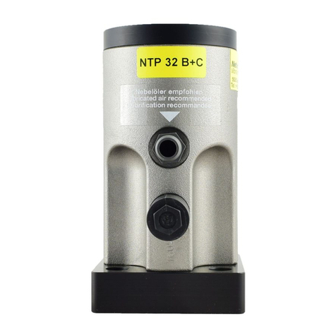
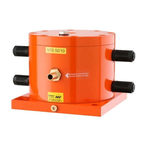
NetterVibration NTP Series User manual

Operating instructions for
Netter pneumatic linear vibrators
series NTP
Sept. 2021
No. 2016E
page 1/9
version 1
These operating instructions apply to:
NTP 18
NTP 25
NTP 32
NTP 48
Use and storage
Before installing the NTP read these instructions carefully. It is the basis for any action when dealing with
the NTP, and may be used for training purposes. The instructions should be subsequently stored at the
operation site.
Copyright
This documentation is protected by copyright.
Netter
Vibration reserves all rights such as translations,
reprinting and reproduction of the instructions, as well as parts thereof.
2
1 General information
The pneumatic linear vibrators series NTP are hereafter referred to as
"NTP".
Please refer to the delivery note for the scope of delivery.
Check the packaging for possible transport damage. In the event of dam-
age to the packaging, check the contents for completeness and possible
damage. Inform the carrier in the case of damage.
The target group for these instructions is technical staff, who have basic
knowledge in pneumatics and mechanics.
Only complying technical staff may work on the NTP.
The NTP may only be installed, put into operation, maintained, troubleshot
and disassembled by persons authorised by the operator.
All technical information, data and instructions for installation, operation
and maintenance in these instructions are based on the latest information
available at the time of printing and take our past experience to the best of
our knowledge into account.
No claims can be derived from the information, illustrations and descrip-
tions in these operating instructions.
The manufacturer does not assume liability for damages resulting from:
failure to observe the instructions,
improper use,
unauthorised repairs,
technical modifications,
use of non-permissible spare parts.
Translations are made to the best of our knowledge.
Netter
Vibration does not assume liability for translation errors, even if the
translation was made by us or on our behalf. Only the original German text
remains binding.
Before installing the NTP read these instructions carefully. It is the basis
for any action when dealing with the NTP, and may be used for training
purposes. The instructions should be subsequently stored at the operation
site.
This documentation is protected by copyright.
Netter
Vibration reserves all rights such as translations, reprinting and re-
production of the instructions, as well as parts thereof.
The pneumatic linear vibrators series NTP comply with the EC Machinery
Directive 2006/42/EC.
In particular, the standard EN ISO 12100 has been observed.
Designation
Scope of
delivery
Target group
Limitation of
liability
Use and
storage
Copyright
Directives /
standards
observed
3
2 Safety The NTP are intended for generating linear vibrations.
General applications are: loosening, conveying, sorting, compacting, sepa-
rating bulk materials and reducing friction. NTP are used for emptying
bunkers, as drives for conveyor troughs, sieves and vibrating tables.
The NTP are designed for installation in machines and may only be put
into operation, if it has been assured that the complete machine complies
with the regulations of the machinery directive.
The NTP may also be used outdoors and in dusty and humid environ-
ments. The NTP may not be submerged in bulk materials or in liquids.
The NTP B+C may only be operated clocked.
Any other use is considered improper.
Installation, commissioning, maintenance and troubleshooting of the NTP
may only be performed by authorised qualified personnel.
All handling of the NTP is the responsibility of the operator.
WARNING
Falling parts
The NTP, construction parts as well as fastening screws can come loose due to vibration.
Falling parts lead to severe personal injuries.
Check the fastening screws after one hour of operation and thereafter at regular inter-
vals (generally monthly).
Retighten the fastening screws, if necessary.
A safety device with a safety cable is mandatory for critical mounting situations.
WARNING
Compressed air
A loosened hose which is under pressure can lead to personal injuries.
Screw the hose lines on carefully.
Check the hose lines and connections after one hour of operation and thereafter regu-
larly (generally monthly).
Retighten the hose lines, if necessary.
Ensure that the compressed air is disconnected from the supply lines during all work on
the NTP.
Prevent the NTP from being switched back on during all work.
WARNING
Sound level
Near the NTP or in the vicinity of the constructions connected with the NTP, the sound
pressure level may exceed 80 dB(A). The human ear can be permanently damaged by the
high sound level.
When working in the noise area, use ear protection if 80 dB(A) is exceeded.
Intended use
Qualification
of qualified
personnel
4
3 Technical data
Permissible operating conditions
Drive
medium
NTP must be operated with clean, lubricated compressed air or lubricated nitrogen according
to the following specification, according to ISO 8573-1:
[ 5 :
6 :
4 ]
Filter ≤ 5 µm
Humidity, Pressure
dew point ≤ +10 °C
Total oil content
≤ 5 mg/m3
NTP L versions are suitable for operation with oil-free compressed air according to the follow-
ing specification, according to ISO 8573-1:
[ 5 :
6 :
2 ]
Ambient
temperature *
Standard and NTP L-versions
5 °C to 60 °C
NT-version
-20 °C to 60 °C
HT-version
5 °C to 160 °C
Operating
pressure *
2,0 to 6,0 bar
* Higher operating pressures and temperatures are only permitted after consultation with and the writ-
ten consent of application engineers from
Netter
Vibration.
Lubrication
ISO viscosity class according to DIN ISO 3448, VG 5 to 15.
Fill the mist lubricator with acid- and resin-free compressed air oil.
A mist lubricator is recommended by
Netter
Vibration for all NTP (except NTP L).
Recommendation for temperatures
from 0 °C to 60 °C:
Klüber "AIRPRESS 15"
Specification for temperatures
from 0 °C to -20 °C:
Klüber "ISOFLEX PDP 10"
Specification for temperatures
below -20 °C with NT-versions:
BREAK FREE®CLP
Specification for temperatures above 60 °C
with HT-versions:
Aral „Farolin“
Number of drops for the mist lubricator:
Type NTP
Drops
18, 25
1-2 drops/2 minutes
32
1-2 drops/minute
48
2 drops/minute
Further technical data of the NTP can be found in the brochure on www.
Netter
Vibration.com.
IMPORTANT
NTP B + C may only be operated clocked.
A duty time of max. 60 s must be followed by a pause of at least 60 s. Alternatively, with a
short duty time (≤ 12 s) a pause factor of 5 may be used (e.g.: duty time 5 s - pause time
25 s).
5
Connection data
Type:
NTP ...
Mounting
thread or hole*
Tighten-
ing
torque
[Nm]
Air supply line
Air discharge line
Connection
thread [inch]
Hose
size**
Connection
thread [inch]
Hose
size**
18
M5
6
M5
DN 4
M5
DN 6
25
G 1/8
10
G 1/8
DN 4
G 1/8
DN 6
32
G 1/4
50
G 1/4
DN 6
G 1/4
DN 8
48
G 3/8
87
G 3/8
DN 9
G 3/8
DN 10
* = Mounting hole ** DN = Diameter nominal (inner diameter)
The technical performance data changes over the service life (wear and
contamination).
The sound emitted by the NTP can be dampened by covers. The sound
pressure level is reduced only with simultaneous insulation of the applied
sheets.
4 Design and function
1
Cover
2
Housing screw
(cover)
3
Housing
4
Air inlet/
grommet
5
Piston
6
Air outlet/
silencer
7
Housing screw
(base plate)
8
Base plate
9
Impact plate
The vibration of the NTP is generated by a freely oscillating, automatically reversing piston. Both
masses, on the one hand the piston (5), on the other hand, the housing (3) with the mass attached
thereto, oscillate in relation to their total weights against each other.
The compressed air enters the housing at the air inlet (4) and is alternately passed through the supply
air and the control bores in the piston (5) above or below the piston. The alternating pressure in these
chambers drives the piston.
The respective non-pressurised chamber vents via the air outlets (6). As soon as the piston passes
the air outlets, the air can not escape - an air cushion is created. This prevents an impact between
piston and cover (1) or base plate (8). The centrifugal force transmitted and the generated impulse act
in the vibrator´s axis. The direction of vibration is linear.
The space of the air cushion can be filled with an elastomer impact plate (9). This version is called
"B+C", in contrast to the standard version "B".
The product of piston mass and vibration amplitude is the unbalance. The amplitude is set by throttling
the exhaust air. The frequency is adjustable via the operating pressure.
Service life
Sound level
reduction
6
5 Transport and storage
Observe the safety instructions in chap. Safety, from page 3 on.
Special conditions of transport are not required.
Storage in a dry and clean environment, protected from UV-exposures,
weather and ozone. Storage temperature: -20 °C to 60 °C.
Preserve all NTP apart from the NTP L before storage:
Add anti-corrosion oil to the air inlet. Actuate the NTP briefly when mount-
ed. Close all openings afterwards.
6 Installation
Observe the safety instructions in chap. Safety, from page 3 on.
1
Maintenance unit
(NTP L: without mist lubricator)
2
3/2-way valve
3
NTP
1.
Notice: The NTP must lie completely on the surface. The mounting surface has to be flat
(±0.1 mm flatness) and clean with no paint residues or burn-ins.
Netter
Vibration recommends mounting the NTP on a weld-on console or a glueing con-
sole. For operation a 3/2-way valve (minimal valve function) has to be used.
2.
Mount the NTP on the console with the fastening screws and suitable safety washers. If
necessary, additionally use a medium-strength liquid safety agent to secure the screw
connections. Observe the recommended values for screw sizes and tightening torques.
Netter
Vibration recommends NBS fastening kits for secure and permanent fastening.
3.
Fasten the compressed air supply securely. Observe the recommended cross-sections
for valves and hoses. For the air supply, use screw connections with integrated flat seal
or liquid sealant.
Notice: Screw-in threads that are too long can lead to machine damage.
The air resistance increases with the hose length. The specified nominal diameters apply
to hose lengths up to 3 m. Longer supply lines require larger cross-sections.
Discharge the escaping air through a hose if necessary (e. g. in dusty environments). To
achieve full performance, the exhaust hose must have a larger nominal size than the
supply hose.
4.
Mount the silencer/silencers.
Transport
conditions
Storage
conditions
Standard
installation
7
7 Start-up and operation
Observe the safety instructions in chap. Safety, from page 3 on.
Observe the permissible operating conditions in chap. Technical data, page 4.
Starting pressure at low temperatures or after prolonged storage
At ambient temperatures 10 °C or after prolonged storage higher starting pressures
(≥ 2 bar) may be required. Start the NTP with a higher pressure of approx. 5 bar and then re-
duce to 2 bar.
Setting the frequency
The frequency of the NTP is set with the pressure regulator of the maintenance unit.
The frequency is reduced by lowering the air pressure before the NTP. The centrifugal force
is hereby also reduced. At the same time the amplitude remains almost constant.
Adjustment of amplitude
If required, install a throttle valve in the exhaust air line in order to adjust the amplitude of the
NTP by throttling the exhaust air. By throttling the exhaust air, the centrifugal force is reduced.
The frequency hereby remains almost constant.
Important: Reduced cross-sections already throttle (observe the nominal diameter).
Reduce the amplitude only up to approx. 50 %. This can cause start-up problems if below.
Setting mist lubricator
Set the mist lubricator to the recommended number of drops while the NTP is running.
Notice: The NTP is ready for operation only after adjustment and correct functioning of the
mist lubricator.
8 Maintenance and servicing
Observe the safety instructions in chap. Safety, from page 3 on.
Maintenance intervals
The maintenance intervals depend essentially on the operating conditions, the service life and
how clean the drive medium is. Unfiltered compressed air leads to high wear, silencer clog-
ging or complete failure of the NTP.
Maintenance plan
Interval
Action
After one hour of
operation after initial
start-up
Check fastening screws.*
Check hose screw connections and hose fittings, retighten if necessary.
Monthly
Check fastening screws.*
Check hose screw connections and hose fittings, retighten if necessary.
Check hose supply connections for permeability and kinks. If necessary, clean and re-
move kinks.
Check the silencer for contamination. Clean silencer.
8
Interval
Action
Monthly
Check the function of the NTP.
Check the function of the mist lubricator. Refill oil if necessary (except for the NTP L).
Clean the filter of the maintenance unit and replace, if necessary.
If necessary
Clean the surface of the NTP with a wet cloth to remove dust deposits.
* Observe the tightening torques (see Chap. Technical data, from page 4 on).
If you notice loss of performance or standstill of the NTP then have the
NTP checked at
Netter
Vibration.
9 Troubleshooting
Observe the safety instructions in chap. Safety, from page 3 on.
Malfunction
Possible cause
Corrective action
No start
Silencer polluted
Clean silencer.
Compressed air supply
Check if there is enough pressure at the NTP. Check valve. A 3/2-
way valve is strictly required, so that the supply line to the NTP is
vented.
Cover loose
A leaky cover leads to standstill of the NTP. Tighten screws.
Line cross-sections
Observe recommended cross-sections (see Chap. Technical data).
Line between valve and
NTP > 3 m
Leads to a slow start and an eventual standstill of the piston in the
middle position. If necessary, put a controlled 3/2-way air valve
before the NTP.
Exhaust air throttled too
much
Open the throttle valve further. Clean silencer.
Thread of compressed air
connection is too long
Check if the housing is deformed. In case of deformed housing,
have the NTP checked by
Netter
Vibration.
Tension during installation
Ensure a flat contact surface.
Temperature below 5 °C
Use NT-Version..
Missing ventilation of the
housing
Use a 3/2-way valve with adequate cross section.
Rattling
Screws loose
Check fastening screws.
Power loss
Lubrication is missing
Check the function of the mist lubricator.
NTP polluted
Disassemble NTP and clean it.
Wear
Check piston and housing for visible wear. If wear is found, send
the NTP to
Netter
Vibration or replace it. Check mist lubricator.
Operating pressure too low
Check the pressure at the inlet of NTP during operation. If neces-
sary, increase the pressure. Check line cross-sections.
Loss of per-
formance
9
10 Spare parts and accessories
Please provide the following details when ordering spare parts:
type of NTP
description and position of spare part
required amount
IMPORTANT
Please observe: Piston and housing are produced pairwise and can only be delivered to-
gether.
The following accessories are available for the NTP:
Component
Description
Hose material and
hose screw connections
For air supply or discharge, available in various qualities
and dimensions
3/2-way valves
For electrical, pneumatic or manual activation
Throttle check valves
For setting the amplitude
Maintenance units
Filter, regulator and mist lubricator
Netter electronic timers
Electric or pneumatic, for interval operation
Fixing devices
For temporary or permanent fixing of the NTP
NBS fastening kit
Recommended for secure and permanent attachment of
the NTP
Following accessories are available:
NTP L for oil-free operation,
NTP E for ATEX area,
NTP HT for high temperature applications,
NTP NT für low temperature applications,
NTP BK with bronze piston,
NTP S as stainless steel versions.
11 Disposal
All parts of the NTP must be properly disposed of according to the material specifications.
The NTP can be properly disposed by
Netter
Vibration. The valid disposal prices are available on re-
quest.
Depending on the type, the following materials are built into the NTP:
Steel/stainless steel, aluminium, bronze (NTP BK), brass (NTP HT), copper (NTP HT), plastics.
12 Annex
The Declaration of Incorporation can be found at: www.nettervibration.com
Ordering of
spare parts
Possible
accessories
Special
models

Other manuals for NTP Series

3

This manual suits for next models

4

Other NetterVibration Industrial Equipment manuals

NetterVibration VAC Series User manual

NetterVibration

NetterVibration VAC Series User manual

NetterVibration NED 605 User manual

NetterVibration

NetterVibration NED 605 User manual

NetterVibration NTS Series User manual

NetterVibration

NetterVibration NTS Series User manual

NetterVibration NWE Series User manual

NetterVibration

NetterVibration NWE Series User manual

NetterVibration NEG Series User manual

NetterVibration

NetterVibration NEG Series User manual

NetterVibration VAC 8 User manual

NetterVibration

NetterVibration VAC 8 User manual

NetterVibration NVV Series User manual

NetterVibration

NetterVibration NVV Series User manual

NetterVibration NTP Series User manual

NetterVibration

NetterVibration NTP Series User manual

NetterVibration PKL Series User manual

NetterVibration

NetterVibration PKL Series User manual

Popular Industrial Equipment manuals by other brands

WATSON INDUSTRIES DMS-SGP02 owner's manual

WATSON INDUSTRIES

WATSON INDUSTRIES DMS-SGP02 owner's manual

Automatic LPE 500 Operator's & installation manual

Automatic

Automatic LPE 500 Operator's & installation manual

Energy Recovery Pressure Exchanger 65 Series Installation, operation & maintenance manual

Energy Recovery

Energy Recovery Pressure Exchanger 65 Series Installation, operation & maintenance manual

Weh CLICKMATE TW154 operating instructions

Weh

Weh CLICKMATE TW154 operating instructions

Vahle KBHF troubleshooting guide

Vahle

Vahle KBHF troubleshooting guide

Siemens MOTOX BA 2010 operating instructions

Siemens

Siemens MOTOX BA 2010 operating instructions

PCB Piezotronics M602D91 quick start guide

PCB Piezotronics

PCB Piezotronics M602D91 quick start guide

KINGDOM KFE2204 instruction manual

KINGDOM

KINGDOM KFE2204 instruction manual

GSHK 2K Installation and operation manual

GSHK

GSHK 2K Installation and operation manual

ABB HT604703 Operation manual

ABB

ABB HT604703 Operation manual

Sumitomo Cyclo BBB5 Operation and maintenance manual

Sumitomo

Sumitomo Cyclo BBB5 Operation and maintenance manual

Slee MTR operating manual

Slee

Slee MTR operating manual

HORNER XLE 3 manual

HORNER

HORNER XLE 3 manual

Indexator LINK Series user manual

Indexator

Indexator LINK Series user manual

Samoa 439 100 Parts and technical service guide

Samoa

Samoa 439 100 Parts and technical service guide

ABB HT612544 Operation manual

ABB

ABB HT612544 Operation manual

Schrempp electronic MG-1-T2-IOL M8 manual

Schrempp electronic

Schrempp electronic MG-1-T2-IOL M8 manual

Graco SaniForce Operation

Graco

Graco SaniForce Operation

manuals.online logo
manuals.online logoBrands
  • About & Mission
  • Contact us
  • Privacy Policy
  • Terms and Conditions

Copyright 2025 Manuals.Online. All Rights Reserved.