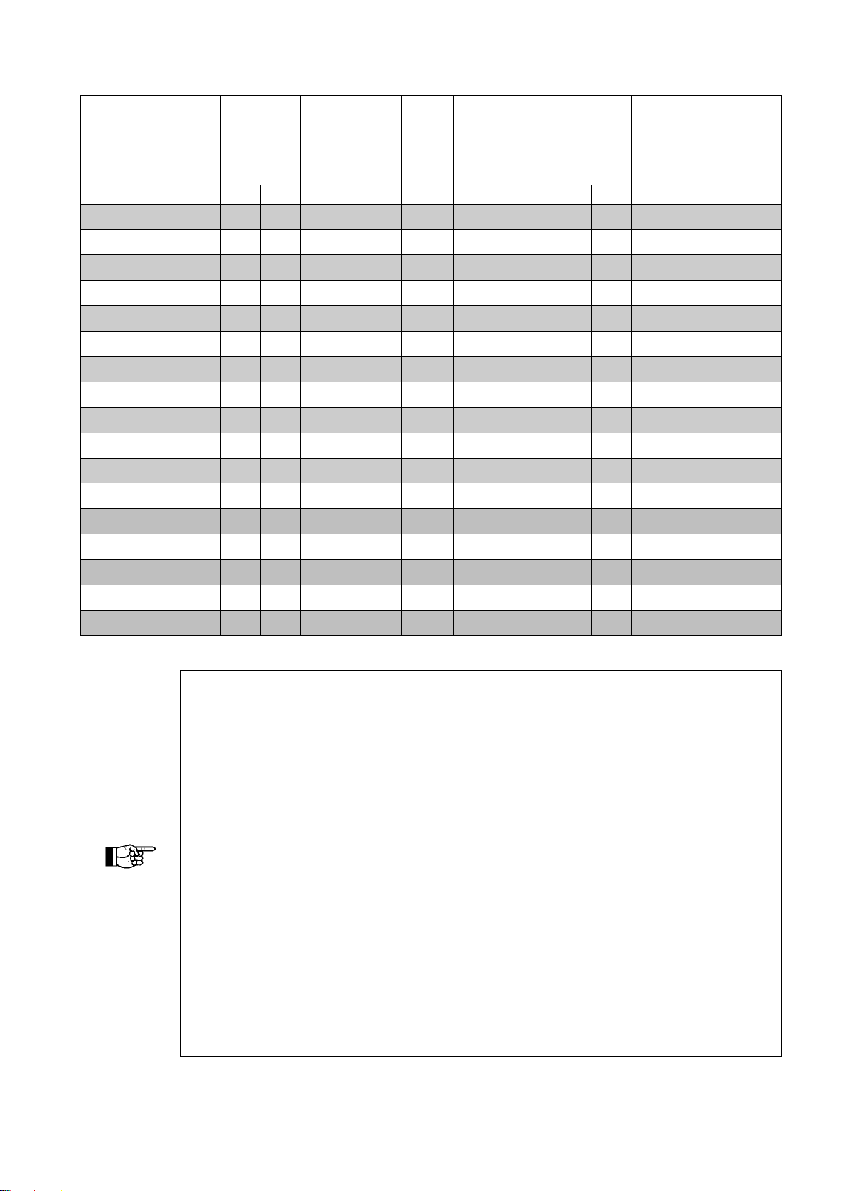
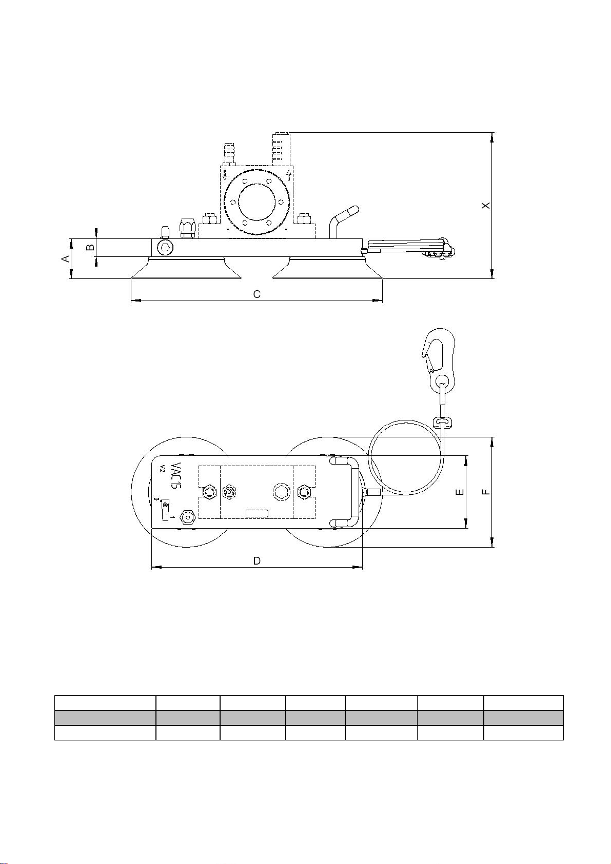
NetterVibration VAC 8 User manual

Assembly and Operating Instructions Oct. 2014
Netter Vacuum-Fixing-Devices BA Nr. 1555E
Page 1/24
These operating instructions apply for: VAC 8
VAC 10
VAC 11
VAC 12
VAC 13
VAC 15
VAC 20
VAC 30
VAC 40

2
Table of Contents
1GENERAL NOTES 3
2SAFETY 5
3TECHNICAL DATA 7
4DESIGN AND FUNCTIONING 12
5TRANSPORT AND STORAGE 13
6INSTALLATION 14
7START-UP / OPERATION 21
8SERVICE / MAINTENANCE 22
9TROUBLESHOOTING 23
10SPARE PARTS 24
11ACCESSORIES 24
12WASTE DISPOSAL 24
13ENCLOSURES 24
Scope of delivery
The VAC are delivered with the following
components as standard:
Vacuum fixing device (VAC)
Operating instructions
Packaging
From series VAC 11 safety rope
For changes to the scope of delivery
please refer to the delivery note.
Check the packaging for possible signs of
transport damage. In the event of damage
to the packaging, check that the contents
are complete and undamaged. If there is
any damage, inform the shipping agent.
Compare the scope of the delivery with the
delivery note.

3
1 General notes
Information on the operating instructions
Use and storage of the operating
instructions
Before use of the Vacuum fixing device of
the series VAC read this operating manual
carefully. It is the basis for any action taken
with regard to the VAC and may be used
for training purposes. The operating
manual should subsequently be stored
near the VAC.
Target group
The target group of these operating
instructions is qualified technical personnel
from the mechanical engineering sector
who have a basic knowledge of pneumatics
and mechanics.
Installation, commissioning, maintenance,
fault elimination and disassembly of the
VAC must only be performed by persons
who have been instructed in the proper
handling of the units.
Persons who have not been instructed
accordingly must not carry out any works
on the VAC.
Copyright
This documentation is subject to copyright.
All rights e.g. for translation, photo-mechanical
reproduction, printing or reproduction (e.g.
data processing, data carriers and data
networks) of this operating manual, or parts
thereof, are strictly reserved to
kÉííÉêVibration.
Limitation of liability
A
ll technical information, data and
instructions on installation, operation and
maintenance in these operating instructions
are based on the latest information
available at the time of printing and take
into account our past experience to the best
of our knowledge.
No claims can be derived from the
information, illustrations and descriptions in
these operating instructions.
The manufacturer does not assume liability
for damages resulting from:
failure to observe the operating
instructions
improper use
unauthorized repairs
technical modifications
use of inadmissible spare parts
Translations are made to the best
knowledge. kÉííÉêVibration does not
assume liability for translation errors, even
if the translation was made by us or on our
behalf. Only the original German version is
binding.

4
The following instruction and warning symbols are used in these operating instructions.
DANGER referring to a possible risk, which, if not avoided, can
result in death or serious injury.
CAUTION referring to a possible risk, which, if not avoided, can
result in serious injury and/or equipment damage.
IMPORTANT note with especially useful information and tips.
ENVIRONMENTALLY
FRIENDLY
DISPOSAL
refers to the obligation of an environmentally friendly
disposal
Information on the VAC
Netter vacuum fixing devices of series
VAC for pneumatic vibrators are in strict
compliance with the EC Machine Di-
rective 2006/42/EC. The standard DIN
EN 12100 has been observed in particu-
lar.
Special features
Quick mounting without bolting or
welding
Strong connection due to high vacuum
Can also be used on curved and une-
ven surfaces
optional air economizer

5
2 Safety
Designated use:
Vacuum fixing devices of series VAC are
used for quick fastening of vibrators to
smooth and, to a limited extent, also to
rough and curved surfaces.
They are used in combination with vibra-
tors for the emptying of transport contain-
ers or drums, for the cleaning of pipes etc.
Vacuum fixing devices are used where
conventional fastening methods for vibra-
tors fail, frequent relocation of vibrators is
required and welding or bolting is not pos-
sible.
Any other use is considered improper use.
There are no built-in safety devices.
Qualification of the personnel:
Assembly, start up, maintenance and
repair of the impactors must be
performed only by authorized qualified
personnel.
Any handling of the pneumatic impactors
lies within the responsibility of the opera-
tor.
Accessories which ensure the correct
operation and safety must provide a
protection type required for the specific
use.
CAUTION
kÉííÉêVibration does not assume liability for damage or injury resulting
from technical modifications to the product or failure to observe the
instructions and warnings in this operating manual.
CAUTION
Not every pneumatic vibrator is suitable to the vacuum fixing device. Applicable
vibrators are listed in chapter 6 „Mounting of vibrator and hose set“.
When choosing a different vibrator a preceding consultation is required.
DANGER
Source of danger:
In case of an unexpected pressure drop the vacuum
fixing devices may come loose.
Possible consequences of non-observance:
A fixing device dropping down can cause bodily injury
and/or damage to property.
Avoiding the danger:
The vacuum fixing devices VAC 8 and VAC 10 are by
customer secured against drop down.
From series VAC 11 the vacuum fixing devices are
fitted with an adjustable safety rope. This rope must
be pre-tensioned as short as possible using a bulldog
grip. Should a vacuum fixing device come loose it
should never drop into a slack rope.

6
DANGER
Source of danger:
Faulty hose connections.
Possible consequences of non-observance:
Apressurized hose coming loose can cause se-
vere injury.
Avoiding the danger:
The hose lines must be securely connected. This
must be checked at regular intervals and the
screw connections have to be retightened if nec-
essary.
DANGER
Source of danger:
Vibrators bolted to vacuum fixing devices may
come loose by the effect of vibration.
Possible consequences of non-observance:
Falling parts can cause damage to persons and
material.
Avoiding the danger:
Screw retention components and/or Loctite or
similar must be used. Screw connections must
be checked and, if necessary, retightened after
1 hour of operation and then at regular intervals
(normally every month).
Jan. / Feb. / ...
DANGER
Source of danger:
With parts of smaller cross section there is a risk
that a vacuum fixing device may come loose.
Possible consequences of non-observance:
A fixing device dropping down can cause bodily
injury and/or damage to property.
Avoiding the danger:
The vacuum fixing device must not be mounted
on round components, which have a smaller di-
ameter than permitted in chapter 3 “Technical
data“.
CAUTION
Source of danger:
In the vicinity of the VAC 13-40 the noise level
can exceed 80 dB(A).
Possible consequences of non-
observance:
Human hearing can be permanently damaged
by the high noise level.
Avoiding the danger:
When working in the noise area, ear defenders
are required if the sound level exceeds 80 dB(A).

7
3 Technical data
Type Generated
vacuum
[bar]=
Generated
suction
power*
[N]=
Weight
[kg]=
A
ir
consump-
tion
[l/min]=
Noise
level**
[dB(A)]=
recommended
minimum diameter
for
round containers
[mm]
4 bar6 bar 4 bar 6 bar 4 bar 6 bar 4 bar 6 bar
VAC 8 + HG 10 N 0,60 0,85 340 481 0,95 40 60 68 75 110
VAC 8 + HG 10 S 0,60 0,85 340 481 1,20 20 22 68 75 110
VAC 10 + HG 10 N 0,60 0,85 465 658 1,05 40 60 68 75 110
VAC 10 + HG 10 S 0,60 0,85 465 658 1,30 20 22 68 75 110
VAC 11 + HG 10 N 0,60 0,85 710 1.005 1,25 40 60 74 78 110
VAC 11 + HG 10 S 0,60 0,85 710 1.005 1,50 20 22 74 78 110
VAC 12 + HG 15 N 0,60 0,85 1.250 1.770 2,85 60 122 64 79 350
VAC 12 + HG 15 S 0,60 0,85 1.250 1.770 3,20 29 36 64 79 350
VAC 13 + HG 15 N 0,60 0,85 1.362 1.930 4,20 110 170 83 77 850
VAC 13 + HG 15 S 0,60 0,85 1.362 1.930 4,55 41 52 83 77 850
VAC 15 + HG 15 N 0,60 0,85 1.476 2.091 3,40 110 170 83 89 650
VAC 15 + HG 15 S 0,60 0,85 1.476 2.091 3,75 41 52 83 89 650
VAC 20 + HG 15 N 0,60 0,85 2.724 3.859 7,25 110 170 79 79 850
VAC 20 + HG 15 S 0,60 0,85 2.724 3.859 7,60 41 52 79 79 850
VAC 30 + HG 30 N 0,60 0,85 4.086 5.789 11,50 110 170 79 79 1.500
VAC 30 + HG 30 S 0,60 0,85 4.086 5.789 12,00 49 60 79 79 1.500
VAC 40 + HG 40 N 0,60 0,85 5.448 7.718 20,00 220 340 82 86 1.500
* Maximum suction power at 5 bar. For operation of a vibrator a higher pressure may be required.
**The noise level was measured at a distance of 1 m without vibrator. The noise level of vibrators may be higher.
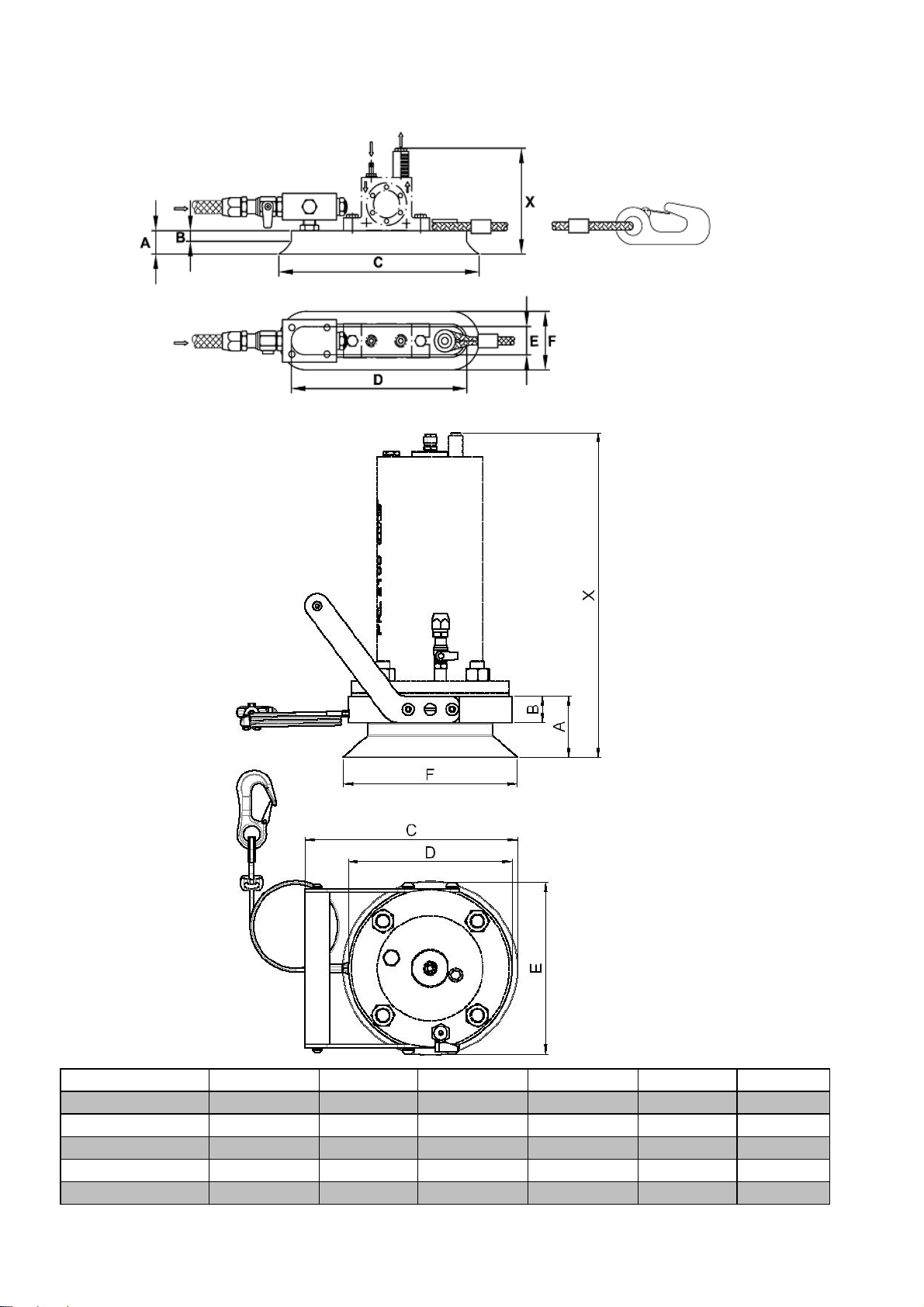
IMPORTANT
Admissible operating conditions
Drive medium
Clean (Filter 5 µm, quality class 3 according to DIN ISO 8573-1), com-
pressed air or nitrogen.
Unfiltered air will cause damage to the mounted vibrators.
Lubrication
VAC fixing devices do not require lubrication.
For the mounted vibrator lubricated compressed air may be specified. Please
refer to the corresponding operating instructions for the vibrator.
Operating pressure
4 bar to 6 bar*
Operating pressures must not be exceeded or fall short of.
Ambient temperature
-10°C to 60°C
The admissible ambient temperatures must not be exceeded or fallen short of
during operation.
*) Higher operating pressures and temperatures are only permitted after consultation and written confirmation by
application engineers of kÉííÉêVibration.

8
Dimensions:
VAC 8 / VAC 10 / VAC 11 / VAC 12
VAC 13
Type A B C D E F
VAC 8 19 8 150 127 30 55
VAC 10 22 8 200 175 26,5 55
VAC 11 20 5,5 300 276 26 55
VAC 12 25 10 300 268 68 100
VAC 13 70 30 186 241 195 197
All dimensions in [mm] - measurement X depending on vibrator

9
VAC 15 / VAC 20
All dimensions in [mm] - measurement X depending on vibrator
Type A B C D E F
VAC 15 50 25 345 290 100 150
VAC 20 70 30 425 370 150 200

10
VAC 30
Type A B C D E F
VAC 30 70 30 396 339 426 370
All dimensions in [mm] - measurement X depending on vibrator

11
VAC 40
Type A B C D E F
VAC 40 70 25 426 375,5 425 370
All dimensions in [mm] - measurement X depending on vibrator

12
4 Design and Functioning
Vacuum fixing device
A vacuum fixing device mainly consists of a base
plate, a 2/2-way ball valve, a vacuum nozzle and
suction cups. When operating the 2/2-way ball valve
the vacuum nozzle generates a vacuum. By this the
suction cups of the vacuum fixing device adheres to
the mounting surface by suction.
Functional unit
Hose set, vacuum fixing device and vibrator togethe
r
form a functional unit. The vibrator is tightly bolted to
the vacuum fixing device. Vibrator and vacuum fixing
device are supplied with the necessary energy (com-
pressed air or nitrogen) through the hose set.
The hose set is normally available in two different designs:
Hose set "Standard" HG .. N and hose set "Economy Air Supply" HG .. S:
Hose set HG ... N
The vacuum fixing device (opened main valve - cus-
tomer) will always be under pressure, when the
pressure is applied.
The vibrator is switched on and off by actuation of
the manually operated 3/2-way slide valve.
Hose set HG ... S
In addition to the standard function (see hose set
"Standard" HG .. N) the hose set „Economy Air
Supply“ HG .. S has an economy switch position.
With the vibrator switched off the compressed air
consumption can be reduced by approx. 30% in
comparison to the standard version by means of a
throttle. This compressed air reduction makes
sense, because the "holding function" does not re-
quire the totally available compressed air. The total-
ly available compressed air is only needed for op-
eration of the vibrator.
Hose set HG with throttle control valve
Both versions of the hose-sets (N and S) are
available with throttle control valve (DRV) and
recommended by kÉííÉêVibration.
Means of this valve, the pressure which is ap-
plied to the vibrator may be adjusted. Thus, there
is the possibility of the speed of the vibrator and
the impact frequency of the vibrator to adjust.
vibrator
VAC
hose set
Connection
between hose set
and compressed
air source
suction cups
(in this example 2x)
2/2-way ball valve
vacuum nozzle
VAC
vibrator
vibrator
VAC
DRV
throttle control valve
throttle
DRV
VAC
VAC
vibrator
vibrator
3/2-way slide valve
3/2-way slide valve

13
5 Transport and Storage
IMPORTANT
Check the packaging for possible signs of transport damage. In the event of
damage to the packaging, check that the contents are complete and undamaged.
If there is any damage, inform the shipping agent.
Packaging
The vacuum fixing devices are packaged
ready for commissioning. The type desig-
nation is stamped (8 VAC, VAC 10, VAC
11, VAC 12 and VAC 13) or engraved
(VAC 15 VAC 20 VAC 30 and VAC 40) on
the base plate.
When ordering a vacuum fixing device with
hose set and vibrator these components
are completely assembled, unless other-
wise agreed. Special transport conditions
are not prescribed.
The packaging protects the unit from
transport damages. The packaging materials
have been selected on an environmental
and disposal-friendly basis and are there-
fore recyclable.
Recycling packagings reduces raw material
consumption and waste volume.
Storage
Protect the vacuum fixing devices from
excessive exposure to UV radiation,
weathering and ozone.
The vacuum fixing devices should be
stored in boxes in a dry and clean envi-
ronment. When restocking all openings
must be closed.
The storage temperature should be
between -10 and +25°C. (This does not
apply to the operating temperature).
After 4 years of storage all plastic and sili-
cone components must be replaced before
using.

14
6 Installation
CAUTION
Make sure the compressed air supply is
switched off during installation or any other
work on vacuum fixing devices, vibrator or air
supply lines.
Complete vacuum fixing devices with hose
set and vibrator are directly ready for oper-
ation after connection to compressed air.
If ordered separately, hose set and vibrator
must first be assembled.
.
The following vibrators can be mounted to the vacuum fixing devices:
Type Suitable vibrators
NCB NCR NCT NTK NTS NTP PKL
VAC 8 +HG 10 N 1, 2 1, 2 8AL,15X, 120 HF, 120 NF* 25**
VAC 8 +HG 10 S 16, 18AL 180 HF, 180 NF*
VAC10+HG 10 N 1, 2, 3 3 3, 4 15X,
18AL 180 HF, 180 NF* 25** 190**
VAC10+HG 10 S 250 HF, 250 NF*
VAC11+HG 10 N 3, 5 10 5, 10 18AL 180 HF, 180 NF 190**
VAC11+HG 10 S 250 HF, 250 NF 450**
VAC12+HG 15 N 10, 20 22 15, 29 25AL 350 HF, 350 NF
100/01, 75/01**, 50/01**
25**,
32**,
48**
450**
VAC12+HG 15 S 740**
VAC13+HG 15 N 10, 20 22 15, 29 75/01, 50/01, 70/02* 32** 740, 2100
VAC13+HG 15 S 5000
VAC15+HG 15 N 10, 20 22 15, 29 18AL, 25 250 HF,250 NF,350 HF,350 NF 32, 48* 740
VAC15+HG 15 S 50, 70 57* 55, 108* 75/01, 50/01, 70/02*
VAC20+HG 15 N 57 55, 108 70/02, 54/02, 50/04* 32, 48 2100
5000
VAC20+HG 15 S
VAC30+HG 30 N 120 126,
250
50/04, 50/08*
NVG 49,
55, 61 5000
VAC30+HG 30 S NVG 82,
84*
VAC40+HG 40 N 50/08*, 50 /10*
*Depending on application, please consult kÉííÉêVibration.** Adapter plate required, please add to your order!
DANGER
Not every pneumatic vibrator is suitable for the vacuum fixing device. With drill pat-
terns different to the ones for the above listed units the internal pilot bores may be
damaged. The above mentioned combinations (fixing device/vibrator) have been
tested and can be used without any limitations.
When choosing a different vibrator a prior consultation is required.
Use screw retentions and nuts to fasten the vibrator. Use a liquid screw retention
agent (e.g. Loctite) against loosening. (If you use a VAC with a PKL, it must be
mounted with the prescribed NBS fixing kit!)
Use tightening torques according to the following table.
Higher tightening torques may cause fracture of screws or tearing of threads. In-
adequate screw connections may cause loosening of units by vibration.
This can cause damage to persons and material!

15
Recommended mean tightening torques for screws of quality 8.8
(screws as supplied, without additional lubrication):
Thread Tightening torque [Nm] Thread
Tightening torque [Nm]
M 6 10 M 12 80
M 8 23 M 16 190
M 10 48 M 20 380
IMPORTANT Vibrators must be cautiously and properly fastened. The fastening screws for the
vibrator must be retightened or checked after 1 operating hour.
VAC 8, VAC 10, VAC 11 and VAC 12
Installation of the Vibrator:
In order to mount vibrators
NCT two tapped blind holes
must be drilled.
If a compressed air operated
piston vibrator of series NTS
or NTK is to be mounted, we
recommend the use of an
adapter plate.
Alternatively one hole must be
drilled into the suction cup and
the tapped hole sealed with a
suitable sealing agent.
For the size Xrefer to the op-
erating instructions for the re-
spective vibrator.
IMPORTANT
When drilling blind holes make sure not to drill through the suction cup (rubber).
However, if this should happen, you must seal the tapped holes with a suitable seal-
ing agent, as otherwise no vacuum can be generated.
ada
p
ter
p
late
rubbe
r
rubbe
r
rubbe
r

16
VAC 13, VAC 15, VAC 20, VAC 30 and VAC 40
Installation of the Vibrator:
In order to mount the vibrator to a VAC 13,
VAC 15 or VAC 20 socket head cap
screws acc. to DIN 7991 are required. The
assembly can be performed as follows:
1. Unscrew the suction cups.
2. Determine and mark the necessary bore
holes (commonly used bore pitches
have already been marked with a centre
punch, see template VAC 15 and VAC
20).
3. Drill through-holes (diameter depending
on type of vibrator - see operating in-
structions for vibrator).
Countersink bores from bottom side of
base plate (side of suction cup) acc. to
DIN 74-Bf....
4. Fasten the vibrator using the specified
socket head cap screws. For this pur-
pose use common screw retentions.
5. Assemble the suction cups in the correct
position.
IMPORTANT For assembly of the PKL 740 to the VAC 15 an adapter plate is required, if the
inlay EE is not used.
Template VAC 13
Do not drill through
this aerea!

17
Template VAC 15
Template VAC 20
Do not drill through
this aerea!
Do not drill through
this aerea!
R
ou
n
d
Pl
a
t
e
Round Plate

18
Template VAC 30
VAC 40
Installation of the Vibrator:
The VAC 40 consists of two VAC 20, which
are connected by an adapter plate. The
vibrator is mounted to the adapter plate.
For the fastening of a compressed air op-
erated piston vibrator series NTS 50/10 the
adapter plate has four through holes. For
the fastening of any other vibrator you
should consult kÉííÉêVibration beforehand.
Installation of the VAC on the lifting device
Due to its own weight, the vacuum fixing
device may only be lifted with suitable lifting device. When lifting the vacuum fixing de-
vice an eyebolt M16 is available.
Do not drill through
this aerea!

19
Vacuum fixing devices should be used in combination with the following hose sets:
Type Hose set (except PKL) Hose set for PKL
VAC 8 HG 10 N or HG 10 S
VAC 10 HG 10 N or HG 10 S
VAC 11 HG 10 N or HG 10 S HG 10 N or HG 10 S
VAC 12 HG 15 N or HG 15 S HG 10 N or HG 10 S
VAC 13 HG 15 N or HG 15 S HG 10 N or HG 10 S
VAC 15 HG 15 N or HG 15 S HG 10 N or HG 10 S
VAC 20 HG 15 N or HG 15 S HG 10 N or HG 10 S
VAC 30 HG 30 N or HG 30 S HG 10 N or HG 10 S
VAC 40 HG 40 N
Throttle control valves (DRV) are recommended for use of a hose set.
Example of Hose set HG N with DRV
Example of Hose set HG S with DRV
connection
Compressed
air supply
connection
Compressed
air supply
connection
Vibrator
connection
Vacuum fixing
devices
connection
Vacuum fixing
devices
connection
Vibrator
Manual slide valve DRV
throttle screw
(air economizer function)

20
Connection of power supply
Supply line:
The pressure loss increases with the hose
length. The following recommendations re-
fer to hose lengths of max. 3 m to the next
bigger hose cross section. For longer
supply lines we recommend the use of big-
ger cross-sections, whereby the supplied
hose socket can no longer be used.
Minimum cross-sections for hoses
CAUTION A too small cross-section does not enable a sufficient vacuum.
Type Hose socket Hose size
HG 10 N / S 1/4“ NW 6
HG 15 N / S 3/8“ NW 9
HG 30 N / S 1/2“ NW 12
HG 40 N 1/2“ NW 12
Safeguard with safety rope
DANGER
Before mounting locate a secure attachment point (e.g.
an eye bolt) where you can hook the safety rope of the
vacuum fixing device to attach it on your container or
your construction.
This rope must be pre-tensioned as short as possible
by using a rope clamp.
Should a vacuum fixing device come loose it must not
drop into a slack rope.
Checklist for installation:
1)
2)
3)
4)
5)
6)
7)
Install the vibrator. Mounting screws secure.
Install hose set.
Install maintenance unit (filter, regulator and lubricator possibly) and
valve.
Lock the fastening screws with glue (e.g. Loctite).
Glue the air supply lines.
Observe the information on hose length and diameter.
Connect safety cable!
This manual suits for next models
9
Table of contents
Other NetterVibration Industrial Equipment manuals

NetterVibration
NetterVibration NVV Series User manual

NetterVibration
NetterVibration NED 605 User manual

NetterVibration
NetterVibration VAC Series User manual

NetterVibration
NetterVibration PKL Series User manual

NetterVibration
NetterVibration NTP Series User manual

NetterVibration
NetterVibration NEG Series User manual

NetterVibration
NetterVibration NTP Series User manual

NetterVibration
NetterVibration NTS Series User manual

NetterVibration
NetterVibration NWE Series User manual