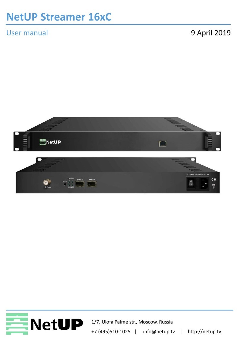
NetUP Streamer User manual

NetUP Streamer.
User’s manual

2
Contents
1Introduction
Intended audience . . . . . . . . . . . . . . . . . . . . . . . . . . . . . . . . . . . . . . . . . . . . . . . . . . 3
Notation conventions . . . . . . . . . . . . . . . . . . . . . . . . . . . . . . . . . . . . . . . . . . . . . . . . 3
About NetUP Streamer . . . . . . . . . . . . . . . . . . . . . . . . . . . . . . . . . . . . . . . . . . . . . . 3
Numbering of NetUP Streamer inputs . . . . . . . . . . . . . . . . . . . . . . . . . . . . . . . . . . . 4
All-in-one solution from NetUP . . . . . . . . . . . . . . . . . . . . . . . . . . . . . . . . . . . . . . . . 4
2LCD panel
Introduction . . . . . . . . . . . . . . . . . . . . . . . . . . . . . . . . . . . . . . . . . . . . . . . . . . . . . . . 5
Statistics screen. . . . . . . . . . . . . . . . . . . . . . . . . . . . . . . . . . . . . . . . . . . . . . . . . . . . 5
Set IP address and subnet mask. . . . . . . . . . . . . . . . . . . . . . . . . . . . . . . . . . . . . . . 5
Generate new administrator’s password . . . . . . . . . . . . . . . . . . . . . . . . . . . . . . . . . 6
3Web interface
Overview . . . . . . . . . . . . . . . . . . . . . . . . . . . . . . . . . . . . . . . . . . . . . . . . . . . . . . . . . 7
How to get started? . . . . . . . . . . . . . . . . . . . . . . . . . . . . . . . . . . . . . . . . . . . . . . . . . 7
Streaming . . . . . . . . . . . . . . . . . . . . . . . . . . . . . . . . . . . . . . . . . . . . . . . . . . . . . . . . 9
IPTV. . . . . . . . . . . . . . . . . . . . . . . . . . . . . . . . . . . . . . . . . . . . . . . . . . . . . . . . . . . . 19
System administration . . . . . . . . . . . . . . . . . . . . . . . . . . . . . . . . . . . . . . . . . . . . . . 20
System configuration . . . . . . . . . . . . . . . . . . . . . . . . . . . . . . . . . . . . . . . . . . . . . . . 21
System status . . . . . . . . . . . . . . . . . . . . . . . . . . . . . . . . . . . . . . . . . . . . . . . . . . . . 24
4System maintenance
Backup copies . . . . . . . . . . . . . . . . . . . . . . . . . . . . . . . . . . . . . . . . . . . . . . . . . . . . 26
Editing IP table rules . . . . . . . . . . . . . . . . . . . . . . . . . . . . . . . . . . . . . . . . . . . . . . . 26
Network troubleshooting . . . . . . . . . . . . . . . . . . . . . . . . . . . . . . . . . . . . . . . . . . . . 27
NetUP server troubleshooting . . . . . . . . . . . . . . . . . . . . . . . . . . . . . . . . . . . . . . . . 27
NetUP server factory reset . . . . . . . . . . . . . . . . . . . . . . . . . . . . . . . . . . . . . . . . . . 27

3
Introduction
3
Intended audience
This manual is intended for IPTV service providers using NetUP solutions. An overall knowledge of TV broadcasting
systems and IP networking is assumed. The document covers basic functionality of device, recommendations for its
configuration and operation.
Notation conventions
About NetUP Streamer
NetUP Streamer allows to receive and relay streams from the following sources:
–satellites;
–terrestrial antennas;
–cable networks;
–IP providers;
–streams of Internet broadcasting;
–IP cameras;
–storage.
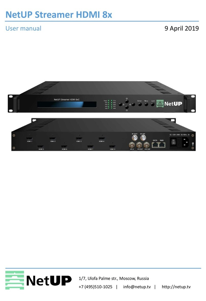
Headend stations NetUP Streamer are presented in three models:
– NetUP Streamer mini – the compact headend station allows to receive streams from 4 satellite transponders and
relay 50 or more channels;
– NetUP Streamer 8x – the station for TV providers which allows to receive streams from 8 satellite transponders and
relay 100 or more channels with the total speed of over 900Mbps;
– NetUP Streamer 16x – the station for TV providers which has redundant power supply and hot-swap storage and
allows to receive streams from 16 satellite transponders and relay 200 or more channels.
Additional features requires a separate license. To purchase the license, please contact the NetUP managers.
Code blocks;
Notes
Warnings related to incomplete compatibility with older versions of NetUP.tv NetUP.tv
Generic warnings
NetUP Streamer may be supplied with additional features: transcoding and content encryption before
broadcasting and create a mosaic channel

4
Numbering of NetUP Streamer inputs
Numbering of NetUP Streamer inputs
Inputs located on the rear panel of NetUP Streamer and numbered as follows:
All-in-one solution from NetUP
NetUP Streamer may use as a stand-alone solution and as part of the NetUP IPTV Combine.
NetUP IPTV Combine is an unique all-in-one device. It includes all the tools necessary for the operator:
– Middleware – provides communication between content sources and customer’s TV set-top boxes.
– Billing – manages the customer base and commercial services.
–Streamer – receives and relays content to a local network or the Internet.
– VoD/TVoD server – stores content.
NetUP IPTV Combine, similar to NetUP IPTV Streamer, is represented by three models:
– IPTV Combine mini – a compact station for networks serving up to 50 customers, with full functionality;
– IPTV Combine 8x – an Ideal solution for networks serving up to 500 customers, for example, for hotels, cruise
liners;
– IPTV Combine 16x – a productive solution for large companies.
To know more information about NetUP IPTV Combine, please contact the NetUP managers.
Adapter
1
0
CAM
0
0
1
1
NetUP Streamer mini
1
0
3
2
1
0
Adapter
10CAM
1
1
0
0
Adapter
1
0
CAM
0
0
1
1
NetUP Streamer 8x
3
2
1
0
7
6
5
4
Adapter
10CAM
1
0
1
0
1
0
1
0
CAM
1
0
1
0
1
0
1
0
Adapter
10
NetUP Streamer 16x

5
LCD panel
4
Introduction
In order to set up the NetUP’s server equipped with LCD panel, do the following:
1. Plug the network and power cables into the device.
2. Switch power on. You shall see Startup... on the LCD panel.
3. Use the LCD manager for the initial setup of the system.
Statistics screen
Among other items, the LCD menu contains two statistics screens. The default screen displays the network adapters
traffic transfer rate. The lower line of the screen presents the total rate of input and output traffic separated by “/”.
Use Up and Down buttons to navigate through menu elements. Press Up to switch to the CPU load screen.
First number is the total CPU load. Three subsequent numbers give, correspondingly, the portions of CPU load related
to user tasks (u), system tasks (s), and awaiting data from the peripherals (w). Press Down to return to the traffic
statistics screen.
Press Down to navigate to the rest of menu items:
– Reboot system – restart server
– Shutdown system – shutdown server
– Generate (Reset) password – generate a new admin password
Set IP address and subnet mask
1. Select the Network setup screen and press Enter to go to settings menu.
2. Press Up and Down to select the network interface and press Enter.
3. If you need to edit IP address press Enter and then press Up or Down to select an octet for editing. The selected
octet will be indicated by a symbol " > ".
4. Select the last octet of the IP address and press Enter to go to edit the subnet mask.. Press Up or Down to
increase or decrease the number of mask bits. Press Enter to go to the save settings dialog.
5. Select Save changes to save the IP address and the mask and select Discard to cancel settings. Buttons Up and
Down switch between options, with currently selected option emphasized with brackets. Press Enter to confirm
the selection.
6. When the settings are done, set up your DNS server (via its config file) to associate the IPaddress just entered with
mw.iptv domain name.
LCD manager provides a convenient way to monitor the CPU and LAN interface load on the device front panel,
as well as to assign IP addresses to network adapters.
Generate password allows to reset the administrator’s password. The new administrator’s password is
displayed on the LCD until a key is pressed on the front panel
< IPTV [I/0]^ >
12.0 / 0.55 Mbps
< IPTV [CPU]v >
20% 0u 20s 0w
UP
Select interface
Interface 1
IP address:
> 10. 2. 0. 12
Enter

6
Generate new administrator’s password
Generate new administrator’s password
1. Starting from the statistic screen, press Up until you see the Reset Password.
2. Press Enter to generate new password and apply it to all system components. The password will be displayed on
the LCD screen.

7
Web interface
5
Overview
Web interface is used for setting up various server parameters and client's STBs.
To access the web interface, enter an IP address of Middleware server in your browser's address bar. On the opened
page enter the login and the password specified in the equipment passport.
The left panel of the web interface contains links to settings pages, pages are organized into groups. The presence of
pages and groups depends on the hardware configuration of the server and the privileges of the currently logged in
system user.
For the NetUP Streamer server administrator, the web interface includes:
How to get started?
1. Open the DVB to IP gateway page (the Streaming group) in the web interface.
It is strongly recommended to change the password immediately after logging in for the first time. For more info,
see Security on page 23
Group Page Function
Streaming DVB to IP gateway Control the NetUP Streamer, see CAM module parameters, set up
transponders and output streams
IPTV SNMP agents Set up SNMP, download the MIB file
System
administration
Files Download the Administrator’s Guide
Power Management Reboot and shutdown server
Update Update firmware
Status Get info about the services
Backup Manage backup
System
configuration
Network Manage network interfaces and VLANs
Routing Manage user routing rules
Security Change the admin password
Date and time Select timezone and set up server time
Licence Download licenses
System status About Get info about components, license and server hardware
Connections Get info about NetUP.tv systems
Storage Get info about disk space usage

8
How to get started?
2. Click Expand input on an input panel. If the input signal is not configured or turned off, the expanded panel
displays only adapter settings. If the input signal is enabled, click Expand input settings to show the adapter
settings panel.
3. Set the input parameters in one of the following ways:
– manually – select Input mode (DVB-S, DVB-S2, DVB-T, DVB-T2, DVB-C Annex A, ISDB-T) and fill in all the
parameters. Each of Input modes has its own set of parameters, and the list of available modes depends on the
DVB adapter type. For more info, see Input modes on page 13
– get settings from satellite database or browse network – click on the Get transponder settings button on
the right and select the option: Satellite database or Browse network. In the opened window select one of the
available transponders to fill in its parameters in the form
– upload settings from preset – click Select a preset and choose one from the list. The preset settings will be
displayed in the form. If necessary, you can change parameter values.
4. Check the Enable input box.
5. Click on Apply button to active the settings. As a result, the panel displays input signal quality indicators and the
list of programs for the selected frequency.
Browse network is available for DVB-S and DVB-S2
Changing parameter values in the web form does not affect the preset. For more info, see Configure an input
using a preset on page 14
If you use a preset to set up an input, click on Apply and choose one of the actions: Apply input settings or
Apply both input and streaming settings, because the preset can store not only the parameters to configure
the input, but also the parameters to configure output streams.
If the preset stores only the parameters to configure the input, the panel displays the Load button

9
Streaming
Streaming
DVB to IP gateway
This page displays all available inputs. Each input has its own panel.
If an Input is enabled, the panel displays mode and frequency of the input stream, signal decoding information, and
CAM name.
If an Input is not enabled, the panel displays Input is stopped.
The following actions are available on the page:
1. Tune the page interface
Click on the Interface options button and select Settings. In the opened window, enable or disable the available
options and click Close. For more info, see Interface options on page 10
2. Get channel list
Click on the Interface options button and select Get channel list. In the opened window, select a format: XML or
M3U, and click Download or Copy.
3. Get EPG
Click on the Interface options button and select Get EPG. In the opened window, select a format: JSON or
XMLTV,and click Download or Copy link to EPG.
4. Expand the panel with input settings
Left-click on the corresponding button on the input panel you want to configure. For more info, see Input panel on
page 10
Inputs in the web interface are numbered as inputs on the rear panel of the NetUP Streamer (see Streamer on
page 2)

10
Streaming
Interface options
Click the button in the upper-right corner of the DVB to IP gateway page to open the Interface options window and
enable / disable the following options:
– Edit streams for one program in a single dialog – enable the option if you want to set up all output streams for
one program in a single common window. For more info, see Set up streaming on page 18.
– Display no more than two destinations for each service in the services list – enable the option if you want
to display no more than two destinations for each service in the common list of services in the input panel.
– Show failed to unscramble warnings – disable the option if you want to hide warnings about decoding errors
on the NetUP DVB to IP gatewaypage.
– Use MSym/s as symbol rate units – enable the option if you want to switch symbol rate units. Default symbolic
speed is in KSym/s.
– Enable interface tutorial – enable the option if you want to run a short tutorial on NetUP DVB to IP gateway.
– Interface language – select English or Russian for the interface.
Input panel
Click Expand input on an input panel to access its settings.
If you have already configured the signal for the selected input, the expanded input panel displays:
–Signal quality indicators

11
Streaming
–Input settings
–CAM parameters
–Programs and streams
If the input signal is not set or turned off, the expanded input panel only includes transponder settings. How to configure
the input signal, see How to get started? on page 7.
Signal quality indicators
Click Expand input on an input panel to see quality indicators
If the input is enabled, there are the following indicators:
–Signal – denotes presence of the signal (red means no signal);
– Carrier – denotes presence of the carrier frequency (red means no carrier);
–FEC – denotes the error correction;
–Sync – denotes synchronization with the signal;
–Lock – means that the adapter has locked on the signal and is decoding it successfully;
– PSI – program specific information: PAT, PMT, SDT, NIT, EIT, and etc. Click on the indicator to see more;
–SNR – signal to noise ratio;
–BER – bit error rate;
– Statistics – transport stream statistics. Click on the indicator to see more;
– Signal strength – signal strength in percent.
The status of the indicators changes after each update of the input signal parameters.
Input settings
Click Expand input settings to access to the settings.
The following actions are available on the panel:
1. Upload input and streaming settings from a preset
Select a preset from the list and the web form displays the parameters stored in the preset. If necessary, you can
Click on the pencil icon under the input number, write ‘Input name’ and save it.

12
Streaming
change parameter values.
At the bottom of the panel, click Apply and select Apply input settings to upload only input settings, or select Apply
both input and streaming settings to load the input settings first and then click Load to upload the streaming settings
from the same preset.
2. Save or edit a preset
Set the parameters to configure the input and click Apply. If necessary, set up streaming settings, then select from
the preset list New preset and click Save preset. In the opened window write the preset name and click Save.
Select a preset from the preset list, modify input settings and / or streaming settings, apply changes and click Save
preset. In the opened window edit the preset name, if necessary, and click Save.
3. Delete a preset
Select the preset from the list and click Delete preset.
4. Import or export a preset
Click Other actions and select Import. In the opened window select a file and click Open.
Select a preset from the list, click Other actions and select Export. The preset will be uploaded to a file.
5. Set transponder parameters manually
Select Input mode (DVB-S, DVB-S2, DVB-T, DVB-T2, DVB-C Annex A, ISDB-T), set all parameters manually and
click Apply.
6. Get transponder settings
Click Get transponder settings and select one of available lists: Satellite database or Browse network. In the
opened window, select one of available transponders to fill in the form using its parameters.
7. Enable or disable an input
Check or uncheck the corresponding flag on the input panel and click Apply.
Changing parameter values in the web form does not affect the preset. To find out how to modify a preset,
please see Configure an input using a preset on page 14
Input settings and streaming settings from the same preset are downloaded separately.
If the preset stores only input settings, the panel displays Load. If a preset stores input and streaming settings,
the web form displays Apply
The preset stores input and streaming settings. Read more here How to get started? on page 7
For more info, see Create and edit a preset on page 13
Deleting a preset does not affect the broadcasting. A set of preset settings is used only to quickly fill out web
forms
Exporting and importing templates is done in json format
Each of Input modes has its own set of parameters, and the list of available modes depends on the DVB adapter
type. For more info, see Input modes on page 13
Browse network is available for DVB-S and DVB-S2

13
Streaming
Input modes
PLP (Physical Layer Pipe) is a logical channel that may carry one or multiple services. You can specify the ID of the
channel that you want to receive in the corresponding field.
Create and edit a preset
1. Open the DVB to IP gateway page (the Streaming group) in the web interface.
2. Click Expand input on an input panel and then click Expand input settings.
3. Select the New preset from the preset list.
4. Fill in the transponder parameters manually or by selecting from the available list (for more info, see How to get
started? on page 7), set up other input parameters and click on Apply. As a result, the panel displays input signal
quality indicators and the list of programs for the selected frequency.
After disabling the input, all output streams will be automatically disabled. After re-enabling the input, all output
streams that were set up before disabling will be automatically enabled
Input mode Parameter Description
DVB-S/DVB-S2 Frequency The signal frequency
Symbol rate The rate of symbol transfer
Polarization Vertical / Right, Horizontal / Left or Disabled
LNB type Dual Ku band, Single Ku band, С band. Once it is selected, the
corresponding values of LNB parameters appear in their fields
LNB low frequency The LO frequency for the low-frequency range of satellite signal.
See the hardware specifications for particular values
LNB high frequency The LO frequency for the high-frequency range of satellite signal
LNB switch frequency The border between satellite signal frequency ranges
Port group A, B, C, D or off
Tone Enables controlling the LNB by feeding a special 22 kHz tone to it
DVB-C Annex A Frequency The signal frequency
Modulation QAM 16, QAM 32, QAM 64, QAM 128, QAM 256 or Auto
Symbol rate The rate of symbol transfer
DVB-T/DVB-T2 Frequency The signal frequency
Modulation QPSK, QAM 16, QAM 64 or Auto
Transmission mode 1К, 2К, 4К, 8К, 16К, 32К or Auto
Bandwidth 8MHz, 7MHz or 6MHz
Guard interval 1/32, 1/16, 1/8, 1/4 or Auto
For DVB-S2 and DVB-T2, the Select PLP option is available
See the description of web interface pages here: DVB to IP gateway on page 9and Input settings on page 11

14
Streaming
5. Set up streams and then save the preset. Parameters of all configured streams will be saved into the preset. For
more info, see Set up streaming on page 18
6. Click on Save preset. In the opened window write Preset name and click Save.
7. If you need to edit a preset, select the preset from the list, change settings for the input or the streaming or both,
apply the changes and then click Save preset. In the opened window, you can save changes and rename the
preset.
Configure an input using a preset
1. Open the DVB to IP gateway page (the Streaming group) in the web interface.
2. Click Expand input on an input panel. If the input signal is not configured or turned off, the expanded panel
displays only adapter settings. If the input signal is enabled, click Expand input settings to show the adapter
settings panel.
3. Select a preset from the list and the web form displays the parameters saved in the preset. If necessary, you can
change parameter values.
4. Click Load or Apply => Apply input settings to active the settings from the preset. As a result, the panel displays
input signal quality indicators and the list of programs for the selected frequency.
5. Click Apply => Apply input settings and the bottom part of the panel will display the streams which were saved in
the preset.
If you only need to save the input settings in the preset, skip this step
See the description of web interface pages here: DVB to IP gateway on page 9and Input settings on page 11
Changing parameter values in the web form does not affect the preset. To find out how to modify a preset,
please see Create and edit a preset on page 13
If a preset stores only input settings, the web form displays Load. If a preset stores input and streaming settings,
the web form displays Apply
Input settings and streaming settings from the same preset are downloaded separately
When loading the streaming settings, the system compares addresses of the existing streams with stream
addresses that need to be downloaded from the selected preset. If the system finds identical addresses, it will
generate an error and stop broadcasting streams that were downloaded from the preset

15
Streaming
6. Check the stream addresses and change their settings or enable streams manually. To do it, open the Stream
setup window, select a stopped stream, change its Address, check the Enable stream box and click Apply.
CAM parameters
Click Expand input on an input panel to see the CAM parameters:
–CAM status or name
–RM (Resource manager)
–AI (Application information)
–CA (Conditional Access Support)
–MMI (Man-Machine Interface)
–Menu (CAM settings)
–Messages
Click on RM, AI, CA indicator to see more details about CAM.
For more info, see Set up streaming on page 18
If CAM is not enabled, the panel displays only “CAM: missing”
Click MMI to close MMI session

16
Streaming
Programs and streams
Click Expand input on an input panel to see the list of received programs and to set up streams.
The following actions are available on the panel:
1. Open program properties
Click on a Program number to see program properties.
2. Open the program schedule for the near future
Click on a Program name to see the names of the program that is on the air and the next one.
3. Test descrambling
Click on the corresponding button, then select programs in the opened window, and click Test. The test results will
be displayed opposite each of the programs.
4. Hide idle services
Click on the corresponding button on the panel, now only programs with active streams are shown. Click on this
button again to show all programs.
5. Copy an output stream address
Click on the copy icon next to the stream address. If the program has more than one output stream, click the copy
icon and select the address you want to copy If the stream is one, it will be copied immediately after clicking.
6. Set up streaming
Click on the corresponding button opposite of the program you want to set up output streams for. In the opened
Stream setup window, add and configure required number of streams, then click Apply and close the window.
Added streams will appear in the program list in the column Destination.
You can see the list of received programs, if you have configured the input signal. How to configure the input
signal, see Web interface: Stream setup on page 17
This option is available for encrypted streams. If the lock is closed, the stream is encrypted. If the lock is opened,
the stream is decrypted
The description of the Stream setup window is in the next section. See an example of setting up a stream here
How to get started? on page 7

17
Streaming
Stream setup
On the input panel, opposite the required program, click on the button in the Streaming column to open the Stream
setup window. The window is divided into two parts: Streams list and Stream settings.
The following actions are available in the window:
1. Copy an output stream address
Click on the copy icon next to the stream address. The stream address will be copied to clipboard.
2. Delete an output stream
Move the mouse over the line with the stream you want to delete and the Action column will display the delete icon.
Click on this icon and the State column will display the appropriate mark. Click Back to uncheck the mark or click
Apply to delete the selected stream (streams).
3. Add a stream
Click Add stream and set the stream parameters. Click Apply to save the added stream (streams).
4. Configure stream settings
Add a stream or select the existing one with the left mouse button and make sure that the Stream settings panel
displays the required stream ID. Select the stream Type and fill in the parameter fields. Each type of stream has its
Edit streams for one program in a single dialog, if the corresponding option is enabled in the interface settings
(see Interface options on page 10).

18
Streaming
own set of parameters. Then check PIDs and service tables (NIT, SDT, EIT) that you want to include in the stream.
If necessary, change settings of other streams and click Apply to save changes.
Set up streaming
1. Open the DVB to IP gateway page (the Streaming group) in the web interface.
2. Click Expand input on an input panel. If necessary, configure the input. For more info, see How to get started?
on page 7
3. In the program list, opposite the program, in the Streaming column, click on the button to open the Stream setup
window.
4. In the opened window, in the Stream settings, select a stream Type and set up the other parameters. Each type of
stream has its own set of parameters.
5. Mark flags in front of PIDs and service tables (NIT, SDT, EIT) that you want to include in the stream.
In the Stream list, the State column displays the pencil icon for streams which have been edited and the plus
icon for streams which have been added.
See the description of web interface pages here: DVB to IP gateway on page 9and Input settings on page 11
The Stream setup window is divided into two parts: Stream list and Stream settings

19
IPTV
6. Click Add stream, if you need to add another stream for the selected program, and repeat the steps number
4 and 5.
7. Click Apply, if you want to save changes or click Close to close the window without saving changes.
8. If you want to edit a stream, click on a line with stream’s parameters in the Streams list to select one and make
changes in the Stream settings. The State column in the Streams list displays a pencil opposite the stream that
has been changed. Click Apply, if you want to save changes or click Close to close the window without saving
changes.
IPTV
SNMP agents
This page contains the list of communities entitled to make SNMP requests.
The following actions are available on the page:
1. Download MIB file
Click Download MIB-file to get the .txt file. The NetUP’s MIB file contains a template for the following information:
If you need to add several streams of the same type for one program, we recommend adding a two-digit
number in the Address field to the last digit in the fourth octet, which is one more than the previous one,
for example, if the address of the 1st stream is 235.114.3.1, then for the 2nd stream, the address can be
235.114.3.1 01, and for the 3rd one – 235.114.3.1 02. In this case it is easier to avoid IP address conflict
Edit streams for one program in a single dialog, if the corresponding option is enabled in the interface settings
(see Interface options on page 10).
netupCpuTable containing information about every CPU (core) in the system
netupCpuEntry an element that describes each row of the table and combines elements:
netupCpuIndex the CPU number
netupCpuLoad the CPU load level
netupCpuTemp the CPU temperature
netupStreamerTable containing information about every streamer in the system
netupStreamerTableEntry an element that describes each row of the table and combines elements:
adapterNumber the adapter number
netupBER the bit error rate
netupSNR the signal to noise ratio
netupLOCK the signal lock status
netupStorageTable containing information about every hard drive in the system
netupStorageTable an element that describes each row of the table and combines elements:
netupStorageIndex the storage number
netupStorageDevice the path to the storage (for example,
"/dev/sda1")
netupStorageMountPoint the mounting point of the storage (for example,
"/mnt/hdd")
netupStorageFilesystem the file system of the storage

20
System administration
2. Add an agent
Click Add agent, then in the opened window, fill in the fields and click Save.
3. Edit parameters of a community or delete it
Left-click on the community’s IP address. In the opened window make changes and click Save to apply them or
click Delete to remove the community.
System administration
Files
Here you can download the “NetUP.tv Administrator's Guide” in Russian or English.
Power Management
Here you can Reboot and Shutdown the server. Whenever the server needs to be reloaded or shut down, this should
be done exclusively by means of these controls; abnormal termination may lead to system failure.
Update
This page allows to update the firmware. This page lists the uploaded firmware files together with their uploading dates,
build numbers, and possible actions. Click a firmware to open detailed information popup: Delete or Install.
Connect to the server via ftp (use login update and administrator’s password). Refresh the page, select the uploaded
file from the list and click Install.
netupStorageBlockSize the block size on the storage
netupStorageFragmentSize the fragment size on the storage
netupStorageSize the storage size
netupStorageFree the free space on the storage
For the system as a whole:
netupMemPhisTotal the total memory size
netupMemPhisFree the free memory size
netupMemPhisBuffers the buffer size
netupMemPhisCached the cache memory size
netupMemSwapTotal the maximum size of the swap file
netupMemSwapFree the free space within the swap file
netupStbClients the number of connected STB clients
netupPcClients the number of connected PC clients
netupTotalClients the total number of connected clients
To request all available parameters, download the MIB file, pass it to the SNMP daemon, and run the following
command: snmpwalk -v2c -c netuptest 10.1.0.77 NETUP-MIB::netup
Incompatible firmware versions are recognized and displayed in the list as damaged files
netupStorageTable containing information about every hard drive in the system
Table of contents
Other NetUP Media Player manuals
