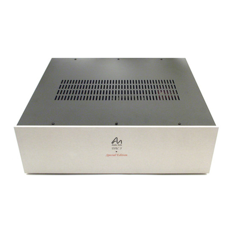
Network Electronics SDI-EO-D15 Series User manual

Rev. 1
Network Electronics ASA, Hinderveien 4, 3204 Sandefjord, Norway, Tel.:+47 33 48 99 99 Fax: +47 33 48 99 98
E-mail: [email protected] - Web: http://www.network-electronics.com
Technical specifications are subject to be changed without notice
1
USER MANUAL
SDI-EO-D15xx.xx
SDI Fiber Optical Converter
for
Dense Wavelength Division Multiplexing
(DWDM)
Network Electronics ASA
Hinderveien 4
N-3204 Sandefjord, Norway
Phone: +47 33 48 99 99
Fax: +47 33 48 99 98
e-mail: [email protected]
www.network-electronics.com

SDI-EO-D-15xx.xx Rev. 1
Network Electronics ASA, Hinderveien 4, 3204 Sandefjord, Norway, Tel.:+47 33 48 99 99 Fax: +47 33 48 99 98
E-mail: [email protected] - Web: http://www.network-electronics.com
Technical specifications are subject to be changed without notice
2
Revision history
The latest version is always available in pdf-format on our web-site:
http://www.network-electronics.com/
Current revision of this document is the uppermost in the table below.
Revision Replaces Date Change Description
1 0 02.01.08 RS T622-EO-D15xx.xx no longer available
0C01.05.08 RS Product release
C B 01.03.23 RS Included information on the T622-EO-D15xx.xx module
BA01.03.20 RS Added correct LED status
A-01.03.09 RS Initial Revision

SDI-EO-D-15xx.xx Rev. 1
Network Electronics ASA, Hinderveien 4, 3204 Sandefjord, Norway, Tel.:+47 33 48 99 99 Fax: +47 33 48 99 98
E-mail: [email protected] - Web: http://www.network-electronics.com
Technical specifications are subject to be changed without notice
3
Index
Revision history.................................................................................................................................................2
1. General............................................................................................................................................................4
2. Specifications .................................................................................................................................................5
3. Connector module.........................................................................................................................................6
3.1 Applying signals to the connector module.............................................................................................6
4. Module status ................................................................................................................................................7
4.1 GPI – Module Status Outputs.................................................................................................................7
4.2 Front Panel - Status Monitoring............................................................................................................8
5. Laser safety precautions ..............................................................................................................................9
Declaration of conformity with CE ...............................................................................................................10
General environmental requirements for flashlink®equipment.............................................................10
Notes..................................................................................................................................................................11

SDI-EO-D-15xx.xx Rev. 1
Network Electronics ASA, Hinderveien 4, 3204 Sandefjord, Norway, Tel.:+47 33 48 99 99 Fax: +47 33 48 99 98
E-mail: [email protected] - Web: http://www.network-electronics.com
Technical specifications are subject to be changed without notice
4
1. General
Equalizer
Distribution Amplifier
Optical Transmitter
SDI Input
143-
540Mbps
Optical
Output
2 x SDI
Output
Figure 1 : Block diagram of the processes inside the SDI-EO-D-15xx.xx.
The flashlink SDI to Optical converter for DWDM is a multi bit rate converter module for use together
with the SDI-EO-C1 connector module. The unit can handle bit rates from 143Mbps up to 540Mbps. An
on-board cable equaliser provides up to 35dB gain at 200 MHz. This will typically result in equalisation of
more than 300 m of high quality coax cable at 270Mbps. The optical output is made with a DFB laser for
wavelengths according to ITU-T rec. G.692. The products are not sold separately, but as parts of a
flashlink®DWDM-system.
The product is available in 16 versions:
Part number Wavelength Part number Wavelength
SDI-EO-D1549.32
SDI-EO-D1552.52
SDI-EO-D1555.75
SDI-EO-D1558.98
1549.32nm laser
1552.52nm laser
1555.75nm laser
1558.98nm laser
SDI-EO-D1550.92
SDI-EO-D1554.13
SDI-EO-D1557.36
SDI-EO-D1560.61
1550.92nm laser
1554.13nm laser
1557.36nm laser
1560.61nm laser
SDI-EO-D1530.33
SDI-EO-D1533.47
SDI-EO-D1536.61
SDI-EO-D1539.77
1530.33nm laser
1533.47nm laser
1536.61nm laser
1539.77nm laser
SDI-EO-D1531.90
SDI-EO-D1535.04
SDI-EO-D1538.19
SDI-EO-D1541.35
1531.90nm laser
1535.04nm laser
1538.19nm laser
1541.35nm laser

SDI-EO-D-15xx.xx Rev. 1
Network Electronics ASA, Hinderveien 4, 3204 Sandefjord, Norway, Tel.:+47 33 48 99 99 Fax: +47 33 48 99 98
E-mail: [email protected] - Web: http://www.network-electronics.com
Technical specifications are subject to be changed without notice
5
2. Specifications
Inputs
SDI data rate NRZ: 143Mbps – 540Mbps
Equalisation: Auto. up to 35dB
Impedance: 75 ohm
Return loss >15dB @270MHz
SDI signal level: nom. 800mV
Connector BNC
Electrical
Power: +5V DC
Control: Control system for access to set-up and module
status with BITE (Built-In Test Equipment).
Electrical Output
Number of outputs: 2
Connector: BNC
Impedance: 75 ohm
Return loss: > 15dB @270MHz
Signal level SDI: nom. 800mV
Rise/fall time: typ. 650ps
Optical Output
Transmission circuit fiber: Single Mode
Light source: DFB Laser
Optical power: 0 dBm
Optical center wavelength: According to ITU-T rec. G.692
Max. wavelength drift ±0.32nm
Jitter (UI=unit interval): 0.135 UI max. @ 270 Mbps
Return loss Better than 40 dB typ.
Maximum reflected power: 4%
Connector SC/PC acc. to SMPTE 259M

SDI-EO-D-15xx.xx Rev. 1
Network Electronics ASA, Hinderveien 4, 3204 Sandefjord, Norway, Tel.:+47 33 48 99 99 Fax: +47 33 48 99 98
E-mail: [email protected] - Web: http://www.network-electronics.com
Technical specifications are subject to be changed without notice
6
3. Connector module
The SDI-EO-D15xx.xx has the same connector module as the SDI-EO: SDI-EO-C1.
This module is mounted at the rear of the sub-rack.
The module is shown in figure 2.
Figure 2. Overview of the SDI-EO-C1 connector module
3.1 Applying signals to the connector module
The connector module is the same for the SDI-EO-D and the SDI-OE cards.
Apply the SDI signal to the BNC digital input connection. For monitoring purposes there are two
digital outputs as well. These signals have a loop-through function where the SDI signal applied at the
digital input is equalised and passed through a distribution amplifier to the two digital outputs. The signal
is the same at both outputs.
The optical connection is an SC/UPC connector with a return loss better than 40dB typ.
According to the specification SMPTE 259M, the return loss shall be better than 26 dB.

SDI-EO-D-15xx.xx Rev. 1
Network Electronics ASA, Hinderveien 4, 3204 Sandefjord, Norway, Tel.:+47 33 48 99 99 Fax: +47 33 48 99 98
E-mail: [email protected] - Web: http://www.network-electronics.com
Technical specifications are subject to be changed without notice
7
4. Module status
The status of the module can be monitored in three ways.
1. GYDA-SC controller.
2. GPI at the rear of the sub-rack.
3. LED's at the front of the sub-rack.
Of these three, the GPI and the LED's are mounted on the module itself, whereas the GYDA-SC controller
is a separate module giving detailed information of the status of the card. The functions of the GPI and the
LED's are described in sections 4.1 and 4.2. The GYDA-SC controller is described in a separate user
manual.
4.1 GPI – Module Status Outputs
These outputs can be used for wiring up alarms for third party control systems. The GPI outputs are open
collector outputs, sinking to ground when an alarm is triggered. The GPI connector is shown in figure 2.
Electrical Maximums for GPI outputs
Max current: 100mA
Max voltage: 30V
SDI-EO-C1 GPI pinning:
Signal Name Pin # Mode
Status General error status for the module. Pin 1 Open Collector
LOS Electrical input signal is missing. Pin 2 Open Collector
Laser Fail Laser Fail Alarm Pin 3 Open Collector
Ground 0 volt pin Pin 8 0V.
Figure 3: GPI Outlet

SDI-EO-D-15xx.xx Rev. 1
Network Electronics ASA, Hinderveien 4, 3204 Sandefjord, Norway, Tel.:+47 33 48 99 99 Fax: +47 33 48 99 98
E-mail: [email protected] - Web: http://www.network-electronics.com
Technical specifications are subject to be changed without notice
8
4.2 Front Panel - Status Monitoring
The status of the module can be easily monitored visually by the LED's at the front of the module. The
LED's are visible through the front panel as shown in figure 4.
(Text not printed on the front panel).
Figure 4 Diode overview of SDI-EO-D
The SDI-EO-D has 3 LED's each showing a status corresponding to the GPI pinning. The position of the
different LED's is shown in figure 4.
Diode \ state Red LED Green LED No light
Status Module is faulty Module is OK
Module power is OK Module has no power
LOS Loss of signal
No electrical input signal. Electrical input signal
present
Laser fail Laser is malfunctioning Laser is OK

SDI-EO-D-15xx.xx Rev. 1
Network Electronics ASA, Hinderveien 4, 3204 Sandefjord, Norway, Tel.:+47 33 48 99 99 Fax: +47 33 48 99 98
E-mail: [email protected] - Web: http://www.network-electronics.com
Technical specifications are subject to be changed without notice
9
5. Laser safety precautions
Guidelines to limit hazards from laser exposure.
All the available EO units in the flashlinkrange include a laser.
Therefore this note on laser safety should be read thoroughly.
The lasers emit light at 1310 nm or 1550 nm. This means that the human eye cannot see the beam, and the
blink reflex can not protect the eye. (The human eye can see light between 400 nm to 700 nm).
A laser beam can be harmful to the human eye (depending on laser power and exposure time), therefore:
!! BE CAREFUL WHEN CONNECTING / DISCONNECTING FIBER PIGTAILS (ENDS).
NEVER LOOK DIRECTLY INTO THE PIGTAIL OF THE LASER/FIBER.
NEVER USE MICROSCOPES, MAGNIFYING GLASSES OR EYE LOUPES TO LOOK INTO A
FIBER END.
USE LASER SAFETY GOGGLES BLOCKING LIGHT AT 1310 nm AND AT 1550 nm.
Instruments exist to verify light output power: Power meters, IR-cards etc.
Flashlinkfeatures:
The FR-2RU-10-2 is classified as Class 1 laser product according to EN 60 825-1:94/A11:96, and
CFR Ch1(1997) Part 1040.10.
If the front panel is removed, the FR-2RU-10-2 is classified as Class 1 laser product according to
EN 60 825-1:94/A11:96, and classIIIb according to CFR Ch1(1997) Part 1040.10.
Maximum output power: 5 mW.
Operating wavelengths: 1310 nm or 1550 nm.
< 5mW
>1270nm

SDI-EO-D-15xx.xx Rev. 1
Network Electronics ASA, Hinderveien 4, 3204 Sandefjord, Norway, Tel.:+47 33 48 99 99 Fax: +47 33 48 99 98
E-mail: [email protected] - Web: http://www.network-electronics.com
Technical specifications are subject to be changed without notice
10
Declaration of conformity with CE
This apparatus meets the requirements of EN 55103-1 (November 1996) with regard to emissions, and EN
55103-2 (November 1996) with regard to immunity; it thereby complies with the Electromagnetic
Compatibility Directive 89/336/EEC.
General environmental requirements for flashlink®equipment
1. The equipment will meet the guaranteed performance specification under the following environmental
conditions:
•Operating room temperature range 0°C to 40°C
•Operating relative humidity rangeup to 90% (non-condensing)
2. Electromagnetic compatibility conditions:
•Emissions EN 55103-1 (Directive 89/336/EEC)
•Immunity EN 55103-2 (Directive 89/336/EEC)

SDI-EO-D-15xx.xx Rev. 1
Network Electronics ASA, Hinderveien 4, 3204 Sandefjord, Norway, Tel.:+47 33 48 99 99 Fax: +47 33 48 99 98
E-mail: [email protected] - Web: http://www.network-electronics.com
Technical specifications are subject to be changed without notice
11
Notes
This manual suits for next models
16
Table of contents
Other Network Electronics Media Converter manuals
Network Electronics
Network Electronics ADC-SDI User manual
Network Electronics
Network Electronics ADC-SDI-CC User manual

Network Electronics
Network Electronics Flashlink HD-OE-2 User manual
Network Electronics
Network Electronics HD-EO User manual
Network Electronics
Network Electronics Flashlink ETH1000-D User manual
Network Electronics
Network Electronics Flashlink ETH1000MC User manual
Network Electronics
Network Electronics Flashlink HD-EO-2 User manual
Network Electronics
Network Electronics Flashlink ETH100 User manual
Network Electronics
Network Electronics Flashlink SDI-EO-2 User manual

