NetworX Architech Guide

1
ArchiTech Cylindrical Lock & Surface-Mounted Networx Control Unit Mounting and Installation Instructions
ArchiTech™by Networx™
FOR CYLINDRICAL LOCKS USING SURFACE-MOUNTED NETWORX CONTROL UNITS
MOUNTING AND INSTALLATION INSTRUCTIONS
© NAPCO Security Technologies, Inc. 2016 WI2104B 09/16
DESCRIPTION
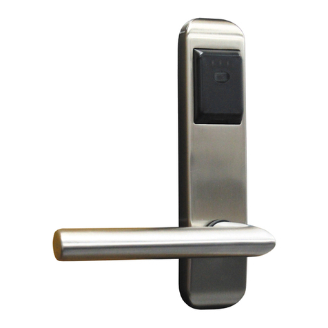
These instructions detail the hardware installation procedure for the ArchiTech cylindrical door locks using the Surface
-Mounted Networx Control Units for hollow metal and solid wood doors.
Installation instructions for the Door Contact Sensor, Door Contact Magnet (installed in the door jamb) and the
Oval and Rectangular Proximity Readers are also included.
PARTS OVERVIEW
For reference, the images in Fig. A display each component (not to scale). In addition to the various screws and tem-
plates included with your lock, please note that one of two types of Proximity Readers are included, either Oval or
Rectangular. In addition, one of two types of Door Contact Magnets (installed in door jamb) are included, ei-
ther 3/8" or 3/4" diameter.
Wires for the Door Contact Sensor, Proximity Reader and Cylindrical Lock motor are routed through the door
and are plugged into the rear of the Surface-Mounted Networx Control Unit, mounted on the inside ("protected")
door surface.
The Cylindrical Lock Motor Wire can be routed within hollow metal doors; with solid wood doors, this Cylindrical Lock
Motor Wire can be routed on the door surface but behind a Wiring Plate (HW1945), or an optional Cylindrical
Drill Jig (part #N90S1DJ) is available to allow a hole to be drilled allowing this wire to be routed through the
solid wood door.
REQUIRED TOOLS
In addition to the standard door prep kit tools used to install a cylindrical lock into a metal or wood door (standard ASA
161 door prep cross-bore hole saws, Phillips and flat head screwdrivers, etc.), you will need: A small level, and the
following drill bit sizes: 5/8", 3/8", 3/4" and 7/64". If the Cylindrical Drill Jig (part #N90S1DJ) is used, a round or cir-
cular file is needed to remove burrs in holes and to file a pathway groove in wooden doors for the Cylindrical
Lock Motor Wire.
IMPORTANT: For installation on UL Listed Wood Fire Doors, fill the through hole wire passage with UL Clas-
sified Fire Stop Sealant after connecting all wiring and testing the Lock.
FIG. A: OVERVIEW OF BASIC PARTS (NOT TO SCALE)
"SURFACE-MOUNTED" NETWORX
CONTROL UNIT
AND ITS MOUNTING PLATE
OVAL AND RECTANGULAR
PROXIMITY READER COVERS AND
MOUNTING COMPONENTS
USE WIRING PLATE (LEFT)
OR OPTIONAL CYLINDRICAL
DRILL JIG (RIGHT)
OR
DOOR CONTACT
MAGNET
(TWO TYPES)
OR
DOOR
CONTACT
SENSOR

ArchiTech Cylindrical Lock & Surface-Mounted Networx Control Unit Mounting and Installation Instructions
2
DOOR PREP: INITIAL STEPS
1. INSPECT THE DOOR BEVEL
Inspect the door for a bevel and, if beveled, determine which side is "longer" in width and which side is "shorter" in
width (see "top view" example in Fig. 1). For beveled doors, be sure to use the correct marks printed on the template
for the correct length of the outside door surface (either the "long" or "short" side of the door).
2. PREP DOOR FOR CYLINDRICAL LOCK
If not done already, use standard door prep kit tools and the instructions included with the cylindrical lock to prep the
door and door jamb as required (standard ASA 161 door prep). These include the 5/16" and 2-1/8" thru-holes, the 1"
latch hole and mortising the door edge for the latch plate and mortising the door jamb for the strike plate.
Do not install the lock hardware yet.
DOOR 3½° bevel
Door Stop
Arc of door swing
Jamb
"Shorter side of
door"
"Longer side of
door"
FIG. 1: EXAMPLE OF BEVELED DOOR (TOP VIEW)
FIG. 2: USE TEMPLATE PROVIDED

3
ArchiTech Cylindrical Lock & Surface-Mounted Networx Control Unit Mounting and Installation Instructions
3. TAPE ON DOOR: "PROXIMITY READER" TEMPLATE (WI2098)
Remember, the Proximity Reader is always located on the outside
("unprotected" side) door surface.
Fold and place the template (WI2098) on the outside door edge (see arrow
in Fig. 3 for an example). Align the template with the "HORIZONTAL CEN-
TER LINE OF LEVER" as shown on the template. Tape the template in
place.
4. MARK TEMPLATE "PROXIMITY READER" HOLES
On the outside door surface, mark the two holes for the Proximity Reader mounting screws.
Mark the center of the 5/8" diameter thru-hole (used for the Cylindrical Lock Motor Wire, Proximity Reader and Door
Contact Sensor wires).
TIP: Take special notice of this 5/8" diameter thru-hole, as it is an essential hole for this installation and is refer-
enced several times throughout these instructions.
FIG. 3: EXAMPLE OF OUTSIDE DOOR
EDGE (ARROW)
FIG. 4. CLOSE UP OF WI2098 TEMPLATE FOR THE "PROXIMITY READER"

ArchiTech Cylindrical Lock & Surface-Mounted Networx Control Unit Mounting and Installation Instructions
4
5. MARK TEMPLATE "DOOR CONTACT SENSOR" HOLE
Mark the 3/4" Door Contact Sensor hole in the edge of the door for the correct door thickness.
Carefully remove the template.
6. MARK "DOOR CONTACT MAGNET" ON JAMB
The Door Contact Magnet must be installed in the door jamb such that when the door is closed, the Door Contact Sen-
sor is located directly opposite the Magnet. Install as follows:
6A.Open the door and temporarily place a piece of tape across the center of the mark made for the Door Contact
Sensor in the previous step. This tape signifies the height (from the floor) of the Door Contact Sensor.
6B.Close the door. Transfer this height to the door jamb with a light pencil mark.
6C.Determine the center location on the jamb directly opposite the Door Contact Sensor when the door is closed.
Open the door and measure the distance from the door edge to the center of the Door Contact Sensor (0.875"
or ⅞"). Transfer this distance to the door jamb, measured from the door stop.
FIG. 5: DOOR CONTACT SENSOR HOLE
ON DOOR EDGE
FIG. 5A: SELECT HOLE FOR DOOR THICKNESS
FIG. 6B: CLOSE DOOR AND
TRANSFER HEIGHT TO JAMB
FIG. 6A: TAPE SIGNIFIES
"HEIGHT FROM FLOOR" FIG. 6C: LOCATE MAGNET IN JAMB
CENTERED DIRECTLY OPPOSITE THE
SENSOR WHEN DOOR IS CLOSED

5
ArchiTech Cylindrical Lock & Surface-Mounted Networx Control Unit Mounting and Installation Instructions
7. TAPE ON DOOR: "SURFACE-MOUNTED NETWORX CONTROL UNIT"
TEMPLATE (WI2099)
The Surface-Mounted Networx Control Unit (see Fig. A on page 1) is al-
ways mounted on the inside ("protected") door surface.
Fold and place the template (WI2099) on the inside door edge. Align the
template with the "HORIZONTAL CENTER LINE OF LEVER" and the 5/8"
diameter thru-hole as shown on the template. Tape the template in place.
8. MARK TEMPLATE "SURFACE-MOUNTED NETWORX CONTROL UNIT" HOLES
On the inside ("protected") door surface, mark the two Control Unit Mounting Plate (Fig. 8) holes using the correct mark-
ings printed on the template (if door is beveled, use correct markings for beveled doors as described in step 1).
The center of the 5/8" diameter thru-hole was already marked on the outside surface in step 4; for the inside door sur-
face, mark the center of the 5/8" diameter thru-hole. This 5/8" diameter thru-hole is used for the Cylindrical Lock Motor
Wire, Proximity Reader and Door Contact Sensor wires.
Carefully remove the template.
FIG. 7: EXAMPLE OF INSIDE
DOOR EDGE (ARROW)
FIG. 8: MARK THE TWO "CONTROL UNIT
MOUNTING PLATE" HOLES (ARROWS)

ArchiTech Cylindrical Lock & Surface-Mounted Networx Control Unit Mounting and Installation Instructions
6
DOOR PREP: DRILL HOLES
IMPORTANT: Remove all burrs from wire holes. Sharp edges can eventually wear away wire insulation.
9. DRILL THE FOLLOWING HOLES IN THE DOOR
9A. Use 7/64" drill bit:
On the outside ("unprotected side")
door surface, drill the two pilot
holes for the Proximity Reader
mounting screws (NOT thru-holes,
drill only into the door surface).
9B. Use 7/64" drill bit:
On the inside ("protected side")
door surface, drill the two pilot
holes for the Control Unit Mounting
Plate mounting screws (NOT
thru-holes). Drill only into the in-
side door surface.
9C. Use 5/8" drill bit: 5/8"diameter thru-hole.
Drill straight through the door.
9D. Use 3/4" drill bit: 3/4" Door Contact
Sensor hole in edge of the door
(for solid wood doors, drill until the
hole intersects with the 5/8" diameter
thru-hole).
FIG. 9A: 7/64" PILOT HOLE ON
OUTSIDE DOOR SURFACE FOR
PROXIMITY READER
FIG. 9B: 7/64" PILOT HOLE ON
INSIDE DOOR SURFACE FOR
CONTROL UNIT PLATE
FIG. 9C:
5/8" DIAMETER THRU-HOLE
(5/8" DIAMETER
THRU-HOLE,
DRILLED IN
STEP 9C)
(CYLINDRICAL
LOCK PREP,
STEP 2)
"DOOR CONTACT SENSOR" HOLE
(3/4") IN EDGE OF DOOR
FIG. 9D: 3/4" DOOR CONTACT SENSOR HOLE IN EDGE OF THE DOOR

7
ArchiTech Cylindrical Lock & Surface-Mounted Networx Control Unit Mounting and Installation Instructions
10. DRILL "DOOR CONTACT MAGNET" HOLE IN JAMB
10A. Find the Door Contact Magnet. The type provided will be either Type A or Type B (see image below). For the
type provided, note its dimensions in Fig. 10A.
10B. Drill into the door jamb as follows:
For Hardwood Jambs:
For the thicker "Type A" contact (below left image): Drill a 3/4" hole 7/8" deep into the jamb (marked in
step 6).
For the thinner "Type B" contact (below right image): Drill a 3/8" hole 7/8" deep into the jamb (marked
in step 6).
For Hollow Metal Jambs:
Use either a 3/4" or 3/8" bit (depending on Door Contact Magnet Type A or Type B) to drill a hole into the sur-
face of the jamb.
10C. Insert the magnetic Door Contact Magnet in the jamb hole; the contact sits almost flush with the jamb when fully
inserted. In some cases, an adhesive may be needed to ensure a secure fit.
FIG. 10A: FIND THE "DOOR CONTACT MAGNET" PROVIDED, EITHER
TYPE A (3/4" DIAMETER) OR TYPE B (3/8" DIAMETER)
Φ31/32" Φ7/16"
Type A (3/4" dia.) Type B (3/8" dia.)
FIG. 10B: DRILL DOOR JAMB HOLE
(EITHER 3/8" OR 3/4" DEPENDING
ON TYPE)
FIG. 10C: DOOR CONTACT MAGNET
INSTALLED IN DOOR JAMB

ArchiTech Cylindrical Lock & Surface-Mounted Networx Control Unit Mounting and Installation Instructions
8
DECISION: HOW TO ROUTE THE CYLINDRICAL LOCK MOTOR WIRE?
The Cylindrical Lock Body includes a Cylindrical Lock Motor Wire plug that must be
routed to and plugged into the Surface-Mounted Networx Control Unit.
HOW this Motor Wire is routed depends on whether the door is solid or hollow, and
whether you choose to use the Wiring Plate HW1945 (wires routed behind plate) or
the Cylindrical Drill Jig part #N90S1DJ (wires routed through door).
Hollow Metal Doors:
Option 1: (Easiest option) Route the Cylindrical Lock Motor Wire
within the hollow metal door. Skip to step 12E on page 13.
Option 2: If for some reason you do not wish to run wires through a
hollow metal door, route the Cylindrical Lock Motor Wire behind the Wir-
ing Plate (HW1945). The wire runs along one of its inside grooves
that, when installed, rests against the inside door surface. Skip to step
11.
Solid Wood Doors:
Option 1: Route the Cylindrical Lock Motor Wire behind the Wiring
Plate (HW1945) along one of its grooves that, when installed, rests
against the inside door surface. Skip to step 11.
Option 2: If you do not wish to use the Wiring Plate, use the Cylin-
drical Drill Jig (part #N90S1DJ) to drill a pathway for the wire within
the solid wood door (from the 2-1/8" diameter door chassis hole to the
5/8" diameter thru-hole). Skip to step 12.
FIG. B: SELECT A METHOD TO
ROUTE THE LOCK WIRE
WIRING
PLATE
(HW1945)
CYLINDRICAL
DRILL JIG
(N90S1DJ)
?

9
ArchiTech Cylindrical Lock & Surface-Mounted Networx Control Unit Mounting and Installation Instructions
11. USING THE WIRING PLATE
The Wiring Plate is always installed on the inside ("protected") side door surface. Note also that the Cylindrical Lock
Body motor wire will run along the inside ("protected") side door surface.
11A. Install the latch and secure with screws provided.
11B. From the outside ("unprotected") side of the door, insert the
Cylindrical Lock Body into the 2-1/8" diameter door chas-
sis hole (standard ASA 161 door prep) as detailed in its in-
stallation instructions provided with the unit.
IMPORTANT: Ensure the Cylindrical Lock Motor Wire
runs to the inside ("protected") side of the door. Do not in-
stall the inside housing yet, as the Wiring Plate will need to
be installed first.
FIG. 11B: WIRE RUNS TO THE INSIDE
FIG. 11A: INSTALL LATCH

ArchiTech Cylindrical Lock & Surface-Mounted Networx Control Unit Mounting and Installation Instructions
10
11C. Route the Cylindrical Lock Motor Wire within one of the two
grooves located on the "interior" of the Wiring Plate; use the
groove on the same side as the Motor Wire as it exits the Lock
Body. Tape the wire in place.
Note: The Cylindrical Lock Motor Wire plug sleeve color is
yellow.
11D. Place the circular opening of the Wiring Plate over the inside ("protected" side) so that its "interior" grooves will
rest against the inside door surface.
Use a level to ensure the Wiring Plate is vertical; use a pencil to mark its two mounting holes in the
door surface.
11E. Drill the two pilot holes for the Wiring Plate mounting screws (NOT thru-holes) using a 7/64" drill bit. Drill only
into the inside door surface (NOT thru-holes).
11F. Secure the Wiring Plate to the door using the two Phillips Flat Head screws appropriate for the door type as
follows:
For Metal Doors: #6-32 x 5/8" long Type 23 thread
cutting Phillips Flat head, U-cut (part #SC682);
For Wood Doors: #6 x 3/4" long undercut self-
tapping Type A Phillips head (part #SC596)
Skip to step 13.
FIG. 11C: USE THE GROOVE ON THE
SAME SIDE AS THE MOTOR WIRE
(ARROWS) FIG. 11CC: ROUTE THE MOTOR WIRE
WITHIN THE GROOVE CLOSEST TO THE
MOTOR WIRE. TAPE WIRE IN PLACE

11
ArchiTech Cylindrical Lock & Surface-Mounted Networx Control Unit Mounting and Installation Instructions
12. USING THE CYLINDRICAL DRILL JIG
The optional Cylindrical Drill Jig (part #N90S1DJ) is used with solid wood doors only. For hollow metal doors, jump to
step 12E. If you want to use the Wiring Plate (HW1945) in place of the Cylindrical Drill Jig, jump back to step 11.
PURPOSE OF THE JIG
The Jig is used to drill a diagonal 1/2" hole through a solid
wood door, to provide path for the Cylindrical Lock Motor Wire,
allowing this wire to run to the 5/8" diameter thru-hole and be
connected to the Surface-Mounted Networx Control Unit.
The Jig will be clamped to the inside door surface, and the
hole will be drilled starting from the 5/8" diameter thru-hole and
ending at the 2-1/8" diameter door chassis hole.
Fig. 12 displays two "side views" to show how this Cylindrical
Drill Jig is inserted in the door, and the path of this drilled
interior hole.
Before you can drill, an "Alignment Puck" must be fastened to
the Cylindrical Drill Jig.
PURPOSE OF THE "ALIGNMENT PUCK"
When the Cylindrical Lock Body is correctly inserted into the
door (see Fig 12A), the Cylindrical Lock Motor Wire is always
located on the side of the Cylindrical Lock Body that is fur-
thest from the latch. Therefore, this Alignment Puck is de-
signed to shift the Jig to align with the location of the Cylindrical
Lock Motor Wire. In addition, the Jig is also positioned to
avoid the 3/8" (5/16") thru-hole (see Fig 12A).
12A. SELECT PROPER POSITION OF THE "ALIGNMENT PUCK"
As shown in Fig. 12AA, the rear of the Cylindrical Drill Jig in-
cludes an adjustable "Alignment Puck" that must be fastened to
one of the two screw holes at the bottom of the Jig with a Phil-
lips head screw (provided). To ensure the hole to be drilled
aligns with the location of the Cylindrical Lock Motor Wire, pro-
ceed as follows:
From the "inside" ("protected" side) of the door: If the latch is
on the left side, select Hole A; if the latch is on the right side,
select Hole B.
Example: The photograph shown in Fig 12A was taken
from the inside of the door; with the latch located on the left
side, use Hole A to shift the Jig away from the latch, to align
with the Motor Wire.
FIG. 12: JIG IS INSERTED INTO THE INSIDE
("PROTECTED") SIDE OF THE DOOR.
VIEW AT RIGHT SHOWS HOLE PATH
(5/8"
THRU-
HOLE)
JIG
(SIDE VIEW) (SIDE VIEW)
(DOOR EDGE)
(DOOR EDGE)
(INSIDE DOOR SURFACE)
(OUTSIDE DOOR SURFACE)
(OUTSIDE DOOR SURFACE)
ALIGNMENT
PUCK
FIG. 12A: MOTOR WIRE IS ALWAYS
LOCATED FURTHEST FROM LATCH
Latch Motor Wire
3/8" (5/16")
thru-hole
FIG. 12AA: CYLINDRICAL DRILL JIG
"Alignment
Puck"
Hole
A
Hole
B

ArchiTech Cylindrical Lock & Surface-Mounted Networx Control Unit Mounting and Installation Instructions
12
12B. CLAMP DRILL JIG TO DOOR
On the inside ("protected") side of the door, place the Jig (Alignment Puck first), into the 2-1/8" diameter door
chassis hole. Use a level to ensure the top edge of the Jig is horizontal; then clamp the Jig in place (temporarily
cushion the clamp(s) with shims or other material to prevent damaging the door surface, as shown in Fig. 12BB).
12C. DRILL HOLE WITH DRILL JIG
Insert supplied 1/2-inch diameter wood drill bit into the Cylindrical
Drill Jig as shown in Fig. 12C and drill the hole until the 2-1/8"
diameter door chassis hole is reached.
When finished, remove the Jig.
FIG. 12C: DRILL SLOWLY AND
CAREFULLY
FIG. 12B: DRILL JIG CLAMPED TO DOOR, WITH LEVEL FIG. 12BB: ALWAYS PROTECT THE
DOOR SURFACE !

13
ArchiTech Cylindrical Lock & Surface-Mounted Networx Control Unit Mounting and Installation Instructions
12D. FILE NOTCH
Prevent the Cylindrical Lock Body from pinching the motor wire against the 2-1/8" diameter door chassis hole by
filing a notch (or a "channel") in the top of the 2-1/8" diameter hole with a circular file. The notch location corre-
sponds with the part of the Cylindrical Lock Body where the motor wire and the 2-1/8" diameter hole will meet.
Fig 12D shows a close-up of this notch, shown from the inside ("protected") side of the door. Note that this im-
age shows the Cylindrical Lock Body already installed (for reference)
Creating this notch to allow space for the motor wire is very important and MUST be performed.
12E. INSTALL THE LATCH
Secure with screws provided.
FIG. 12D: FILE NOTCH (ARROW)
Motor Wire
Cylindrical
Lock Body
Notch
FIG. 12E: INSTALL LATCH

ArchiTech Cylindrical Lock & Surface-Mounted Networx Control Unit Mounting and Installation Instructions
14
12F. INSTALL THE "CYLINDRICAL LOCK BODY"
From the outside ("unprotected") side of the door, insert the Cylindrical Lock Body into the 2-1/8" diameter door
chassis hole while feeding the Cylindrical Lock Motor Wire up through the 5/8" diameter thru-hole running to the
inside ("protected") side of the door.
Note: The Cylindrical Lock Motor Wire plug sleeve color is yellow.
Secure the Cylindrical Lock with the mounting hardware provided. See the installation instructions provided with
the Cylindrical Lock for complete installation instructions.
13. INSTALL "DOOR CONTACT SENSOR" IN DOOR EDGE
Insert the Door Contact Sensor wires through its 3/4" hole in the edge of the door and then out through the 5/8" diameter
thru-hole to the inside ("protected") side of the door.
Note: The Door Contact Sensor plug wires are white.
FIG. 12F: INTERIOR HOLE (ARROW)
FIG. 13: ROUTE TO THE INSIDE
("PROTECTED") SIDE OF THE DOOR FIG. 13A
DOOR CONTACT SENSOR

15
ArchiTech Cylindrical Lock & Surface-Mounted Networx Control Unit Mounting and Installation Instructions
PROXIMITY READER INSTALLATION
Find the reader type provided, either rectangular or oval. If you have a Rectangular Proximity Reader, go to step 15. If
you have an Oval Proximity Reader, go to step 14 below.
14. OVAL PROXIMITY READER INSTALLATION
If you have a "Rectangular" Proximity Reader, go to step 15.
Note that the Oval Mounting Plate is symmetrical, and therefore has no "top" or "bottom".
14A. INSTALL THE "OVAL RUBBER GASKET" AND THE
"OVAL MOUNTING PLATE"
See Fig. 14A. Place the Oval Rubber Gasket (with its
attached Oval Mounting Plate) against the door sur-
face, over the 5/8" diameter thru-hole that was drilled
into the door in step 9C.
Secure (snug-tight only, do not over-tighten) using the
two Phillips Pan Head screws appropriate for the door
type as follows:
For Metal Doors: #6-32
x 1/2" long Type F thread
cutting Phillips head (part
#SC212);
For Wood Doors: #6 x
1/2" long Type A Phillips
head (part #SC265)
Again, do NOT over-tighten these screws; over-
tightening will cause undesired deformation of the
Rubber Gasket.
FIG. C: OVAL PROXIMITY READER
(GO TO STEP 14 BELOW) FIG. D: RECTANGULAR PROXIMITY READER
(GO TO STEP 15)
Option 1 Option 2
FIG. 14A: "OVAL MOUNTING PLATE" (WITH LEFT AND
RIGHT "TABS") AND THE ATTACHED
"OVAL RUBBER GASKET"
Oval Mounting Plate
Oval Rubber
Gasket
Left Tab
Right Tab
OVAL
Thru-Hole
DO NOT USE POWER DRILLS OR
POWER SCREWDRIVERS WHEN
INSTALLING THE PROXIMITY READER !

ArchiTech Cylindrical Lock & Surface-Mounted Networx Control Unit Mounting and Installation Instructions
16
14B. RUN THE OVAL PROXIMITY READER WIRES
From the outside ("unprotected" side) of the door, feed the Proximity Reader wires (plug sleeves are orange and
blue) fully into the 5/8" diameter thru-hole to the inside ("protected" side) of the door. Do not pinch wires.
14C. INSTALL OVAL PROXIMITY READER COVER
The Oval Proximity Reader cover "snaps" into place, as follows:
a. Hook the Reader on the Left Tab of the Mounting Plate.
b. Keep thumb pressure on left side.
c. Press firmly on the right side of the Reader until it
"snaps" into place.
Note: A spare Mounting Plate and Rubber Gasket
are provided if needed. Be careful not to pinch any
wires.
FIG. 14B: FEED THE WIRES
INTO THE 5/8" DIAMETER
THRU-HOLE (FROM
"OUTSIDE" TO "INSIDE")
FIG. 14C
FIG. 14CC

17
ArchiTech Cylindrical Lock & Surface-Mounted Networx Control Unit Mounting and Installation Instructions
15. RECTANGULAR PROXIMITY READER INSTALLATION
The Rectangular Mounting Plate IS NOT symmetrical, and therefore does have a "top" and a "bottom". Note the two
Top Tabs and two Bottom Tabs shown in Fig. 15A:
15A. INSTALL THE "RECTANGULAR RUBBER GAS-
KET" AND THE "RECTANGULAR MOUNTING
PLATE"
See Fig. 15A. Place the Rectangular Rubber Gasket
(with its attached Rectangular Mounting Plate) over
the 5/8" diameter thru-hole that was drilled into the
door in step 9C, then secure (snug-tight only, do not
over-tighten) using the two Phillips Pan Head screws
appropriate for the door type as follows:
For Metal Doors: #6-32 x 1/2"
long Type F thread cutting Phil-
lips head (part #SC212);
For Wood Doors: #6 x 1/2"
long Type A Phillips head (part
#SC265)
Again, do NOT over-tighten these screws; over-
tightening will cause undesired deformation of the
Rubber Gasket.
15B. RUN THE RECTANGULAR PROXIMITY READER WIRES
From the outside ("unprotected" side) of the door, feed the Rectangular Proximity Reader wires (plug sleeves are
orange and blue) fully into the 5/8" diameter thru-hole to the inside ("protected" side) of the door. Do not pinch
wires.
FIG. 15A: "RECTANGULAR MOUNTING PLATE" AND THE
ATTACHED "RECTANGULAR RUBBER GASKET"
Rectangular Mounting Plate
Rectangular
Rubber Gasket
Bottom Tab
Bottom Tab
Top Tab
Top Tab
Thru-Hole
RECTANGULAR
FIG. 15B: FEED THE WIRES INTO
THE 5/8" DIAMETER THRU-HOLE
(FROM "OUTSIDE" TO "INSIDE")

ArchiTech Cylindrical Lock & Surface-Mounted Networx Control Unit Mounting and Installation Instructions
18
15C. INSTALL RECTANGULAR PROXIMITY READER COVER
The Rectangular Proximity Reader cover "snaps" into place, as follows:
a. Hook the Rectangular Proximity Reader on the two Top Tabs on the top of
the Rectangular Mounting Plate (see Fig 15C).
b. Press firmly on the bottom of the Rectangular Proximity
Reader until it "snaps" into place.
Be careful not to pinch any wires.
16. INSTALL "CONTROL UNIT MOUNTING PLATE"
Locate the two pilot holes for the Control Unit Mounting Plate mounting screws
that were drilled into the inside ("protected") door surface in step 8.
See Fig 16 to determine which end is the "TOP". Place the Control Unit Mounting
Plate against the inside ("protected") door surface and secure using the two
Phillips Flat Head screws appropriate for the door type as follows:
For Metal Doors: #6-32 x 5/8" long Type 23 thread
cutting Phillips Flat head, U-cut (part #SC682);
For Wood Doors: #6 x 3/4" long undercut self-
tapping Type A (part #SC596)
If the Wiring Plate was installed in step 11, remove the
screws previously installed in step 11E that hold the
Wiring Plate against the door. Place the Control
Unit Mounting Plate on top of the Wiring Plate and
re-install the screws (see Fig. 16A).
FIG. 15CC
FIG. 15C
FIG. 16:
CONTROL UNIT MOUNTING
PLATE
(TOP)
(BOTTOM)
FIG. 16A: INSTALL CONTROL
UNIT MOUNTING PLATE ON TOP
OF WIRING PLATE, IF INSTALLED

19
ArchiTech Cylindrical Lock & Surface-Mounted Networx Control Unit Mounting and Installation Instructions
17. CONNECT PLUGS IN THE "SURFACE-MOUNTED NETWORX CONTROL UNIT"
Match the plug sleeve colors to the corresponding sockets (see Fig. 17). Note: The Door Contact Sensor is a pair of
white wires connected to a small white plug with a blue sleeve near the sensor; do not confuse this plug with the plug for
the "RX Request to Exit" plug originating from the Cylindrical Lock Body.
18. CONNECT THE BATTERY PACK
See the above Fig. 17 for the location of the Battery Pack socket. Place the Battery Pack into the rear of the Surface-
Mounted Networx Control Unit with the flat side up, as shown in Fig. 18A. As shown in Fig. 18B, route the wires
through the opening in the PCB. This opening was intentionally designed to prevent pinched wires.
FIG. 18A: INSTALL BATTERY PACK WITH FLAT SIDE UP
FIG. 17: CONTROL UNIT CONNECTIONS
(YELLOW)
Lock Motor
Wire (J2)
Battery
Pack
(ORANGE)
Proximity
Reader
(J5)
(BLUE)
LEDs (J1)
(WHITE)
Door Contact
Sensor (J3)
RX Request to Exit
(for locks so
equipped) (J6)
FIG. 18B: BE SURE WIRES ARE
ROUTED THROUGH PCB OPENING
(ARROW). Do NOT pinch wires!

ArchiTech Cylindrical Lock & Surface-Mounted Networx Control Unit Mounting and Installation Instructions
20
19. MOUNT THE "SURFACE-MOUNTED NETWORX CONTROL UNIT"
Before mounting, we recommend feeding all of the previously connected wires back into the door.
a. Hook the top of the Surface-Mounted Networx Control Unit into the top of the Control Unit Mounting Plate
and press the bottom until flush with the door surface.
b. Insert the Dog Point screw into the bottom of the Surface-Mounted Networx Control Unit (#6-32 Allen Head
countersunk U-cut Dog Point screw, part #SC681 as shown in Fig. 19). First thread this screw by hand using the
knurled head for grip, then tighten with the rounded head of the supplied Allen key.
FIG. 19: "DOG
POINT" SCREW
FIG. 19A: INSERT "DOG POINT" SCREW HERE
Popular Door Lock manuals by other brands
Assa Abloy
Assa Abloy CYE345 Installation
Command access
Command access PD10-UL-M-KIT Insert Instructions
Lock Control
Lock Control SL-166A installation manual
Blusafe
Blusafe Origin Smart Installation
Securemme
Securemme DSMART 2.0 instructions

Homedoor.uk
Homedoor.uk Standard Barlock Fitting and operating instructions

