Netzer VLP-140 User manual

VLP-140
PRODUCT GUIDE
Hollow Shaft
Kit Encoder
Absolute
Rotary Encoder


PRODUCT GUIDE
VLP-140
Hollow Shaft
Kit Encoder
Absolute
Rotary Encoder
Table of Contents
1. VLP Encoders Introduction ...............................................................................................................................................4
2. Technical Specifications.....................................................................................................................................................5
3. Ordering Code.......................................................................................................................................................................6
4. Mechanical Drawings..........................................................................................................................................................7
5. Mechanical Interface Control Drawing.........................................................................................................................8
6. Storage and Handling.........................................................................................................................................................9
7. ESD Protection.......................................................................................................................................................................9
8. Product Overview ......................................................................................................................................................... 9-10
8.1 Overview........................................................................................................................................................................................................9
8.2 Unpacking - Standard order ..........................................................................................................................................................10
8.3 Installation flow chart ......................................................................................................................................................................... 10
9. Electric Encoder Software Installation.......................................................................................................................11
9.1 Minimum requirements ....................................................................................................................................................................11
9.2 Installing the software........................................................................................................................................................................11
10. Mechanical Mounting................................................................................................................................................11-12
10.1 Encoder mounting - End-of-Shaft Installation ....................................................................................................................11
11. Electrical Connection.................................................................................................................................................13-16
11.1 Absolute position over SSi or BiSS-C ......................................................................................................................................... 13
11.2 Digital SSi Interface...............................................................................................................................................................................14
11.3 Digital BiSS-C Interface.......................................................................................................................................................................15
11.4 Setup mode over NCP (Netzer Communication Protocol)..........................................................................................16
11.5 Electrical connection and grounding.......................................................................................................................................16
12. Signal Verification........................................................................................................................................................17-19
12.1 Starting the Encoder Explorer........................................................................................................................................................17
12.2 Signal verification process................................................................................................................................................................18
13. Calibration......................................................................................................................................................................21-30
13.1 Auto-calibration......................................................................................................................................................................................21
13.2 Manual calibration ................................................................................................................................................................................24
13.3 Setting the encoder zero-position.............................................................................................................................................. 28
13.4 Jitter test......................................................................................................................................................................................................29
14. Operational Mode.............................................................................................................................................................30
9.1 SSi / BiSS ......................................................................................................................................................................................................30

4Product GuideVLP-140-PG-V01
1. VLP Encoders Introduction
Designed to meet the requirements of the most demanding applications
The VLP series of Electric Encoders™ are a line of encoders designed for harsh environment applications.
These encoders are based on capacitive technology which have been developed and improved for over 20
years by Netzer Precision Position Sensors.
The VLP encoders are characterized by the following features that sets them apart from
other similar encoders:
●Low profile (<8 mm)
●Hollow shaft (Stator / Rotor)
●No bearings or other contact elements
●High resolution and excellent precision
●Immunity to magnetic fields
●High tolerance to temperature extremes, shock, moisture, EMI, RFI
●Very low weight
●Holistic signal generation and sensing
●Digital interfaces for absolute position
The holistic structure of the VLP Electric Encoder™ makes it unique. Its output reading is the averaged outcome
of the entire circumference area of the rotor. This inherent design characteristic provides the VLP encoder with
outstanding precision as well as a tolerant mechanical mounting.
The absence of components such as ball bearings, flexible couplers, glass discs, light sources & detectors, along
with very low power consumption, enables the VLP encoders to deliver virtually failure-free performance.

PRODUCT GUIDE
5
Netzer Precision Position Sensors
VLP-140
Hollow Shaft
Kit Encoder
Absolute
Rotary Encoder
VLP-140-PG-V01
2. Technical Specications
General
Angular resolution 19-21 bit
Nominal position accuracy ±0.006°
Maximum operational speed 1,500 rpm
Measurement range Single turn, unlimited
Rotation direction Adjustable CW/CCW*
Built In Test BIT Optional
* Default same direction from bottom side of the encoder
Mechanical
Allowable mounting eccentricity ±0.15 mm
Allowable axial mounting tolerance
±0.3 mm
Rotor inertia 17,928 gr · mm2
Total weight 80 gr
Outer Ø / Inner Ø / Height 140 / 90 / 8 mm
Material (stator / rotor) FR4
Nominal air gap (stator, rotor) 1 mm
Electrical
Supply voltage 5V ± 5%
Current consumption ~100 mA
Interconnection Cable (standard 250 mm)
Communication SSi, BiSS-C
Serial output Dierential RS-422
Clock frequency 0.1-5.0 MHz
Position update rate 35 kHz (Optional - up to 375 kHz)
Environmental
EMC MIL-STD-461G RE102 / RS 103
Operating temperature -40°C to +105°C
Storage temperature -55°C to +125°C
Relative humidity 98% Non condensing
Shock endurance / functional 100g 6msec saw-tooth per IEC 60068-2-27:2009
40g 11msec saw-tooth per MIL-810G
Vibration functional 7.7grms @ 20 to 2000 Hz per MIL-810G Category 24
Protection IP 40

6Product GuideVLP-140-PG-V01
3. Ordering Code
Custom
Cable Length
0250 mm Flying leads - 30AWG
1500 mm Flying leads - 30AWG
2750 mm Flying leads - 30AWG
31000 mm Flying leads - 30AWG
4250 mm Flying leads - 28AWG
5500 mm Flying leads - 28AWG
6750 mm Flying leads - 28AWG
71000 mm Flying leads - 28AWG
To add a connector contact us
Cable Options
SJacket and shielded cable
BShielded cable
WWires only
VLP -140 -S G -S O -nnnn
VLP Product Line
Outer Diameter
Output
SSSi
IBiSS
Resolution
Code Bit CPR
H19 524,288
I20 1,048,578
J21 2,097,156
*SSi only
BIT (Built In Test): Optional
[ ] None
BBIT

PRODUCT GUIDE
7
Netzer Precision Position Sensors
VLP-140
Hollow Shaft
Kit Encoder
Absolute
Rotary Encoder
VLP-140-PG-V01
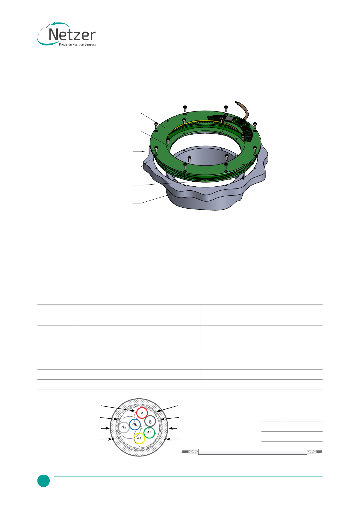
4. Mechanical Drawings
Unless otherwise specied
Dimensions are in: mm Surface nish: N6
Linear tolerances
0.5-4.9: ±0.05 mm 5-30: ±0.1 mm
31-120: ±0.15 mm 121-400: ±0.2 mm
AA BB
Encoder's stator
Encoder's rotor
Customer's shaft
Mounting screws
(not included)
Customer's base
Mounting dowel M2 pins
Customer interface, example, exploded view
90.0
rotor ID
130.0
rotor OD
100.0
stator ID
140.0
stator OD
135.0
stator mounting PCD
95.0
rotor mounting PCD
6 x 2.4
for M2 DIN 912 screws
8 x
2.4
for M2 DIN 912 screws
2.1 X 3.000
2.1 X 3.0
2.1
2.1
The functional zone is
within the ring between
radii 65 and 50 on both
the stator and the rotor
0.1 B
B
2.0
rotor PCB thickness
2.0
stator PCB thickness
1.0 ±0.3
air gap between PCBs
7.0
encoder height include stamp
8.5 ±0.5
encoder height include cable thickness
Avoid presence of any body
made of conductive material
below the rotor's lower surface
within 1 mm under the rotor
and
within the functional zone -
to prevent parasitic capacitance
0.05 0.05
A
0.05
A
Encoder general view
8Product GuideVLP-140-PG-V01
5. Mechanical Interface Control Drawing
AA BB
Encoder's stator
Encoder's rotor
Customer's shaft
Mounting screws
(not included)
Customer's base
Mounting dowel M2 pins
Customer interface, example, exploded view
90.0
rotor ID
130.0
rotor OD
100.0
stator ID
140.0
stator OD
135.0
stator mounting PCD
95.0
rotor mounting PCD
6 x 2.4
for M2 DIN 912 screws
8 x
2.4
for M2 DIN 912 screws
2.1 X 3.000
2.1 X 3.0
2.1
2.1
The functional zone is
within the ring between
radii 65 and 50 on both
the stator and the rotor
0.1 B
B
2.0
rotor PCB thickness
2.0
stator PCB thickness
1.0 ±0.3
air gap between PCBs
7.0
encoder height include stamp
8.5 ±0.5
encoder height include cable thickness
Avoid presence of any body
made of conductive material
below the rotor's lower surface
within 1 mm under the rotor
and
within the functional zone -
to prevent parasitic capacitance
0.05 0.05
A
0.05
A
Encoder general view
Pair# Color
A1-A2 Red / Black
A3-A4 Gray / Blue
A5-A6 Green / Yellow
Cable options
Netzer Cat No. CB 00014 CB 00034
Cable type 30 AWG twisted pair x 3 28 AWG twisted pair x 3
Wire type 2 x 30 AWG 25/44 tinned copper
Insulation: PFE Ø 0.15
OD: Ø 0.6 ± 0.05 mm
2 x 30 AWG 40/44 tinned copper
Insulation: PFE Ø 0.12
OD: Ø 0.64 ± 0.05 mm
Temp. Rating -55°C to +150°C
Braided shield Thinned copper braided 95% min. coverage
Jacket 0.45 silicon rubber (NFA 11-A1) 0.44 silicon rubber (NFA 11-A1)
Diameter Ø 2.45 ± 0.16 mm Ø 3.53 ± 0.16 mm
A1
A2
28 AWG twisted pairs x3
Braid shield
Jacket 0.44 mm
Ø 3.53 ±0.16 mm
30 AWG twisted pairs x3
Braid shield
Jacket 0.45 mm
Ø 2.45 ±0.16 mm
PRODUCT GUIDE
9
Netzer Precision Position Sensors
VLP-140
Hollow Shaft
Kit Encoder
Absolute
Rotary Encoder
VLP-140-PG-V01
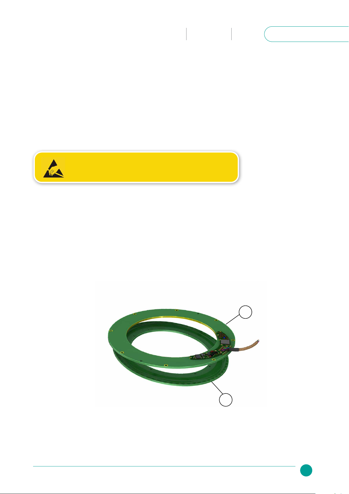
8. Product Overview
8.1 Overview
The VLP-140 absolute position Electric Encoder™ is a rotary position sensor developed for demanding
applications. Currently it performs in a broad range of applications, including defense, homeland security,
medical robotics and industrial automation.
The Electric Encoder™ non-contact technology provides accurate position measurement through the
modulation of an electric field.
The VLP-140 Electric Encoder™ is a kit-encoder, i.e., its rotor and stator are separate.
7. ESD Protection
As usual for electronic circuits, during product handling do not touch electronic circuits, wires, connectors or
sensors without suitable ESD protection. The integrator / operator shall use ESD equipment to avoid the risk
of circuit damage.
6. Storage and Handling
Storage temperature: -55°C to +125°C
Humidity: Up to 98% non-condensing
ATTENTION OBSERVE PRECAUTIONS FOR HANDLING
ELECTROSTATIC SENSITIVE DEVICES
(1) Encoder stator
(2) Encoder rotor
1
2

10 Product GuideVLP-140-PG-V01
8.2 Unpacking - standard order
The package of the standard VLP-140 contains the encoder Stator & Rotor
.
Optional accessories:
(1) CNV-0003, RS-422 to USB converter (with USB internal 5V power supply path).
(2) NanoMIC-KIT-01, RS-422 to USB converter. Setup & Operational modes via SSi /BiSS interface.
(3) RJ VLP-140 rotary jig
(4) DKIT-VLP-140-SG-S0, Mounted SSi encoder on rotary jig, RS-422 to USB converter and cables.
(5) DKIT-VLP-140-IG-S0, Mounted BiSS encoder on rotary jig, RS-422 to USB converter and cables.
8.3 Installation ow chart
Calibration Mounting
correction
YES NO
Mechanical
mounting
Signal
verication
Electric Encoder
Software
installation on PC
Electrical
connection

PRODUCT GUIDE
11
Netzer Precision Position Sensors
VLP-140
Hollow Shaft
Kit Encoder
Absolute
Rotary Encoder
VLP-140-PG-V01
9. Electric Encoder Software Installation
The Electric Encoder Explorer (EEE) software:
●Verifies correct mounting for an adequate signal amplitude
●Calibration of offsets
●General set up and signal analysis
This section describes the steps associated with installing the EEE software application.
9.1 Minimum requirements
●Operating system: MS windows 7/ 10, (32 / 64 bit)
●Memory: 4MB minimum
●Communication ports: USB 2
●Windows .NET Framework, V4 minimum
9.2 Installing the software
●Run the Electric Encoder™ Explorer file found on Netzer website: Encoder Explorer Software Tools
●After the installation you will see Electric Encoder Explorer software icon on the computer desktop.
●Click on the Electric Encoder Explorer software icon to start.
10. Mechanical Mounting
10.1 Encoder mounting - End-of-Shaft Installation
Typical encoder installation uses
●Encoder Stator & Rotor mounting screws Socket Head Cup Screw 12 X M2
●
Encoder Stator & Rotor mounting dowel pins (4), 4 X M2
(not included with the encoder)

12 Product GuideVLP-140-PG-V01
Encoder stator / Rotor relative position
For proper performance the air gap should be 1.0 mm ±0.1 mm
Note: for more information please read section 7
In an optimal mounting, the signal amplitude values generated by the encoder, would be in the middle of the
range of the signal plot shown in the Encoder Explorer software (see plot below). This may vary according to
the encoder type.
Verify proper rotor mounting with the Encoder Explorer tools “Signal analyzer” or “Signal verification process.”
1.0 mm
PRODUCT GUIDE
13
Netzer Precision Position Sensors
VLP-140
Hollow Shaft
Kit Encoder
Absolute
Rotary Encoder
VLP-140-PG-V01
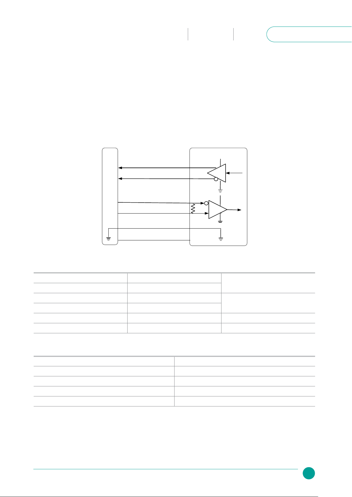
11. Electrical Connection
This chapter reviews the steps required to electrically connect the encoder with digital interface (SSi or BiSS-C).
Connecting the encoder
The encoder has two operational modes:
11.1 Absolute position over SSi or BiSS-C
This is the power-up default mode
5V
Host System
CLK / NCP RX [+]
CLK / NCP RX [-]
5V
5V
120 Ω
(red)
(yellow)
(green)
(blue)
(gray)
(black)
Electric Encoder™
Gnd
DATA / NCP TX [-]
DATA / NCP TX [+]
SSi / BiSS interface wires color code
Clock + Grey Clock
Clock - Blue
Data - Yellow Data
Data + Green
GND Black Ground
+5V Red Power supply
SSi / BiSS output signal parameters
Output code Binary
Serial output Dierential RS-422
Clock Dierential RS-422
Clock frequency 0.1 ÷ 5.0 MHz
Position update rate 35 kHz (Optional - up to 375 kHz)
14 Product GuideVLP-140-PG-V01
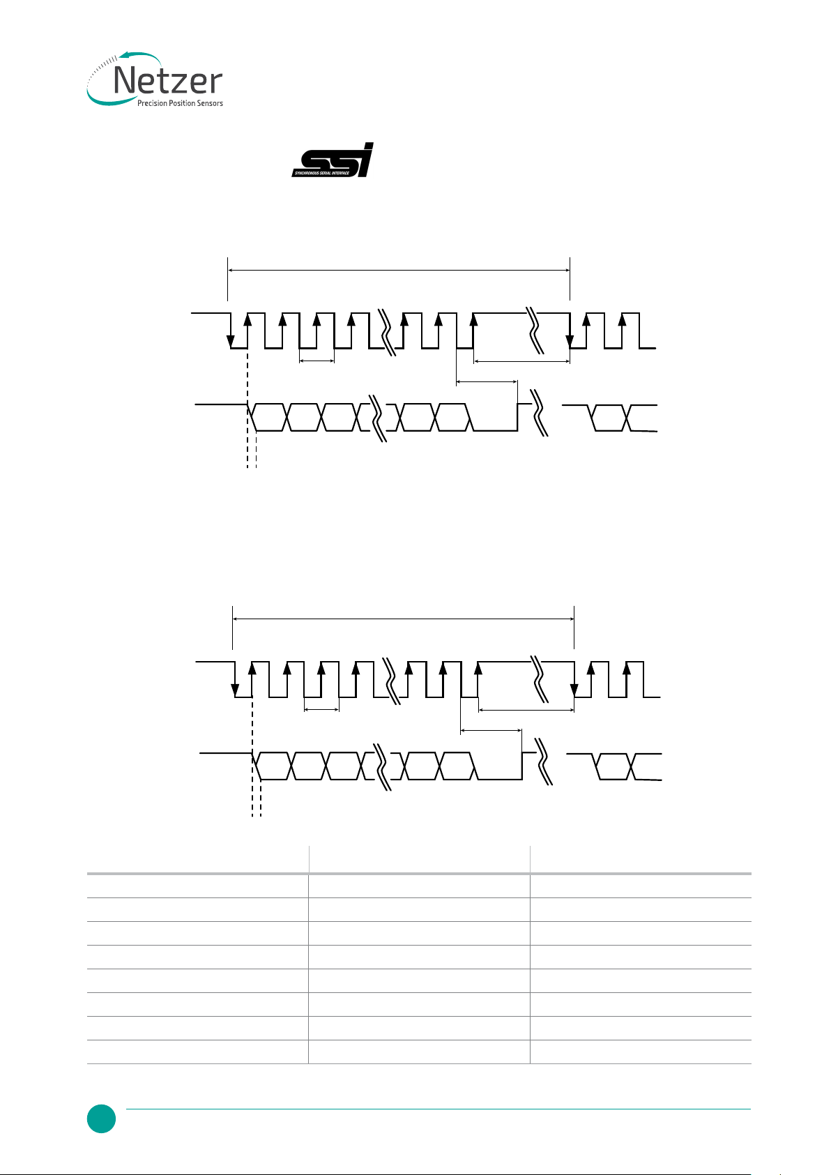
11.2 Digital SSi Interface
Master
Clock
Encoder
Data
Tr
1 2 3 4 n n+1
Tp
T
MSB
Tu
n-1 n-2 n-3 0
LSB
Tm
MSB
Synchronous Serial Interface (SSi) is a point to point serial interface standard between a master (e.g. controller)
and a slave (e.g. sensor) for digital data transmission.
Built In Test option (BIT)
The BIT indicates critical abnormality in the encoder internal signals.
'0' – the internal signals are within the normal limits, '1' – Error
The BIT mechanism, defined in the encoder CAT#, otherwise the Error BIT is always '1'.
Master
Clock
Encoder
Data
Tr
1 2 3 4 n+1 n+2
Tp
T
MSB
Tu
BIT n-1 n-2 0
LSB
Tm
MSB
Description Recommendations
n Position resolution 12-20
T Clock period
f= 1/T Clock frequency 0.1-5.0 MHz
Tu Bit update time 90 nsec
Tp Pause time 26 - ∞ μsec
Tm Monoop time 25 μsec
Tr Time between 2 adjacent requests Tr > n*T+26 μsec
fr=1/Tr Data request frequency

PRODUCT GUIDE
15
Netzer Precision Position Sensors
VLP-140
Hollow Shaft
Kit Encoder
Absolute
Rotary Encoder
VLP-140-PG-V01
BiSS-C Interface is unidirectional serial synchronous protocol for digital data transmission where the Encoder
acts as “slave”transmits data according to “Master”clock. The BiSS protocol is designed in B mode and C mode
(continuous mode). The BiSS-C interface as the SSi is based on RS-422 standards.
Built In Test option (BIT)
The BIT indicates critical abnormality in the encoder internal signals.
'1' – the internal signals are within the normal limits, '0' – Error
The BIT mechanism, defined in the encoder CAT#, otherwise the Error BIT is always '1'.
11.3 Digital BiSS-C Interface
Master
Clock
Position ErrStart TimeoutAck 0 (bits)
Encoder
Data
WCRC (6 bits)
Bit allocation per
encoder-resolution Description Default Length
17bit 18bit 19bit 20bit
27 28 29 30 Ack Period during which the encoder calculates the
absolute position, one clock cycle
0 1/clock
26 27 28 29 Start Encoder signal for “start”data transmit 1 1 bit
25 26 27 28 “0” “Start” bit follower 0 1 bit
8...24 8...25 8...26 8...27 AP Absolute Position encoder data Per
resolution
7777Error BIT (Built In Test option) 1 1 bit
6666Warn. Warning (non active) 1 1 bit
0...5 0...5 0...5 0...5 CRC The CRC polynomial for position, error and warning
data is: x6+ x1+ x0. It is transmitted MSB rst and
inverted.
The start bit and “0” bit are omitted from the
CRC calculation.
6 bits
Timeout
Elapse between the sequential “start”request cycle’s 25 μs
16 Product GuideVLP-140-PG-V01
11.4 Setup mode over NCP (Netzer Communication Protocol)
This service mode provides access via USB to a PC running Netzer Encoder Explorer application (on MS
Windows 7/10). Communication is via Netzer Communication Protocol (NCP) over RS-422 using the same set
of wires.
Use the following pin assignment to connect the encoder to a 9-pin D-type connector to the RS-422/USB
converter CNV-0003 or the NanoMIC.
11.5 Electrical connection and grounding
The encoder does NOT come with specified cable and connector, however, do observe grounding
consideration:
[1] The cable shield does not connect to the power supply return line.
[2] Ground the host shaft to avoid interference from the host system, which could result in encoder internal
noise.
Note: 4.75 to 5.25 VDC power supply required
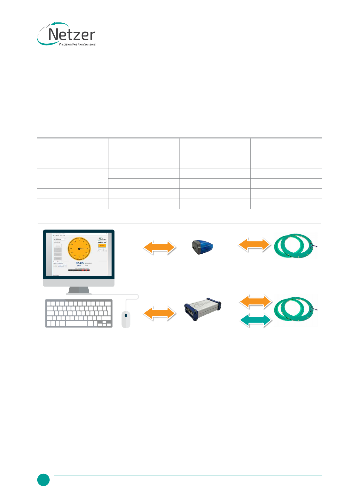
Connect Netzer encoder to the converter, connect the converter to the computer and run the Electric Encoder Explorer
Software Tool
Setup
USB
Setup
USB
SSI / BiSS
Electric
Encoder
NanoMIC
Blue Box Electric
Encoder
or
Electric encoder interface, D Type 9 pin Female
Description Color Function Pin No
SSi Clock / NCP RX Gray Clock / RX + 2
Blue Clock / RX - 1
SSi Data / NCP TX Yellow Data / TX - 4
Green Data / TX + 3
Ground Black GND 5
Power supply Red +5V 8
PRODUCT GUIDE
17
Netzer Precision Position Sensors
VLP-140
Hollow Shaft
Kit Encoder
Absolute
Rotary Encoder
VLP-140-PG-V01
12. Signal Verication
12.1 Starting the Encoder Explorer
Make sure to complete the following tasks successfully:
●Mechanical Mounting
●Electrical Connection to the encoder
●Encoder Explore Software Installation
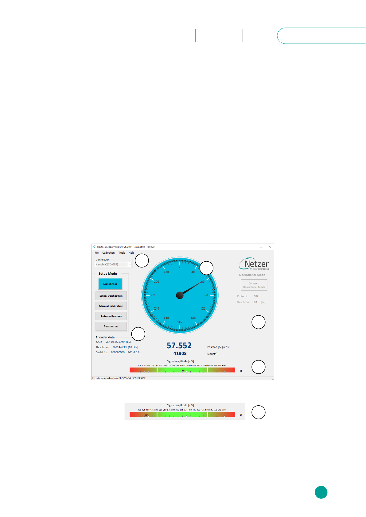
Run the Encoder Explorer tool (EE)
Ensure proper communication with the encoder: (Setup mode by default).
The Encoder position-dial is colored blue when in Setup Mode, either through the NanoMic or the BlueBox (a).
Note that the operational mode is not available through the BlueBox (b).
The Signal amplitude bar indicates whether the signal is within the acceptable tolerance (c) . Note that prior to
performing the Signal Verification process the bar could indicate an out of tolerance signal (d).
Encoder data is displayed in the encoder data area (CAT No., Serial No.) (e).
The position dial display responds to shaft rotation (f).
It is important to perform the Signal Verification process prior to the calibration of the encoder to ensure
optimal performance.
a
b
c
d
f
e
18 Product GuideVLP-140-PG-V01
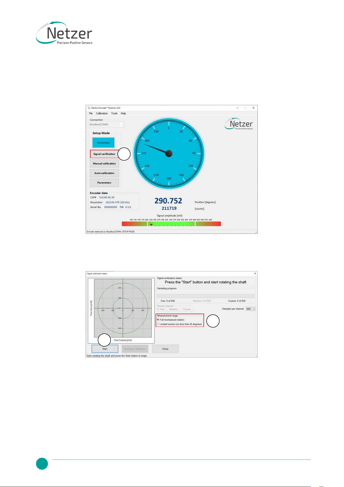
12.2 Signal verication process
The Signal Verification process ensures that the encoder is mounted correctly and provides good signal
amplitudes. This is performed by collecting raw data of the fine and coarse channels during rotation.
●Select <Signal Verification> on the main screen (a).
●Select the appropriate measurement range applicable to your application (b).
●Select <Start> to initiate the process (c).
b
c
a
PRODUCT GUIDE
19
Netzer Precision Position Sensors
VLP-140
Hollow Shaft
Kit Encoder
Absolute
Rotary Encoder
VLP-140-PG-V01
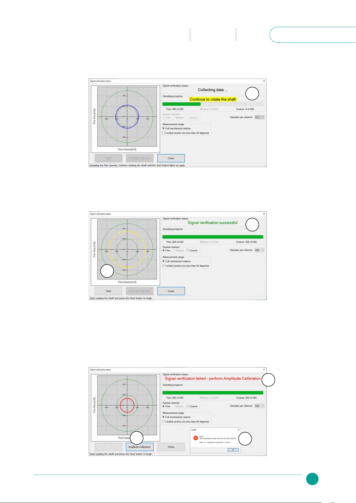
If the process is successful, the status “Signal verification successful” would appear (e).
The ‘amplitude circle’ would be centered between the two green circles, preferably in the middle of the
tolerance (f).
Note however, that mounting the encoder towards the extreme mechanical tolerances might cause the
amplitude circle to be offset from the exact middle of the nominal position.
If the signal is out of tolerance the Error notification“Amplitude is lower/higher than the min/max limit of XXX”
would appear (g).
In Addition, the status “Signal verification failed – perform calibration amplitude” would appear at the top (h).
●Rotate the shaft in order to collect the fine and coarse channels data (d).
d
e
f
ig
h
20 Product GuideVLP-140-PG-V01
Click Ok and Click on the <Amplitude Calibration> button (i).
This process would calibrate the signal amplitudes to ensure an optimal signal, accounting for installation
tolerances.
Follow the series of on-screen prompts:
●Start rotating the shaft and press <OK>
●When the “stop rotation” notification appears, stop the shaft and press <OK>
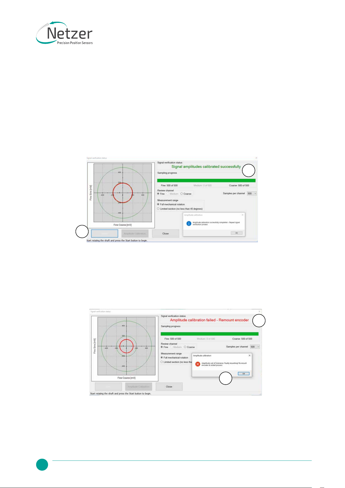
If Amplitude Calibration is successful, the status “Signal amplitudes calibrated successfully” would appear (j).
Close the notification, and repeat the Signal Verification process by clicking the <Start> button (k).
k
j
If the calibration is not possible, the Error notification“Amplitudes out of tolerance. Faulty mounting”appear (l)
and the status “Amplitude calibration failed - Remount encoder” would appear at the top (p).
●Stop the process and re-mount the encoder, making sure that the mechanical installation tolerances are
not exceeded.
p
l
●Repeat the Signal Verification process after the remount.
Once the signal verification process is successfully completed, proceed to the encoder calibration phase,
Section 13
Table of contents
Other Netzer Industrial Equipment manuals

Popular Industrial Equipment manuals by other brands

allen
allen A-71101-EU user manual

Delfin
Delfin LYRA instruction manual

BERGHOF
BERGHOF B-Fortis CC-Prime Series user manual

ITALVIBRAS GIORGIO SILINGARDI
ITALVIBRAS GIORGIO SILINGARDI MVCC Series Technical handbook

PFT
PFT ZP 3 M operating manual

Beko
Beko BEKOSPLIT 14S Instructions for installation and operation


Astronergy
Astronergy Crystalline Silicon PV installation manual

PCB Piezotronics
PCB Piezotronics M261B03 Installation and operating manual

SCHUNK
SCHUNK NSE mini 90 Assembly and operating manual

DANA
DANA SPICER Torque-Hub FBH04 Wet Series Service manual

ADC
ADC HiGain HLU-200 user manual

Agilent Technologies
Agilent Technologies G1531-67000 instructions