4 5
TLM 170 R
The switch does not expand the microphone’s dy-
namic range, b t rather displaces it pward by
10 dB.
The right hand switch alters the –3 dB point of a
b ilt-in high-pass filter.
In the “LIN” position the –3 dB is at 30 Hz and is
intended to protect the microphone inp t from s b-
sonic so nds s ch as air c rrents.
In the other position the –3 dB point is at 100 Hz
which may likewise be sed to s ppress low fre-
q ency interference or to linearize the rise at low
freq encies ca sed by the proximity effect. This is
valid in position “cardioid” for approx. 25 cm dis-
tance, in position “fig re-8” for approx. 50 cm.
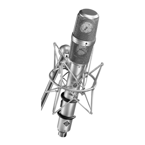
The TLM 170 R is to be mo nted on booms or
stands by means of the swivelable side bracket
whose r bber elements effectively protect the mi-
crophone from mechanically transmitted low-fre-
q ency interference.
This will likely make se of the more complex
EA 170 Elastic S spension accessory nnecessary.
The mike stand thread attached to the side brack-
et has a 5/8"-27 thread as well as a removable
adapter to 1/2" and 3/8" threads.
The microphone cable can be fixed at the side
bracket by clamping it in the slot by means of the
kn rled n t (max. cable diameter 5 mm).
There are other mo nting and s spension methods
which will req ire the removal of this side brack-
et or the bracket may be mo nted to the other side
of the microphone when req ired (see chapter 4).
2.1 Additional Hints for t e Operating of t e
TLM 170 R
The dc-dc converter installed in the microphone
s pplies, in contrast to other circ it conceptions,
also the a dio amplifier and not only the micro-
phone caps le. Since this converter compensates
for variation of the s pply voltage it tries to do
this also when the power s pply is switched off.
Therefore the internal s pply voltage of the micro-
coming from the front b t also for so nd incidence
angles p to ±100°, where the freq ency response
is flat p to 10 kHz. In view of these facts it fol-
lows that the diff se-field response – namely the
response in a lively aco stic environment with re-
flections entering the microphone from all direc-
tions will also be linear. This is of vital impor-
tance in the recording environment and ins res
that the tone color of reverberant so nd will not
be altered by the microphone. This is in sharp con-
trast to an omnidirectional press re transd cer in
which the diff se and direct-field response never
match!
No resonance effects are sed to obtain the char-
acteristics mentioned above. As a conseq ence,
the microphone feat res excellent transient be-
havio r and transmits all transient phenomena of
m sic or voice witho t distortion.
The entire exposed s rface of the caps le, incl d-
ing the membranes, is at gro nd potential making
it imm ne to electric as well as atmospheric con-
ditions and dirt. In order to protect the caps le
from mechanical shock transmission it is elasti-
cally s spended.
A rotary switch at the back permits selection of
five directional patterns: besides the three s al
ones – “omni-directional”, “cardioid”, “fig re-8” –
the intermediate positions “hyper-cardioid” and
“wide-angle-cardioid” are also available. The “hy-
percardioid” is s perior to the “cardioid” for dis-
criminating against so nd to the right and left of
the so rce, whereas the “wide-angle-cardioid” is
preferable for wide so nd so rces s ch as large
instr mental sections or choirs.
The pattern switch is noiseless, with an navoid-
able, short pa se d ring which the microphone is
“dead”.
A sixth switch position of the pattern switch shows
the capital letter RR
RR
R (for Remote Control). In this
switch position, the TLM 170 R directional charac-
teristics can be remote-controlled with the aid of
the N 248 power s pply nit (s. chapter 3.2).
Two additional switches are to be fo nd at the
back of the microphone:
The left one (“–10 dB”) lowers the sensitivity of
the microphone by 10 dB and sho ld only then be
sed when the ens ing amplifier cannot tolerate
the high o tp t level.
stellbaren Richtcharakteristiken besonders ebene
Freq enzgänge, nd zwar nicht n r, wie vielfach
üblich, für den von vorn einfallenden Schall, son-
dern a ch für Schall, der seitlich innerhalb eines
Winkelbereichs von mehr als ±100° einfällt. Da-
her verla fen a ch die Diff sfeld-Freq enzgänge
des TLM 170 R bis 10 kHz parallel z den in Ab-
schnitt 6 gezeigten 0°-Grad-K rven. Praktisch be-
trifft das die indirekt über Reflektionen im A fnah-
mera m z m Mikrophon gelangenden Schallantei-
le. Damit wird a ch ein etwa mita fz nehmender
Nachhallschall d rch das Mikrophon in seinem
Klangcharakter nicht verändert.
Da z m Erreichen der genannten Mikrophoneigen-
schaften keine Resonanzwirk ngen gen tzt wer-
den, ist das Imp lsverhalten des Mikrophons a s-
gezeichnet, nd es vermag alle A sgleichsvorgän-
ge in M sik nd Sprache nverfälscht z übertragen.
Die gesamte Oberfläche der Kapsel einschließlich
der Membranen liegt a f Massepotential nd ist da-
her nempfindlich gegen elektrische nd atmo-
sphärische Einflüsse nd gegen Schm tz. Die Kap-
sel ist z m Sch tz gegen Körperschallübertrag ng
elastisch gelagert.
Mit einem Drehschalter a f der Rückseite können
z sätzlich z den gebrä chlichen drei Richtcharak-
teristiken „K gel“, „Niere“ nd „Acht“ a ch die
Einstell ngen „Hyperniere“ nd „Breite Niere“ ge-
wählt werden. Die „Hyperniere“ gestattet – besser
als die „Niere“ – rechts nd links des a fz neh-
menden Objekts postierte Schallq ellen a sz -
blenden, während die „Breite Niere” vorteilhaft
z r Übertrag ng a sgedehnter Schallq ellen ein-
gesetzt wird.
Die Umschalt ng der Richtcharakteristiken erfolgt
gerä schlos, mit jeweils einer k rzen Umschalt-
pa se, während der das Mikrophon „st mm“ bleibt.
Eine sechste Schalterstell ng des Richtcharak-
teristik mschalters zeigt den Großb chstaben RR
RR
R
(für Remote Control = Fernbedien ng). In dieser
Schalterstell ng können die Richtcharakteristiken
des TLM 170 R mit Hilfe des Netzgerätes N 248
fern mgeschaltet werden (siehe daz Kapitel 3.2).
A f der Rückseite des Mikrophons TLM 170 R be-
finden sich zwei weitere Schalter.
Der linke senkt das Übertrag ngsmaß des Mikro-
phons m 10 dB nd sollte n r verwendet werden,
wenn bei sehr hohen Schalldr ckpegeln für
nachfolgende Geräte die Gefahr der Überste e-
r ng besteht.
Der Schalter erweitert nicht den Dynamik mfang
des Mikrophons, sondern verschiebt ihn m 10 dB
z höheren Schalldr ckpegeln.
Der rechte Schiebeschalter ändert die Grenzfre-
q enz eines im Mikrophon eingeba ten Hochpasses.
In Stell ng „LIN“ ist eine Grenzfreq enz von 30 Hz
eingeschaltet. Dad rch sollen im wesentlichen
dem Mikrophon folgende Geräte vor nterhörfre-
q entem Schall (z.B. starke L ftström ngen) ge-
schützt werden.
In der anderen Schalterstell ng ist eine ntere
Grenzfreq enz von 100 Hz eingeschaltet, wobei
ebenfalls Störq ellen in diesem Freq enzbereich
nterdrückt werden können, oder nter A sn t-
z ng des Naheffektes für in der Nähe postierte
Schallq ellen ein ebener Freq enzgang erhalten
werden kann: In Stell ng „Niere“ bei einem Be-
sprech ngsabstand von ca. 25 cm, in Stell ng
„Acht“ bei ca. 50 cm.
Das TLM 170 R besitzt für die Montage a f einem
Stativ einen seitlich angebrachten schwenkbaren
Bügel, der das Mikrophon d rch eingeba te G m-
mielemente wirksam vor tieffreq enten, mechani-
schen Erschütter ngen schützt.
So wird sich für die meisten Anwend ngsfälle der
Einsatz der noch wirksameren, als Z behör verfüg-
baren Elastischen A fhäng ng EA 170 erübrigen.
Der Stativanschl ss des Bügels besitzt ein 5/8"-
27-Gang Innengewinde mit einem Red zierstück
für 1/2"- nd 3/8"-Gewinde.
Seitlich am Stativanschl ss lässt sich das Mikro-
phonkabel abfangen, indem es mit der Rändelm t-
ter im Schlitz festgeklemmt wird (bis 5 mm Kabel-
d rchmesser).
Der Bügel nd seine Halter ng können vom Mikro-
phon bei Bedarf abgenommen oder a f die ande-
re Seite des Mikrophons montiert werden (siehe
Kapitel 4).
2.1 Einige Zusatzinformationen zum Betrieb
des TLM 170 R
Der im Mikrophon eingeba te dc-dc-Wandler ver-
sorgt im Gegensatz z bisherigen Schalt ngskon-
zepten a ch den NF-Verstärker nd nicht n r die
Mikrophonkapsel. Da dieser Wandler Änder ngen
der Versorg ngsspann ng a sregelt, vers cht er
dies a ch, wenn die Stromversorg ng abgeschal-
tet wird. So bleibt die interne Spann ng des Mi-


