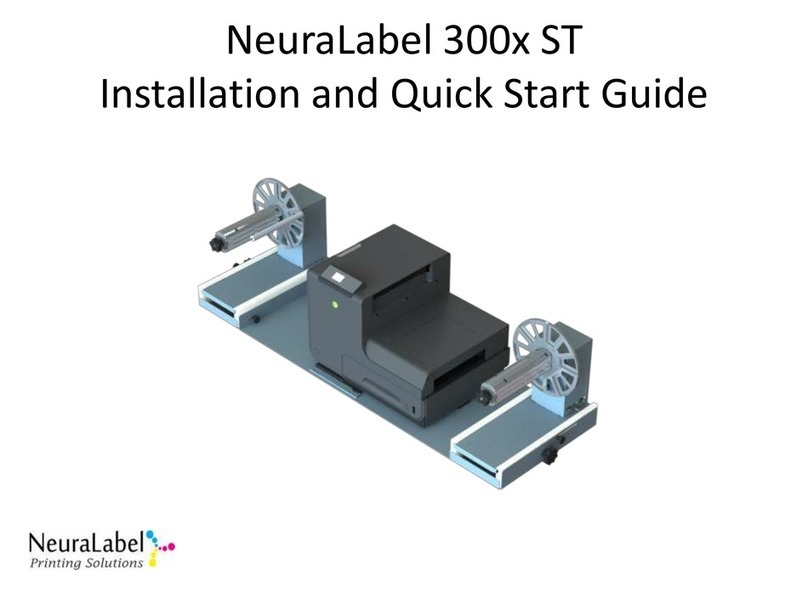
NeuraLabel 300x NoTouch Setup guide

NeuraLabel 300x Toolbox
Quick Start User Guide
Revised 2/2017


NeuraLabel 300x Toolbox Quick Start User Guide
Tools for achieving the best quality prints on the NeuraLabel 300x continuous form printer.
Neuralog LP
Copyright 2017

i

ii
Table of Contents
Introduction to PageWide Technology.....................................................................................................1
Print Quality Reports ...........................................................................................................................2
Built-in PageWide Quality Tools...........................................................................................................3
Toolbox Application and Quality Issues....................................................................................................4
Wide Bands or Die Level ......................................................................................................................5
Narrow Bands or Die Overlap/Alignment.............................................................................................6
Nozzle Out Flush with Print Head Cleaning...........................................................................................7
Image Adjustment ...............................................................................................................................8
Toolbox Preferences and Tools ............................................................................................................9
Using Toolbox for Print Quality Control ................................................................................................. 10
Die Level Adjust for Wide Bands ........................................................................................................ 12
Die Overlap Adjust for Narrow Bands................................................................................................. 16
X and Y Image Adjustment and X Image Stretch................................................................................. 20
Toolbox Preferences.............................................................................................................................. 24
Range Values..................................................................................................................................... 24
Page Setup ........................................................................................................................................ 24
Print Quality Reports ......................................................................................................................... 25
Toolbox Tools ........................................................................................................................................ 27
Perform Auto Calibration................................................................................................................... 27
Clean Print Head (TBD. This option may be removed.) ...................................................................... 27
Diagnostic Reports............................................................................................................................. 27
Debug Window.................................................................................................................................. 28

iii
Table of Figures
Figure 1. NeuraLabel 300x Printhead .......................................................................................................1
Figure 2. NeuraLabel 300x Printhead Spit Pattern ...................................................................................1
Figure 3. NeuraLabel 300x Default Print Quality Report ..........................................................................2
Figure 4. NeuraLabel 300x Custom Print Quality Report.......................................................................... 3
Figure 5. Toolbox Application .................................................................................................................4
Figure 6. Die Level Issue in Magenta Die 7 ...............................................................................................5
Figure 7. Die Alignment in Magenta at Die Seam 5-4 ............................................................................... 6
Figure 8. Nozzle Out in Cyan .................................................................................................................... 7
Figure 9. Original before X Shift ...............................................................................................................8
Figure 10. X Shift Down 1 mm.................................................................................................................. 8
Figure 11. X Shift Down Additional .5 mm................................................................................................8
Figure 12. 300x Toolbox Application .......................................................................................................9
Figure 13. Die Level Adjustment Interface............................................................................................. 12
Figure 14. STEP 1 of Die Level Adjustment ............................................................................................. 13
Figure 15. Printing the Samples ............................................................................................................. 14
Figure 16. Sample print for Die Level Adjustment .................................................................................. 15
Figure 17. Die Overlap Adjustment Interface ......................................................................................... 16
Figure 18. STEP 1 of Die Overlap Adjustment ......................................................................................... 17
Figure 19. Printing the Samples ............................................................................................................. 18
Figure 20. Sample print for Die Overlap/Alignment Adjustment............................................................. 19
Figure 21. Image Shift and Stretch interface .......................................................................................... 20
Figure 22. Web Interface for X Y Image Shift......................................................................................... 22
Figure 23. Image Stretch in Web Server ................................................................................................ 23
Figure 24. Range Preferences ............................................................................................................... 24
Figure 25. Page Setup Panel.................................................................................................................. 25
Figure 26. Print Quality Report Preferences Panel................................................................................. 26
Figure 27. Toolbox Custom Color Selection ........................................................................................... 26

1
Introduction to PageWide Technology
The NeuraLabel 300x printer uses HP PageWide Technology, a breakthrough in inkjet printing that uses
multiple stationary printhead dies, rather than a single moving printhead. While this technology allows
for superior quality and print speeds not possible with prior generation technology, it can also be
problematic because of the individual stationary printhead dies that make up the printhead. The
NeuraLabel 300x toolbox application has been created to address print quality issues related to the
stationary printheads and PageWide Technology.
The printhead for the NeuraLabel 300x printer is shown in Figure 1 below. There are ten printhead dies
with a slight overlap between each pair. These printhead dies are numbered 0 through 9. Figure 2
shows a segment of the “spit pattern” that you will see between print jobs for the ten dies. This spit is
necessary to flush the printhead to ensure maximum quality.
Figure 1. NeuraLabel 300x Printhead
Figure 2. NeuraLabel 300x Printhead Spit Pattern
Die
Overlap
Die

2
Print Quality Reports
The standard Print Quality Report (Figure 3) that can be printed from the printer operator panel shows
the enumeration of the printhead dies. The Print Quality Report shows some, but not all, of the quality
problems that might arise. The 300x Toolbox contains a customizable print quality report that allows
one to easily isolate any quality problems so these issues can be readily addressed. A set of problem-
specific tools is provided to correct each type of quality issue that might arise.
Figure 3. NeuraLabel 300x Default Print Quality Report

3
An example of a custom Print Quality Report is shown below. Notice that each color has the printhead
dies numbered for easier diagnosis. In addition, a custom color has been added.
Figure 4. NeuraLabel 300x Custom Print Quality Report
Built-in PageWide Quality Tools
The NeuraLabel 300x does contain a set of automatic routines that correct many quality issues. These
routines are built in to the three levels of printhead cleaning, accessible through the printer’s operator
panel. The need for Toolbox arose because of specific shortcomings in these automatic routines. These
routines, however are still applicable and often very useful. For any printer with severe quality issues, a
practical approach would be to run the printer’s automatic routines first, and then follow this up with a
fine tuning using the Toolbox application. For specific easily identifiable quality issues, Toolbox can be
immediately used to resolve the quality problem.

4
Toolbox Application and Quality Issues
When the 300x Toolbox Application is launched, a screen like that shown in Figure 5 will appear. The
Printer: list will contain any installed 300x printers available through network or USB. A printer must be
selected from the list before using the application. The Page Setup access the standard Windows
printer driver so that the Quick Print can optionally be formatted to any label size.
There are several areas of quality controls including Wide Bands (Diel Level) Adjustment, Narrow Bands
(Die Overlap) Adjustment, and Image Adjustment.These are selectable by clicking on the large icon
down the left side of the toolbox application; the application interface will update accordingly. Each
control addresses a different category of print quality.
Also notice the Preferences menu that allows configuration of the Quick Print quality report, as well as
the ability to set the Range Values, step size and count, of print samples you will create. The Tools
menu contains a set of specific quality routines for quick access.
Version and product information can be found on the Help->About panel.
Figure 5. Toolbox Application
Select Printer: to get started
Use Page Setup to configure to
your label size
Use Quick Print
Set Preferences->Range Values
to configure samples
Set Preferences->Quick Print to
customize the quality report

5
Wide Bands or Die Level
Uneven wide color bands indicate a need for Die Level Adjustment. These bands will be slightly less
than one inch wide. The examples below shows Die 7 Magenta darker and lighter, respectively. Note
that the die level problem also shows up in the custom color because Magenta is a significant
component of this color.
NOTE: The band example may not be discernable on some computer monitors.
Figure 6. Die Level Issue in Magenta Die 7

6
Narrow Bands or Die Overlap/Alignment
Dark lines that occur at a die seam (indicated on quality report) indicate a need for Die Overlap
Adjustment. These bands will be seen as narrow dark lines in the image. In this case the dies need to be
moved apart.
While thin lines or white shadowy lines that appear at a die seam (indicated on the quality report)
indicate a need for Die Overlap Adjustment. In this case the dies need to be moved closer together.
The examples below show the seam between Die 5 and Die 4 Magenta darker and lighter, respectively.
In the lighter case the dies do not have enough overlap; in the darker case the dies have too much
overlap. Note that the die overlap problem also shows up in the custom color because Magenta is a
significant component of this color.
NOTE: The band example may not be discernable on some computer monitors.
Figure 7. Die Alignment in Magenta at Die Seam 5-4

7
Nozzle Out Flush with Print Head Cleaning
A thin white line that does not appear at a die seam indicates a nozzle out. Nozzle outs are normally
temporary, as the printer automatically compensates for them. However, the Print Head Cleaning
accessed from the printer operator panel can be used to manually correct a nozzle out. The example
below shows nozzle outs in the cyan color. Note that these nozzle outs do not appear in the custom
color because this color contains no significant amount of cyan.
Figure 8. Nozzle Out in Cyan

8
Image Adjustment
Image Adjustment is used to position the image artwork on your diecut media. X Shift moves the
image up or down in the non-continuous direction. The example below shows shifting the image using
the X value to center it on the label. Y Shift would move the image in the continuous direction.
Figure 9. Original before X Shift
Figure 10. X Shift Down 1 mm
Figure 11. X Shift Down Additional .5 mm
Image Stretch is also part of Image Adjustment and can be used to assist full coverage in the continuous
direction. Image Stretch is available as a percentage of length. Usually a very small adjustment to Image
Stretch is all that is required and all that is recommended.

9
Toolbox Preferences and Tools
To use Toolbox to diagnose a quality issue, a Quick Print quality report designed to illustrate print
defects is printed. The report is customized through the Preferences->Quick Print menu and allows you
to print on standard letter size cut sheet or your own custom continuous media. The report includes
Yellow, Cyan, Magenta and Black bars and can include any custom color, allowing you to identify specific
quality issues.
Toolbox also contains a set of Tools for printhead cleaning and diagnostics. A debug log is available as
an advanced feature, useful for technical support to assist in printer diagnostics.
-Select a 300x Printer from the list to use the Toolbox on that printer.
-Configure with Page Setup. Configure to your continuous form custom label size or try cut sheet
from Tray 2.
-Select the Quick Print to print the quality report.
Figure 12. 300x Toolbox Application

10
Using Toolbox for Print Quality Control
Print Quality Issues for the 300x can be separated into the categories just discussed: die color,
alignment between dies, nozzle outs, and the placement of the image on the media. For any bands in
the print, it can be difficult to determine exactly “how dark” or “how light” a band might be. Toolbox
provide a set of steps a user can follow to determine the exact adjustment value needed. These steps
are basically the same for both Wide and Narrow bands. Nozzle outs and Image Placement use a
different approach.
To determine the appropriate adjustment to the printer for Wide or Narrow bands, follow these steps.
They are outlined in the Toolbox application interface. An overview is provided here; more details will
be provided in each corresponding section.
Before you get started: Make sure the printer is selected and configured with Page Setup. Print the
Quick Print to identify a print issue you need to address. For best results, print on your label media.
You will ask:
-Is the problem a wide or narrow band?
-Which die or die seam does the problem occur in?
-Which color(s) does the problem occur in?
For beginner users, address only one issue at a time. Start with Wide Bands before addressing Narrow
Bands. You may be adjusting only one color in a die or multiple colors may need adjusting.
NOTE: If a narrow white line appears that is not at a die seam, it may be a nozzle out. Nozzle outs are
corrected by printhead cleaning, not banding control. Often nozzle outs resolve on their own.
Get Started:
STEP 1: From the Wide Bands or Narrow Bands interface, select the die or die overlap from the grid that
corresponds to the problem shown on the Quick Print. Keep the default value of 0. Advanced
users might use a different start value.
NOTE: It is possible that the Quick Print will be slightly shifted in the printer track and the band
will not exactly align with the numbers printed on the report.
NOTE: If your label is narrower than 8.5 inches, you will only be working with the corresponding
interior dies.
NOTE: It is difficult to detect a lightness or darkness in yellow, unless using a microscope.
STEP 2: Select Make Lighter or Make Darker, depending on the problem. It is possible, but not
recommended to correct multiple bands at the same time. You cannot select to correct both a
lighter and darker band at the same time.
STEP 3: Print a set of samples.
NOTE: The number and step size of samples are set through Preferences->Range Values,
however the defaults for these values should be sufficient.

11
NOTE: The samples and the Quick Print are configured through Preferences->Quick Print. In
this panel you can add a custom color and change the bar size. Adding a custom color from your
label can make isolating a quality issue easier. If your label is small (page size) is small, you may
need to reduce the bar height. If your label is large, using a larger bar height might make seeing
the quality issues easier.
STEP 4: Inspect the samples. Unless you changed the defaults, there will be 5 sets. The first will
represent NO CHANGE, using a value of 0. Find the sample that best corrects the issue and note
the printed correction value. Enter this value in the grid interface at the corresponding
location and click Submit.
STEP 5: Verify the change you just made by selecting Quick Print to view the quality report. If you need
to repeat the samples or slightly adjust the value do so. Note that the value will be overwritten,
not “added to”.
STEP 6: Once you are satisfied with the results, select Save to permanently save the value to the printer.
If at any time you want to completely start over, repower the printer before selecting Save.
The following sections will discuss each of the modes Toolbox includes in more details. Step by step
examples are provided.

12
Die Level Adjust for Wide Bands
Each of the printer’s ten print dies has a “color level” calibration for each of the 4 colors. You may
notice lighter or darker bands of a color in your printed image or in the Print Quality Report. These
bands will be a little less than one inch in width. You will notice a band that is slightly darker or lighter
than its neighbors. These are corrected with the Wide Bands mode for Die Level Adjust.
Select the Wide Bands (Die Level) Mode
Figure 13. Die Level Adjustment Interface
Adjust the level of an individual die/color. At any time you can enter a value in a box in the grid that
corresponds to the die/color you want to alter. This assumes you know the value you want to enter.
Advanced users may acquire this skill.
-Enter value in box.
-Click Submit button to send this value to the printer.
-Click Save button to permanently save this value to the printer.
-Print a Quick Print at any time.
For all other users, follow the 6 step process to address the Wide Band quality issue.

13
Locate the Problem:
-Select your 300x Printer from the list.
-Configure with Page Setup.
-Select the Quick Print.
-Locate the Wide Band on the Quick Print.
Get Started:
STEP 1: Select the box(es) on the grid that correspond to the problem shown on the Quick Print.
Selecting the box will insert a start value of 0 for the samples you will create. Keep the default
value of 0. Advanced users might use a different start value.
NOTE: You may select one or multiple colors for the current die/band.
NOTE: To Unselect any box, delete its value.
NOTE: You can click on the die number at the top to select all colors at once.
Figure 14. STEP 1 of Die Level Adjustment
Click in the grid box. A start value
of 0 is automatically inserted.
Or, click on the number above the
grid for all colors.

14
STEP 2: Select Make Lighter or Make Darker, depending on the problem. It is possible, but not
recommended to correct multiple wide bands at the same time. You cannot select to make
both lighter and darker samples at the same time.
STEP 3: Print a set of samples. Optionally change step size and count through Preferences->Range
Values. Customize the Samples and the Quick Print through Preferences->Quick Print if desired.
Adding a custom color from your label can make isolating a quality issue easier, and adjusting
the Bar Height to fit on your page may be helpful.
Figure 15. Printing the Samples
Other manuals for 300x NoTouch
2
Table of contents
Other NeuraLabel Printer manuals

