b. Invalid measures.
There are two situations where the measure will be declared invalid:
−the pulse signal lasts more than 3 seconds.
•CAUSE: wires are in short circuit with GND, or a prolonged luminous signal beats the photoelectric sensor.
•EFFECT: the count reported is “0” until this condition persists.
−pulse number counted in the time interval exceeds the maximum value of 65,535.
•CAUSE: pulse frequencies very high and sampling intervals very long.
•EFFECT: the reported count is, however, 65,535.
4. Consumption threshold alarms management.
Maximum and minimum consumption threshold alarms may be planned.
The measure is a cumulative value, so the alarm management is performed in differential mode on the threshold interval.
The threshold level is expressed in “last threshold interval counted energy”. This calculation expresses the medium power measured
in the time interval, allowing the identification of moments where the electric consumption increases or decreases related to
expected thresholds.
NOTE: unless the alarm event is notified in the same moment of the sampled measure, it WILL NOT contains measure data. The
energy reported will be ZERO. This situation occurs because of the cumulative measure, the alarm is intended only as a timestamp
where the consumption value changes and not its value.
To obtain the thresholds value, starting by the power, is necessary to consider the time interval of thresholds. Therefore, the Kwh
value must be multiplied with the threshold interval hours number. If the threshold interval is expressed in minutes, the result must
be divided by 60.
Example: 120W maximum threshold setup with threshold interval every 5 minutes
120Wx5/60=10Wh=0.01KWh
➔
the alarm activates if in 5 minutes more than 10Wh are read
5. Device pre-set and use mode.
a. Wireless Mode:
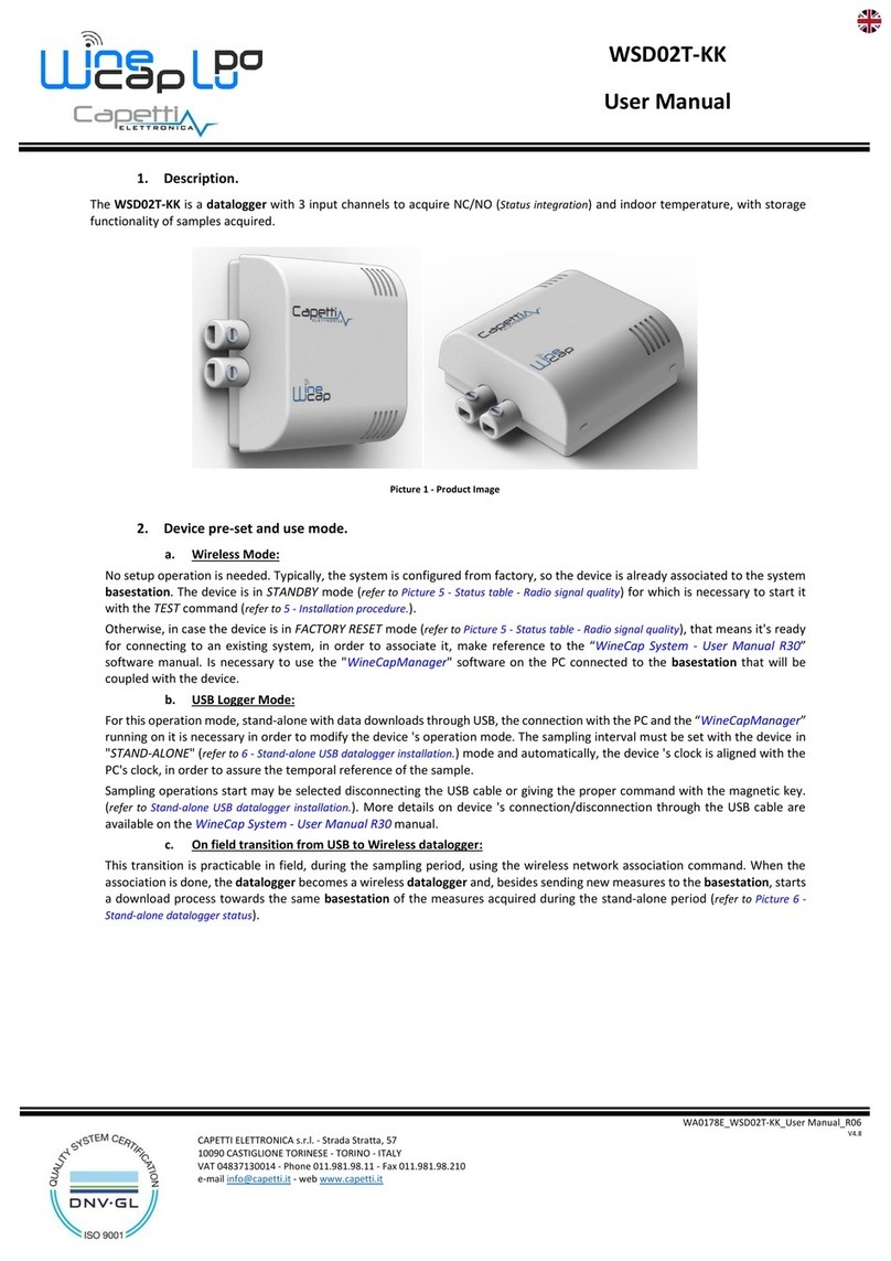
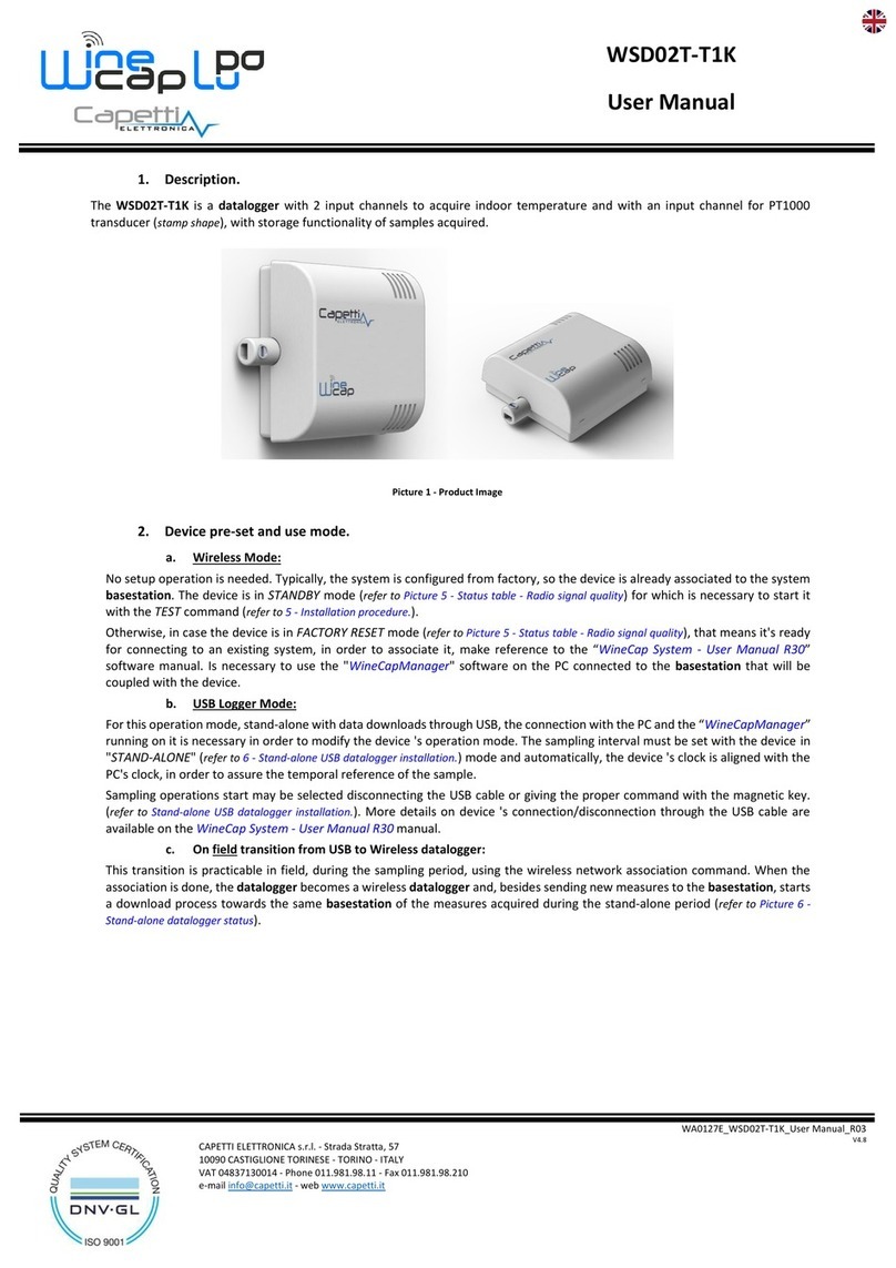
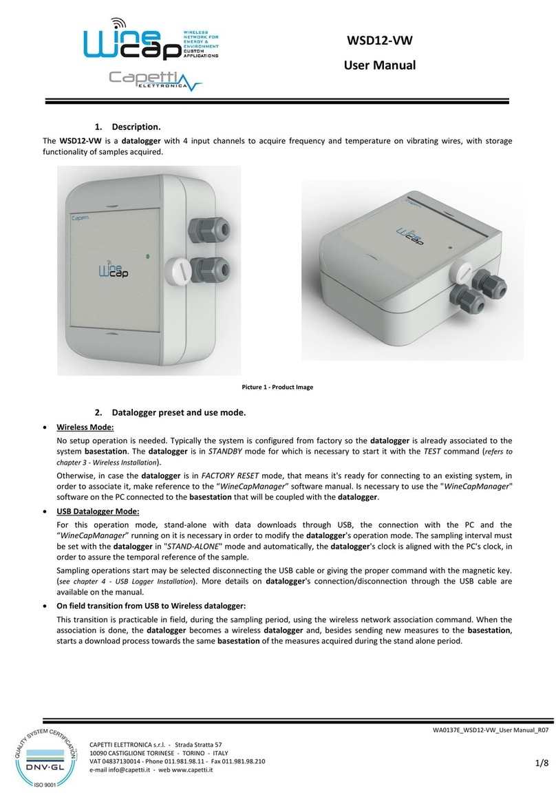
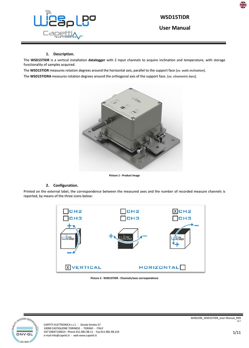
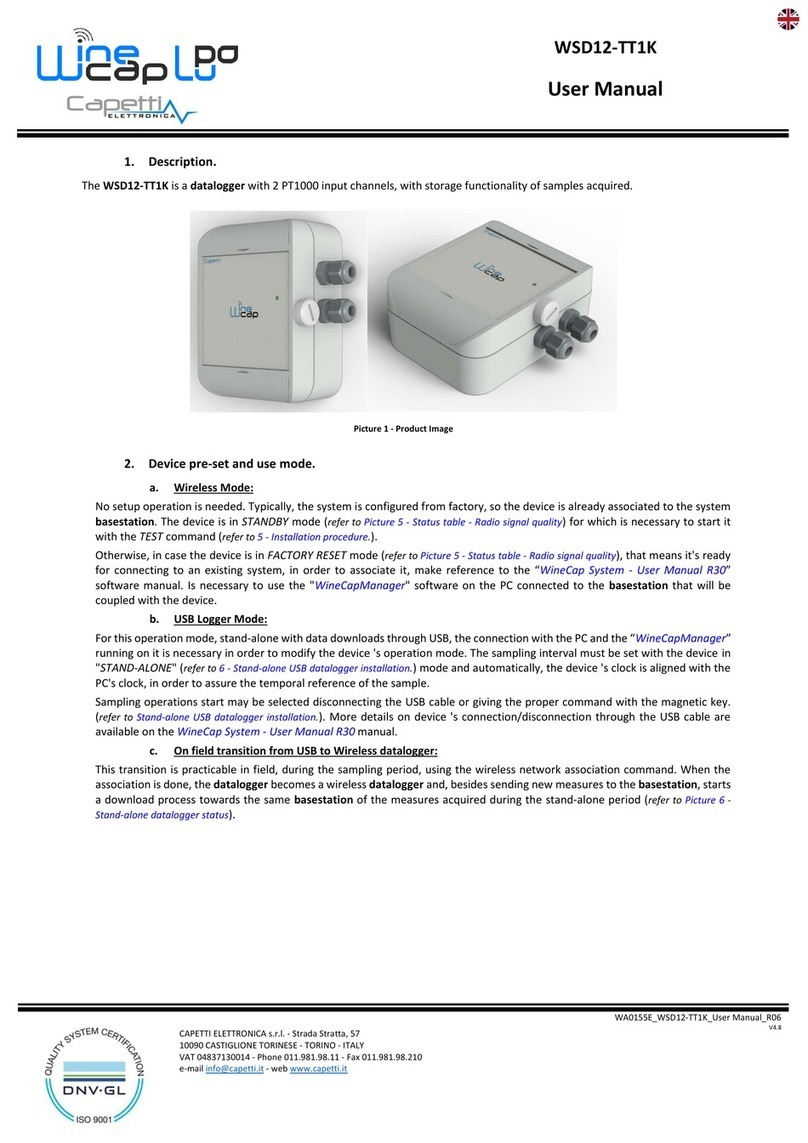
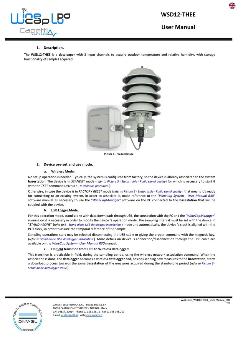
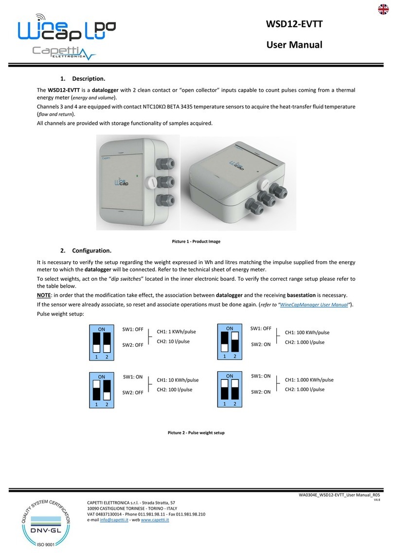
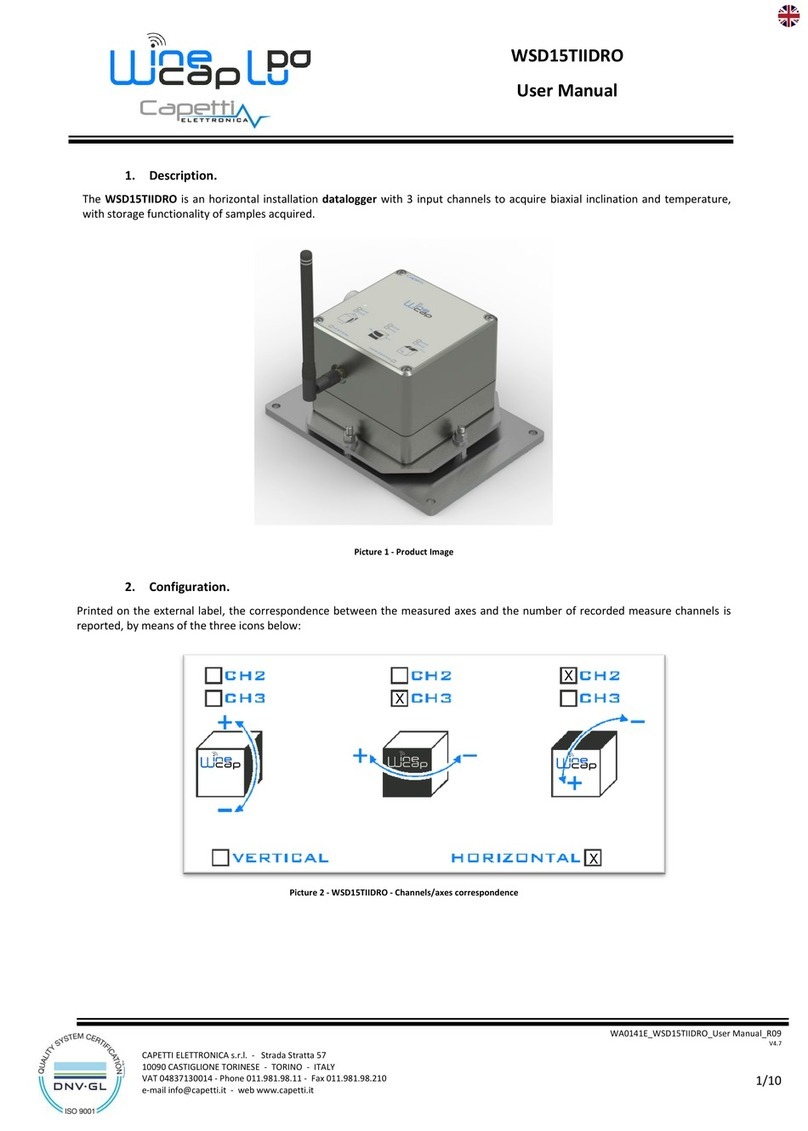
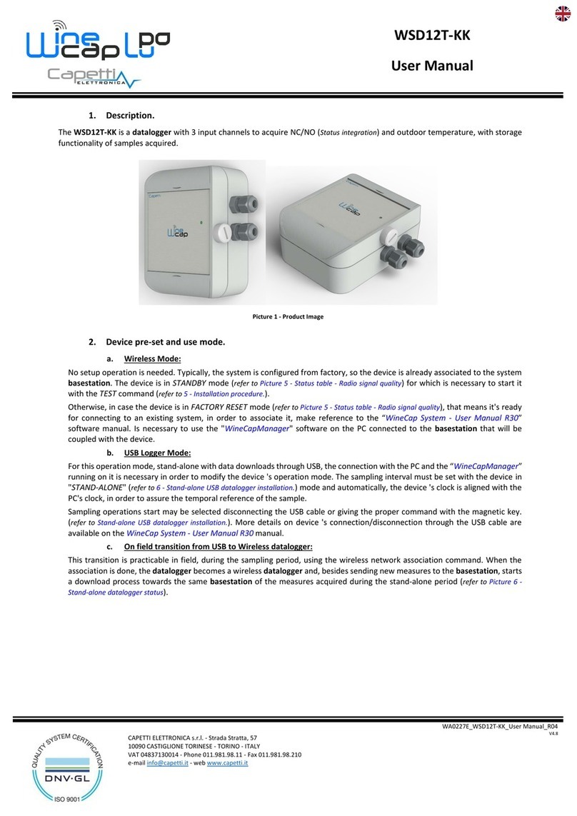
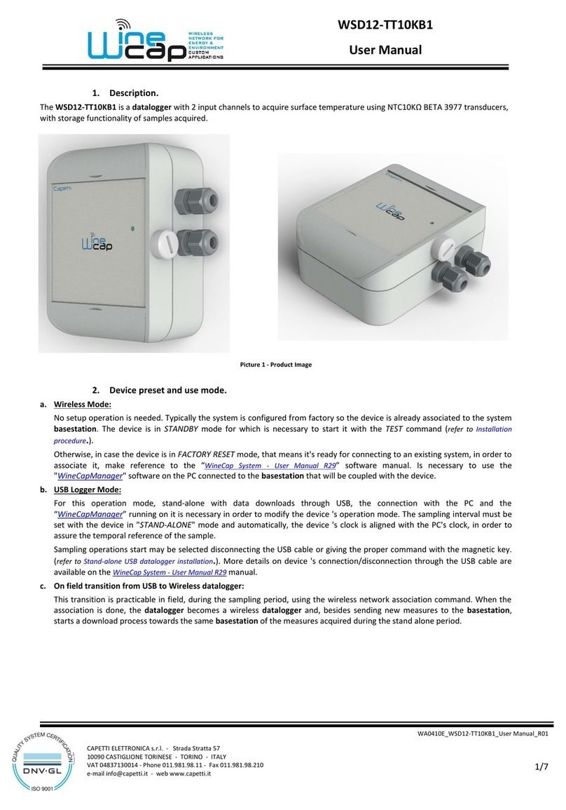
No setup operation is needed. Typically, the system is configured from factory, so the device is already associated to the system
basestation. The device is in STANDBY mode (refer to Picture 7 - Status table - Radio signal quality) for which is necessary to start it
with the TEST command (refer to 8 - Installation procedure.).
Otherwise, in case the device is in FACTORY RESET mode (refer to Picture 7 - Status table - Radio signal quality), that means it's ready
for connecting to an existing system, in order to associate it, make reference to the “WineCap System - User Manual R30”
software manual. Is necessary to use the "WineCapManager" software on the PC connected to the basestation that will be
coupled with the device.
b. USB Logger Mode:
For this operation mode, stand-alone with data downloads through USB, the connection with the PC and the “WineCapManager”
running on it is necessary in order to modify the device 's operation mode. The sampling interval must be set with the device in
"STAND-ALONE" (refer to 9 - Stand-alone USB datalogger installation.) mode and automatically, the device 's clock is aligned with the
PC's clock, in order to assure the temporal reference of the sample.
Sampling operations start may be selected disconnecting the USB cable or giving the proper command with the magnetic key.
(refer to Stand-alone USB datalogger installation.). More details on device 's connection/disconnection through the USB cable are
available on the WineCap System - User Manual R30 manual.
c. On field transition from USB to Wireless datalogger:
This transition is practicable in field, during the sampling period, using the wireless network association command. When the
association is done, the datalogger becomes a wireless datalogger and, besides sending new measures to the basestation, starts
a download process towards the same basestation of the measures acquired during the stand-alone period (refer to Picture 8 -
Stand-alone datalogger status).
