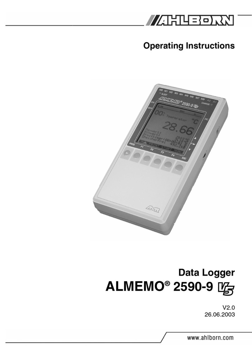
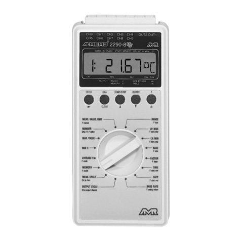
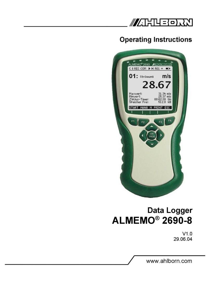
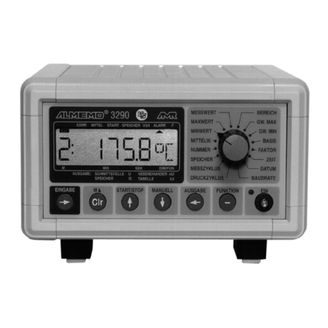
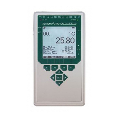
Ahlborn ALMEMO 2690-8A User manual

____________________________
Operating Instructions
Data Logger
ALMEMO® 2690-8A
V4.3
12.10.2012
www.ahlborn.com

1. Operating Controls
1. OPERA ING CON ROLS
(1) Meas. inputs M0 to M4
M0 ... M4 for all ALMEMO-Sensors
M10...M34 15 a itional channels
(2) Output sockets A1, A2
A1 Interfaces USB(ZA1919-DKU)
Interface V24 (ZA 1909-DK5)
Fiber optics V24 (ZA 1909-DKL)
Ethernet (ZA 1945-DK)
RS 422 (ZA 5099-NVL/NVB)
Analog output 2 (ZA 1601-RK)
A2 Network cable (ZA1999-NK5/NKL)
SD car connector (ZA 1904-SD)
Trigger input (ZA 1000-ET/EK)
Relay outputs (ZA 1000-EGK)
Analog output 1 (ZA 1601-RK)
(3) Connector socket DC 12V
Mains a apter(ZA1312-NA8, 12V,1.0A)
USB Cable (ZA1919-DK 5, 5V 0.4A)
DC-Cable isolat. (ZA2690- Kx, 10-30V)
(4) Sleep-LED
(5) LCD display
Status line:
CCont. measuring point scan
© , ll Measurement Start, Stop
REC Memory recor
COM Output of meas. values
l©, ©l Meas. start, en programme
R01 Alarm relay status
* , * Light on, pause
Battery operation/charge status
13 lines for functions
Function of keys F1, F2, F3, F4
(6) Control keys
ON , <POFF> Switch evice on, off
, , Function selection
F1 ... F4 Function keys (soft keys)
PROG Programming
, , Data input
<ESC> Function abort
Last measuring menu
(7) Rubber shock absorber
2 ALMEMO 2690-8
4
5
6
7
123
8
Back of unit:
(8) Battery box
3 Mignon Alkaline Batteries
or 3 Mignon NiCd/NiMH Accumulators
(9) Stand for stand and hang up
(for opening out from 90° to 180°
please press the stan together!)

Table of Contents
2. ABLE OF CON EN S
1. OPERA ING CON ROLS..........................................................................2
3. GENERAL...................................................................................................6
3.1 Guaranteed..........................................................................................6
3.2 Extent of the Delivery .........................................................................6
3.3 Waste disposal....................................................................................7
4. SAFE Y INS RUC IONS..........................................................................8
4.1 Special notes on use...........................................................................9
4.2 Handling batteries / rechargeable batteries correctly......................9
5. IN RODUC ION.........................................................................................9
5.1 Functions...........................................................................................10
5.1.1 Sensor Programming.................................................................10
5.1.2 Measurement.............................................................................12
5.1.3 Process flow control...................................................................13
6. INI IAL OPERA ION................................................................................14
7. POWER SUPPLY.....................................................................................15
7.1 Rechargeable battery operation voltage monitoring......................16
7.2 Battery operating mode....................................................................16
7.3 Mains operation.................................................................................16
7.4 External DC voltage supply..............................................................17
7.5 Sensor Supply...................................................................................17
7.6 Switch On/Off, Reinitialisation.........................................................17
7.7 Data buffering....................................................................................17
8. CONNEC ION OF HE RANSDUCERS................................................18
8.1 ransducers.......................................................................................18
8.2 Measuring inputs and Additional Channels....................................18
8.3 Isolation.............................................................................................19
9. DISPLAY AND KEYPAD..........................................................................21
9.1 Display and Menu Selection.............................................................21
9.2 Function Keys ...................................................................................22
9.3 Control Symbols................................................................................22
9.4 Function Selection............................................................................23
9.5 Data Entry..........................................................................................23
10. MEASURING USING MEASURING-MENUS...........................................24
10.1 Measuring with one Measuring Point............................................25
10.1.1 Selecting the Measuring Point..................................................25
10.1.2 Peak Value Memory with Time an Date..................................25
10.2 Correction of the Meas. Value and Compensation ......................26
10.2.1 Setting the Meas. Value to Zero...............................................26
10.2.2 Zero Point A justment .............................................................27
10.2.3 Sensor A justment in the case of chemical sensors................27
ALMEMO® 2690-8 3

2. Table of Contents
10.2.4 Two-point A justment with Setpoint Entry................................28
10.2.5 Temperature Compensation ....................................................29
10.2.6 Atmospheric Pressure Compensation......................................29
10.2.7 Col Junction Compensation....................................................30
10.3 Measuring point scans and Output...............................................31
10.3.1 Single Output / Storage of all Measuring Points.......................31
10.3.2 Cyclic Output / Storage of all Measuring Points........................31
10.3.3 Memory space, Memory Output, Clearing the Memory............32
10.3.4 Output of Menu Functions........................................................32
10.3.5 Displaying Measure Values as a Line Diagram .....................33
10.4 Averaging.........................................................................................34
10.4.1 Damping of Meas. values by a Sli ing averag. win ow............35
10.4.2 Averaging Mo e.......................................................................35
10.4.3 Averaging over Manual Single Measurements.........................35
10.4.4 Array Measurement..................................................................36
10.4.5 Averaging over the Measuring Time.........................................37
10.4.6 Measurement Time, Measuring uration, Timer.......................37
10.4.7 Averaging over the Cycle..........................................................38
10.4.8 Averaging over several Measuring Points................................39
10.4.9 Volume Flow Measurement......................................................40
10.5 Display of Several Measuring Points ............................................41
10.5.1 Menu Multi Channel Display an Bar chart...............................41
10.5.2 Differential Measurement.........................................................41
10.5.3 Menu List of Measuring Points.................................................42
10.6 Assistant-Menus for Special Meas. Operations............................43
10.6.1 Thermal Coefficient..................................................................43
10.6.2 Wet Bulb Globe Temperature...................................................43
10.7 User Menus......................................................................................44
10.7.1 Functions..................................................................................44
10.7.2 Configuration of the menus .....................................................45
10.7.3 Function Printouts....................................................................46
11. PROGRAMMING WI H PROGRAMMING-MENUS.................................47
11.1 imes and Cycles............................................................................47
11.1.1 Time an Date .........................................................................47
11.1.2 Cycle with Storage Activation an Output Format....................47
11.1.3 Conversion Rate, Continuous Measuring Point Scan...............48
11.1.4 Time an Date of Start, Time an Date of En ........................49
11.2 Data Memory....................................................................................50
11.2.1 Memory connector with SD car ...............................................50
11.2.2 Data Acquisition.......................................................................51
11.2.3 Numbering of measurements...................................................52
11.2.4 Starting an Stopping of measurements..................................52
11.2.5 Scanning mo e........................................................................52
11.2.6 Memory Output.........................................................................54
4 ALMEMO 2690-8

Table of Contents
11.3 Sensor Programming......................................................................55
11.3.1 Selecting the Input Channel......................................................55
11.3.2 Measuring Point Designation....................................................56
11.3.3 Averaging Mo e.......................................................................56
11.3.4 Locking the Programming of the Sensor..................................56
11.3.5 Limit Values..............................................................................57
11.3.6 Scaling, Decimal Point Setting..................................................57
11.3.7 Correction Values.....................................................................58
11.3.8 Changing the Dimension..........................................................58
11.3.9 Selecting the Measuring Range................................................58
11.3.10 Function Channels .................................................................61
11.3.11 Special meas. ranges, linearization, calibration......................62
11.4 Special Functions............................................................................63
11.4.1 Print Cycle Factor.....................................................................63
11.4.2 Minimum Sensor Supply Voltage..............................................63
11.4.3 Limit Value Responses.............................................................64
11.4.4 Analog Output Start an En ....................................................65
11.4.5 Output Function........................................................................65
11.4.6 Reference Channel 1................................................................66
11.4.7 Reference Channel 2 or Multiplexer.........................................66
11.4.8 Element Flags..........................................................................66
11.5 Device Configuration......................................................................67
11.5.1 Device Designation...................................................................67
11.5.2 Device A ress an Networking...............................................67
11.5.3 Bau Rate, Data Format...........................................................68
11.5.4 Language.................................................................................68
11.5.5 Lighting an Contrast...............................................................68
11.5.6 Atmospheric Pressure..............................................................68
11.5.7 Hysteresis.................................................................................69
11.5.8 Operating Parameters..............................................................69
11.6 Output Modules...............................................................................69
11.6.1 Data cable................................................................................70
11.6.2 Relais Trigger mo ules............................................................70
11.6.3 Analog Output..........................................................................72
11.7 Menu Power Supply........................................................................73
11.8 he locking and calibration menu (option KL).............................74
12. ROUBLESHOO ING..............................................................................75
13. DECLARA ION OF CONFORMI Y.........................................................76
14. APPENDIX................................................................................................77
14.1 echnical Data ................................................................................77
14.2 Product overview ...........................................................................78
14.3 Keyword index.................................................................................79
14.4 Your contact....................................................................................83
ALMEMO® 2690-8 5

3. General
3. GENERAL
Congratulations for buying this innovative ALMEMO® ata logger. By means of
the patente ALMEMO® connectors the evice configures itself an with the
help of menus an help win ows the operation shoul not be too ifficult. How-
ever, the evice allows the connection of a great variety of sensors an peri-
pherals with many special functions. For getting to know the function range of
the sensors an the iverse possibilities of the evice, you really shoul rea
these operating instructions an the correspon ing chapters of the ALMEMO®
manual. This is the only way to avoi operating an measuring errors as well
as amages of the evice. For a quick answer to all questions, a etaile
keywor in ex is provi e at the en of the instructions an of the manual.
3.1 Guaranteed
Every evice has to pass through several quality tests before leaving the
works. For a perfect function, a guarantee of two years from the elivery ate
is grante . Before sen ing back the evice, please pay attention to the in ica-
tions in chapter 12. Troubleshooting. Shoul there actually be a efect, please
use the original packing material for epatch if possible an enclose an ex-
pressive escription of the trouble in connection with the correspon ing circum-
stances.
In the following cases a guarantee benefit is exclu e :
After forbi en operations an changes in the evice by the client
Operating in surroun ing con itions that are not vali for this pro uct
Using unsuitable power supply an peripherals
Using the evice in a way it is not etermine for
Damages through electrostatic ischarge or flash of lightning
Not paying attention to the operating instructions
Changes in the pro uct features in favour of technical progress or ue to new
components are reserve to the pro ucer.
3.2 Extent of the Delivery
While unwrapping the elivery, pay attention to amages of the evice an to
its completeness:
Measuring instrument ALMEMO® 2690-8A with 3 AA NiMH
(nickel-metal hy ri e) rechargeable batteries
Rubber shock absorber with a stan ,
these operating instructions,
ALMEMO® Manual,
CD with Software AMR-Control an useful accessories
In case of a transportation amage, the packing material is to be kept an the
supplier is to be informe imme iately.
6 ALMEMO 2690-8

Waste isposal
3.3 Waste disposal
The pictogram showing a waste bin crosse through
means that the pro uct is subject to European Union regu-
lations on segregate waste isposal. This applies both to
the pro uct itself an to any accessories marke with the
same symbol. Disposal of any such item as unsorte o-
mestic waste is strictly forbi en
•Please ispose of all packaging materials accor ing to the applicable national
waste management regulations.
•Please ispose of car boar boxes, protective plastic packaging materials,
an all preservative substances separately an in the proper manner.
•The isposal of the evice itself (also of evice parts, accessories, an con-
sumables) is subject to the applicable national an local waste management
regulations an to the environmental protection legislation in force in the
country of use.
•Please ispose of all waste in the proper manner;
this applies in particular to all parts an substances that constitute a hazar
for the environment. This inclu es inter alia plastics, batteries, an re-
chargeable battery packs .
•When isposing of goo s, please wherever possible use the original pack-
aging materials.
ALMEMO® 2690-8 7

4. Safety instructions
4. SAFE Y INS RUC IONS
DANGER Danger to life and limb, risk of damage to equipment
Read the instructions carefully before starting to operate
the device.
Please ensure that you comply with all general safety ad-
vice and the special safety instructions included in other
chapters.
Such risks may occur in the following circumstances :
•Failure to hee the operating instructions an all the
safety notes these contain
•Any form of unauthorize tampering or alteration in-
si e the evice
•Use of the evice in environments or con itions for
which it is not suite
•Use of the evice with an unsuitable power supply
an / or in conjunction with unsuitable peripheral
equipment
•Use of the evice for any purpose other than that for
which it is inten e
•Damage cause by electrostatic ischarge or light-
ning.
DANGER Risk of fatal injury caused by dangerously high voltage
Such risks may occur in the following circumstances :
•Use of the evice with an unsuitable power supply an
/ or in conjunction with unsuitable peripheral equip-
ment
•Damage cause by electrostatic ischarge or lightning
•Do not run sensor lines in the vicinity of high-voltage
power cables.
•Before you touch any sensor lines, ensure that all stat-
ic electricity has been ischarge .
DANGER Warning - explosive atmospheres or substances
In the vicinity of various fuels or chemicals there is a risk of ex-
plosion.
Do not use the evice in the close vicinity of blasting work or
filling stations!
8 ALMEMO 2690-8

Special notes on use
4.1 Special notes on use
•If the evice is brought into the work-room from a col environment
there is a risk that con ensation might form on the electronics. In
measuring operations involving thermocouples pronounce changes in
temperature may cause substantial measuring errors. You are a -
vise therefore to wait until the evice has a juste to the ambient
temperature before starting to use it.
•Before using the mains a apter make sure that the mains voltage is
suitable.
•Be sure to observe the maximum loa capacity of the sensor power
supply.
•Sensors with their own integrate power supply are not electrically isol-
ate from one another
4.2 Handling batteries / rechargeable batteries correctly
When inserting batteries / rechargeable batteries ensure that
these are correctly polarize .
If the evice will probably not be nee e for a relatively long
perio of time or if the batteries are empty, remove the batteries;
this will prevent battery aci leaking onto the evice an am-
aging it.
Rechargeable batteries shoul be recharge as an when ne-
cessary.
You shoul never attempt to recharge an or inary (non-re-
chargeable) battery; it may explo e !
Batteries / rechargeable batteries must never be short-circuite
or thrown onto the fire.
Batteries / rechargeable batteries are special waste an must
not be iscar e together with normal omestic waste.
5. IN RODUC ION
The ata logger ALMEMO® 2690-8 is a new instrument from the unique
pro uct range of measuring evices that are all equippe with the ALMEMO®
connector system, which has been patente by Ahlborn GmbH. The intelligent
ALMEMO® connector provi es important a vantages with regar to the con-
nection of sensors an peripherals as all parameters are store in an EEP-
ROM within the connector. As a result, the programming that usually has to be
performe for the connection is not require . All sensors an output mo ules
ALMEMO® 2690-8 9

5. Intro uction
can be connecte to all ALMEMO® measuring evices in the same way. The
operation an programming is i entical with all units. Therefore, all of the AL-
MEMO® measuring system items liste below are escribe , in etail, in a sep-
arate ALMEMO® manual that is supplie with every evice:
Detaile escription of the ALMEMO® system (manual section 1)
Overview of the evice functions an measuring ranges (manual section 2)
All sensors with basic principles, operation, technical ata (man. section 3)
The options for connecting existing sensors (manual section 4)
All analog an igital output mo ules (manual section 5.1)
The interface mo ule RS232, fiber optics, Centronics (manual section 5.2)
The entire ALMEMO® networking system (manual section 5.3)
All functions an their control via the interface (manual section 6)
A complete interface comman list with all print outputs (manual section 7)
These operating instructions only cover features an controls that are specific
for a certain evice. As a result, many sections will often provi e a note refer-
ring to the more etaile escription within the manual (man. sect. x.x.x).
5.1 Functions
New ata logger ALMEMO® 2690-8A now comes fitte with an 1024-KB EEP-
ROM sufficient for some 200,000 measure values, a low-power A/D convert-
er, an integrate charge circuitry for recharging the batteries. The measuring
possibilities are virtually unlimite ; there are 5 electrically isolate measuring
inputs suitable for all ALMEMO® sensors, or 20 channels in the sensor con-
nectors an 4 evice-internal function channels - with over 70 measuring
ranges. For operation purposes the evice incorporates an LCD graphics is-
play an a softkey keypa with cursor block. The isplay can be a apte by
means of configurable user menus to suit any application. Two output sockets
allow for connecting any ALMEMO® output mo ules, for example, the igital in-
terface, memory car , analogue output, trigger input or alarm contacts. Several
evices can be networke by simply connecting them with network cables.
5.1.1 Sensor Programming
The measuring channels are automatically programme by the ALMEMO®
connectors. However, the user can easily complete or mo ify the programming
via keyboar or via interface.
Measuring Ranges
There are correspon ing measuring ranges for sensors with a non-linear char-
acteristic such as 10 thermocouple types, Ntc an Pt100 sensors, infrare
sensors, an flow sensors (rotating vanes, thermoanemometers, pitot tubes).
Humi ity sensors are available with function channels that also calculate hu-
mi ity ata such as ew point, mixture ratio, vapour pressure an enthalpy.
Even complex chemical sensors can be use . The acquisition of measure
10 ALMEMO 2690-8

Functions
ata from other sensors is easily possible by using the voltage, current an
resistance ranges with in ivi ual scaling in the connector. Existing sensors can
be use without problems. Only the correspon ing ALMEMO® connector has
to be connecte using its terminals. Furthermore, there are a apter connectors
with an own microcontroller for igital signals an for measuring frequencies
an pulses. This way, nearly all sensors can be connecte to any ALMEMO®
measuring instrument an are interchangeable without requiring any settings.
Function Channels
Maximum, minimum, average values an ifferences of certain measuring
junctions can be programme as function channels, also in evice internal
channels, an can be processe an printe like normal measuring junctions.
Furthermore, function channels for special measuring tasks are provi e to e-
termine the temperature coefficient Q/∆T an wet bulb globe temperature.
Dimension
The 2 igit imension can be altere for each measuring channel so that the
isplay an the printout will always in icate the correct imension, for example
when a transmitter is connecte . The conversion from °C to °F is automatically
performe accor ing to the imension.
Name of Measured Values
For i entification of the sensors a 10- igit alphanumeric name is provi e . It is
entere via the keypa or the interface an appears on the isplay, the printout
or the computer isplay.
Correction of Measured Values
For correcting measure values a zero point an slope correction can be ap-
plie to the measure value of each measuring channel. This also allows for
sensors to be interchange that usually, at first, require an a justment (expan-
sion, force, pH). The zero point an the slope correction are virtually performe
by the push of a button.
Scaling
The base value an the factor allow for a further scaling of the correcte meas-
ure value of each measuring channel for zero point an slope. The ecimal
point position can be set by the exponent. By setting to zero an entering the
nominal value the scaling values can be automatically calculate .
Limit Values and Alarm
Two limit values (1 max an 1 min) can be set for each meas. channel. If a lim-
it value is excee e alarm contacts, that can be in ivi ually allocate to limit
values, are provi e by means of relay output mo ules. As a stan ar , the
hysteresis is set to 10 igits; however, it can also be a juste between 0 an
99 igits. Furthermore, limit value excee ing can also be use to start or stop a
ata logging.
ALMEMO® 2690-8 11

5. Intro uction
Sensor Locking
All sensor ata store in the EEPROM of the connector can be protecte
against un esire access by means of a gra e locking function.
5.1.2 Measurement
A total of up to 20 meas. channels are available for 5 trans ucers, i.e. it is also
possible to evaluate ouble sensors, in ivi ually scale sensors, or sensors
with function channels. The meas. channels can be successively selecte for-
war s or backwar s via keypa . By efault all measuring points are scanne
continuously at a measuring rate of 10 mops an the ata thus obtaine is lis-
te on the isplay. However, if you want to have the measure values for the
selecte channel sent to an analog output, it may be an a vantage to use
semi-continuous mo e instea ; the output value will then always be refreshe
at half the measuring rate set - irrespective of the number of measuring points
involve .
Measured Values
The measure values of 1 to 20 measuring points can be in icate on the is-
play in ifferent menus (that can also be configure ) in three font sizes, as bar
graph or as line chart. They are automatically acquire with auto zero an self
calibration an can also be arbitrarily correcte an scale as require . A
sensor breakage con ition is, with most sensors, automatically etecte .
Analog Output and Scaling
By means of analog start an analog en any measuring point can be scale
so that the resulting measuring range covers the full range of the bar graph or
line chart or of an analog output (2V, 10V or 20mA). The measure value of
any measuring point as well as a programme value can be output to the ana-
log output
Measuring Functions
Special measuring functions are require for some sensors to achieve an op-
timal ata acquisition. The col junction compensation is available for thermo-
couples, a temperature compensation for ynamic pressure an pH an
con uctivity probes, an an atmospheric air pressure compensation for humi -
ity sensors, ynamic pressure sensors an O2 sensors. With infrare sensors
the parameters zero point an slope correction are use for backgroun tem-
perature an emissivity factor.
Max and Min Value
Each measurement involves an acquisition an storage of the Max value an
the Min value inclu ing the time an ate. The values can be isplaye , printe
or cleare .
Average Value
Measure values can be expresse as a sli ing average obtaine by continu-
ous automatic smoothing or average over a particular perio or cycle or over
a series of in ivi ual measuring operations.
12 ALMEMO 2690-8

Functions
5.1.3 Process flow control
A continuous measuring point scan with a time-base process flow control for
the output of measuring valures is require to register the measuring ata of all
connecte sensors. For this purpose, an output cycle is available an , if fast
processing is require , the conversation rate is available. The measurement
can be starte an stoppe by using the keyboar , the interface, an external
trigger signal, the real time clock or an excee ing of limit values.
ime and Date
The real time clock with ata function or the pure measuring time are use for
an accurate recor ing of any measurement. Start an en time/ ate can be
programme in or er to start or stop a measurement.
Cycle
The Cycle is programmable between 1 s an 59 h, 59 min an 59 s an
provi es a cyclic output of measure values to the interfaces or memories an
also provi es a cyclic averaging.
Print Cycle Factor
If necessary, the print cycle factor allows for limiting the ata output of particu-
lar channels so that an excessice ata flow can be limite , especially uring
ata storage.
Average Value over Measuring Point Scans
The measure values resulting from scanning measuring junctions can be av-
erage as esire either over the total measuring time or over the cycle time.
Function channels are available for a cyclic output an storage of these aver-
age values.
Conversion Rate
With the ALMEMO® 2690-8A all measuring points can be continuously
scanne with the conversion rate (2.5;10 50 or 100 M/s). To realize a high re-
cor ing spee it is possible to store all measure values in the memory an /or
to perform an output via the interface.
Data Memory
During the cycle, all measure values can be manually or automatically store
in an EEPROM. The memory capacity is, as stan ar , 1024 Kilobyte, which al-
lows up to 200.000 measure values. The memory organisation can be con-
figure as linear or ring memory.The output can be carrie out via the isplay
or the interface. It is possible to specify a selection accor ing to a time interval
or number.
Numbering of Measurements
By entering a number, single scans or entire series of measurements can be
i entifie an selectively rea out from the memory.
Control Outputs
Via keyboar an interface allows to in ivi ually trigger up to 4 output relays
ALMEMO® 2690-8 13

5. Intro uction
an one analog output.
Operation
All measuring an function values can be isplaye in ifferent menus on the
ot matrix LCD isplay. 3 user menus can be in ivi ually configure from
nearly 50 functions for your specific applications. Using texts, lines an blank
lines allows to format the printout in an application-specific style. Nine keys
(four of them are soft keys) can be use to operate the evice. This also allows
you to fully program the sensors, the evice an the process control.
Output
All ata logs, menu functions an store measure values an programme
parameters can be provi e as output to any peripheral equipment. Various in-
terface cables can be use to provi e a RS232, RS422, Centronics or Ethernet
interface. The output of measuring ata can be selecte in list format, columns
or sprea sheet format. Files in sprea sheet format can be processe by each
sprea sheet software. The print hea er can be programme specifically to the
company or application.
Networking
All ALMEMO® evices can be a resse an can be easily networke by
simply linking them using network cables, or RS422 network istributors for
longer istances.
Software
The AMR-Control software, which allows for the entire programming of the
sensors, the configuration of the measuring instrument, of the user menus an
the rea -out of the ata memory is supplie with each ALMEMO®manual. The
integrate terminal also allows for online measurements. The WINDOWS®
software WIN-Control is available for ata acquisition of networke evices,
graphical presentation an complex ata processing.
6. INI IAL OPERA ION
Sensor connection Connect trans ucers to the sockets M0 to M4 (1), s. 8.
Power supply with batteries/accumulators or mains adapter on DC (3) s. 7.1, 7.3
Switch-on Press key ON / PROG (6), s. 7.6
Automatical isplay of the last measuring menu, s. 10. keys:
Menu selection MEAS.-Menus: call up with key: < ESC > or F4
e.g. select menu StandardDisplay , s. 9.1 / ... ( F )
Call up the menu with key:
Select meas. point (s. 10.1.1) with keys: / ... ( M )
Select function Max/MinVal (s. 9.4) with: PROG , ...
Clear max/min values, s. 10.1.2 < CLR > or F1
14 ALMEMO 2690-8

Initial Operation
Output of measuring data or memory via interface:
- Connect peripheral evice, via ata cable, to socket A1 (2), s. man. 5.2
- Set 9600b , 8 ata bits, 1 stop bit, no parity at peripheral evice
Single output/storage, s. 10.3.1 < MAN > or F2
Cyclic measurement: Select Cy le-Timer : PROG , ...
Enter cycle (hh:mm:ss) s. 9.5 Cy le-Timer: 00:05:00Sn
Output format list ´ ´, columns ´n´, table ´t´ < FORM> or F3 ...
Stop programming < ESC> or F4
Start/stop the cyclic measurement, s. 10.3.2 <START> , <STOP> or F1
Output of memory data to printer or computer:
Select the function Memory Free with: PROG , ...
Memory ata output, s. 11.2.6 < PRINT> or F3
Clear memory, s. 11.2.6 < CMEM >
7. POWER SUPPLY
Power can be supplie to the instrument in any of the following ways :
3 AA NiMH batteries with integrate charge circuitry (supplie as stan ar ).
3 AA alkaline batteries
Mains a apter 12 V, 1.0 A, with ALMEMO® connector ZA 1312-NA8
Electrically isolate power supply cable (10 to 30 VDC, 1 A) ZA 2690-UK2
USB ata supply cable (5 V, 0.4 A) ZA 1919-DKU5
Our pro uct line inclu es correspon ing accessories.
ALMEMO® 2690-8 15
F1 F2 | F3 F4
ON PROG
F1 F2 | F3 F4
ON PROG
* ALMEMO 2690-8 *
±±±±±±±±±±±±±±±±±±±±±±±±±±±±±±±±±±±±
MEASURING-Menus:
Standard display ©
U1 Meas. value orre tion
U2 Averaging
U3 Volume flow
Data logger
Multi hannel display
*List of measuring points
Bar harts
Line diagram
_____________________
Menu1 PROGRAMMING-Menus
Menu2 ASSISTANT-Menus
POFF *ON F MENU1 MENU2
C © REC COM l© ©l R01 * ´´´´´´µµµµ
¯¯¯¯¯¯¯¯¯¯¯¯¯¯¯¯¯¯¯¯¯
01: Velo ity m/s
æ » H º
28.67
Maximum value: 31.34 mls
Minimum value: 25.37 mls
Cy le-timer: 00:02:30 Un
Memory free: 512.0 kB
START MANU M PRINT ESC

7. Power supply
7.1 Rechargeable battery operation voltage monitoring
Power is supplie to the measuring instrument as stan ar by 3 NiMH batter-
ies. At a current consumption of approx. 17 mA the operating time will be ap-
prox. 110 hours. If the isplay illumination is left switche on, this operating
time will be re uce to approx. 20 to 50 hours ( epen ing on brightness). To
prolong the operating time for the purposes of long-term recor ing the evice
can be left in SLEEP mo e. (see 11.2.5) The operating voltage can be
checke in the power supply menu; this gives you a basis for estimating the
remaining operating time. (see 11.7)
As soon as the remaining battery capacity rops to approx. 10%, the battery
symbol ´´µµµµµµµµµ¶ in the status bar of the isplay will start to flash. As an when
this happens you shoul connect mains a apter ZB 1112-NA7 (12 V / 1 A) an
recharge the batteries; this will take aroun 3 hours; further elay may result in
critically low ischarge an this may amage the batteries. (see 7.3)
The NiMH rechargeable batteries can in fact be recharge at any time an in
any charge status using the intelligent charge circuitry. The charging current
an charge status can be checke an monitore at any time in the power
supply menu. If the batteries are completely ischarge , the evice will switch
off but measure ata an the time-of- ay will be save . (see 7.7)
Rechargeable batteries have specially co e bare contacts (serial numbers up
to 1110...) so that the evice will charge these only - an not normal batteries.
7.2 Battery operating mode
Instea of the rechargeable batteries you can use 3 AA alkaline batteries.
Those have higher capacity permitting operation over 160 hours. In or er to re-
place the batteries, the sensors must be isconnecte an remove , the rubber
protection (7) must be pulle off, an the battery cover (8) on the rear of the
evice must be unscrewe an lifte off in the irection in icate by the arrow.
7.3 Mains operation
To power the evice from an external source preferably use the mains a apter
ZA 1312-NA7 (12 V / 1.0 A); connect this to the DC socket (3). The sensor
voltage is set automatically to 12 volts. If rechargeable batteries are being
use , these will then be charge . (see 11.7)
16 ALMEMO 2690-8

External DC voltage supply
7.4 External DC voltage supply
It is also possible, at DC socket (3), to connect a USB ata supply cable (5 V,
0.4 A) ZA1919-DKU5 or, via ALMEMO® connector (ZA1000-FSV), to connect
any other DC voltage (6 to 12 V, minimum 200 mA). If, however, the power
supply has to be electrically isolate from the trans ucers or if a larger input
voltage range (10 to 30 V) is require , then electrically isolate supply cable
ZA2690-UK (250 mA) or -UK2 (1 A) must be use . It will then be possible to
use the measuring instrument in a 12-volt or 24-volt on-boar supply system.
7.5 Sensor Supply
At the terminals + (plus) an - (minus) in the ALMEMO® connector there is a
configurable sensor supply voltage available (self-healing fuse, 500 mA). The
sensor voltage supplie by the evice is set automatically, epen ing on the
minimum supply voltage requirements of the sensors, to 6 V (200 mA), 9 V
(150 mA), or 12 V (100 mA). (s. 11.4.2) (see also the power supply menu
11.7) Other voltages (12, 15, or 24 volts or references for a potentiometer an
strain gauge) can also be obtaine using special connectors. (see Manual.
Sections 4.2.5 an 4.2.6) .
7.6 Switch On/Off, Reinitialisation
To switch on the evice press the key ON PROGr (6) in the mi le of the cursor
block. There always appears the last calle up meas. menu first in the isplay.
To switch off the evice leave a working menu with <ESC>r an press the
softkey <P-OFF>r in the menu selection. After switch-off the real time clock con-
tinues its operation an all store ata remains available (s. 7.7).
If the evice shows an irregular behaviour ue to interference influences (e.g.
electrostatic charging or battery failure), the evice can be reinitialise . The re-
set can be achieve if the key F1 r is presse uring switch-on. If the complete
evice programming with times, terms of evice, user menus etc. is to be set
to the elivery efaults, the key F4 r must be presse uring switch-on. Only
the sensor programming within the ALMEMO® connectors will not be attache
by this reset.
The reset function on power are not possible when the AC a apter is
plugge in an the batteries are charge !
7.7 Data buffering
The sensor programming is store in the EEPROM of the sensor connector,
the calibration an the programme parameter of the evice is fail-safe store
in the EEPROM of the evice. Time an ate are buffere by a lithium battery
so that storage of the ata is also guarantee without batteries an when the
evice is switche off.
ALMEMO® 2690-8 17

8. Connection of the Trans ucers
8. CONNEC ION OF HE RANSDUCERS
Any ALMEMO® sensors can be connecte to the ALMEMO® input sockets M0
to M4 of the measuring instrument (1). For connecting existing sensors it is
only necessary to connect a correspon ing ALMEMO® connector.
8.1 ransducers
A etaile escription of the comprehensive ALMEMO® sensor range (see
manual section 3) an the connection of existing sensors (see manual section
4) to the ALMEMO® instruments are provi e in the ALMEMO® manual. All
stan ar sensors with ALMEMO® connector usually have the measuring range
an imension alrea y programme an can be imme iately connecte to any
input socket. A mechanical co ing ensures that sensor an output mo ules
can only be connecte to the correct sockets. Furthermore, each ALMEMO®
connector has two locking levers that snap in when the insertion into the socket
is establishe an that prevent a isconnection cause by pulling the cable.
Both levers must be presse on the si es for isconnecting the connector.
Especially for the evice ALMEMO® 2690-8, new sensors with rea y-ma e AL-
MEMO® connectors are available. They offer a splash-proof enclosure for the
sockets ue to their ouble sealing lips. For unuse sockets there are ummy
connectors.
8.2 Measuring inputs and Additional Channels
The measuring instrument ALMEMO 2690-8 has 5 input sockets (1) that the
measuring channels M0 to M4 are initially allocate to. However, ALMEMO®
sensors can, if require , provi e up to 4 channels so that 20 channels are
available with 5 input sockets. The a itional channels can be especially use
with humi ity sensors with 4 measuring variables (temperature/humi ity/ ew
point/mixture ratio) or use for function channels. If require , the sensor can
also be programme with several ranges or scaling or, epen ing on the pin
assignment, 2 or 3 sensors can be combine in one connector (e.g. rH/Ntc,
mV/V, mA/V etc.). The a itional measuring channels of a connector are in-
crease in steps of 10 (e.g. the first sensor has the channels M0, M10, M20,
M30, the secon sensor has the channels M1, M11, M21, M31 etc.).
Device-internal channels:
An innovation on this evice is its four extra a itional channels. The first of
these M5 is programme by efault as ifferential channel M1 – M0. This only
happens, however, if there are two sensors with the same units an same
ecimal point position connecte at measuring points M0 an M1. However, all
four channels can be programme with any other function channels (e.g. U-
Bat, CJ, average, volume flow, etc.); (s. 11.3.10, man. 6.3.4). Mb1 = M1 an
Mb2 = M0 are always use as reference channels by efault.
18 ALMEMO 2690-8
Measuring inputs an A itional Channels
Advantage of the evice-internal channels: If several sensors are being use
for the same application, they o not have to be reprogramme an can be
freely exchange without losing their function channels. If, however, the whole
application operates with just one sensor, then programming in the sensor it-
self makes more sense.
On the measuring instrument this gives the following channel assignment:
8.3 Isolation
When buil ing up a working measuring arrangement, it is very important that
there cannot flow any compensation currents between sensors, power supply
an peripherals. This is the case when all measuring points are on the same
potential or when unequal potentials are electrically isolate .
The 5 analog inputs are electrically isolate by photovoltaic relais an between
them a potential ifference of at most 50 V DC or 60V AC is permitte . How-
ever, combine sensors within one connector an sensors with power supply
are elelctrically connecte ; therefore they must be operate isolate ly. The
voltage at the measuring inputs (between B,C,D an A or -) must not excee
12V!
The power supply is isolate by the transformer of the mains a apter or by the
DC/DC-converter in the a apter cable ZA2690-UKx. Data an trigger cables
are equippe with optocouplers. At electrically not isolate cables of the analog
ALMEMO® 2690-8 19
M0 M1 M2 M3 M4
00
10
20
30
03
13
23
33
04
14
24
34
01
11
21
31
02
12
22
32
1. Channel
A2 A1 DC
05
15
25
35
Device-internal channels
Difference M01-M00
Sensor channels
2. Channel
3. Channel
4. Channel
M2
M1
M0
Data cable
AC
DC
DC
DC
ADC uC
U-
U+
Sensors
Power supply
10..30V=

8. Connection of the Trans ucers
output, the registration evice or the sensors have to be potential free.
Electrically isolated A/D converter (option G )
With option OA2690-GT the analog inputs ownstream from the A/D converter
are also electrically isolate from the evice itself an from the power supply by
means of optocouplers. In environments subject to particularly heavy isturb-
ance this will usually improve measuring quality; it will also be possible to sup-
ply the evice on a non electrically isolate basis - e.g. via a USB ata supply
cable (ZA1919-DKU5) or a simple ALMEMO supply connector (ZA1000-FSV).
It will also be possible, via a non electrically isolate analog output cable, to
perform measuring operations at points with potentials up to 50 V.
However, some components are not electrically isolate , namely all sensors
connecte to the common internal power supply ±U. For these sensors elec-
trical isolation has to be isable ; in some cases this will even require a switch
S (see above) or wire jumper; some inputs woul otherwise be left without ref -
erence potential. (see 11.4.8 Configuration with element flag 5 'ISO OFF' is
usually set automatically the first time the evice is connecte .) With certain
connectors (especially ivi er connectors without power supply) element flag 5
shoul be checke an if necessary correcte .
20 ALMEMO 2690-8
M2
M1
M0
Data cable
AC
DC
DC
DC
ADC uC
U-
U+
Sensors
Power supply
10..30V=
230V≈
electr. isol. S
DC DC
A
B
Other manuals for ALMEMO 2690-8A
1
Table of contents
Other Ahlborn Data Logger manuals

Ahlborn
Ahlborn ALMEMO 500 User manual

Ahlborn
Ahlborn ALMEMO 470 User manual

Ahlborn
Ahlborn ALMEMO 500 User manual

Ahlborn
Ahlborn ALMEMO 2590-9 V5 User manual

Ahlborn
Ahlborn ALMEMO 3290-8 V5 User manual

Ahlborn
Ahlborn ALMEMO 2690-8A User manual

Ahlborn
Ahlborn ALMEMO 500 User manual

Ahlborn
Ahlborn ALMEMO 2290-8 User manual

Ahlborn
Ahlborn ALMEMO 2890-9 User manual

Ahlborn
Ahlborn Almemo 8990-8 User manual