NeurOptics PLR-4000 User manual
PLR®-4000 Pupillometer
Instructions For Use

NeurOptics® PLR®-4000 Pupillometer System—Instructions for Use ©2023 NeurOptics, Inc.
Introduction
Table of Contents
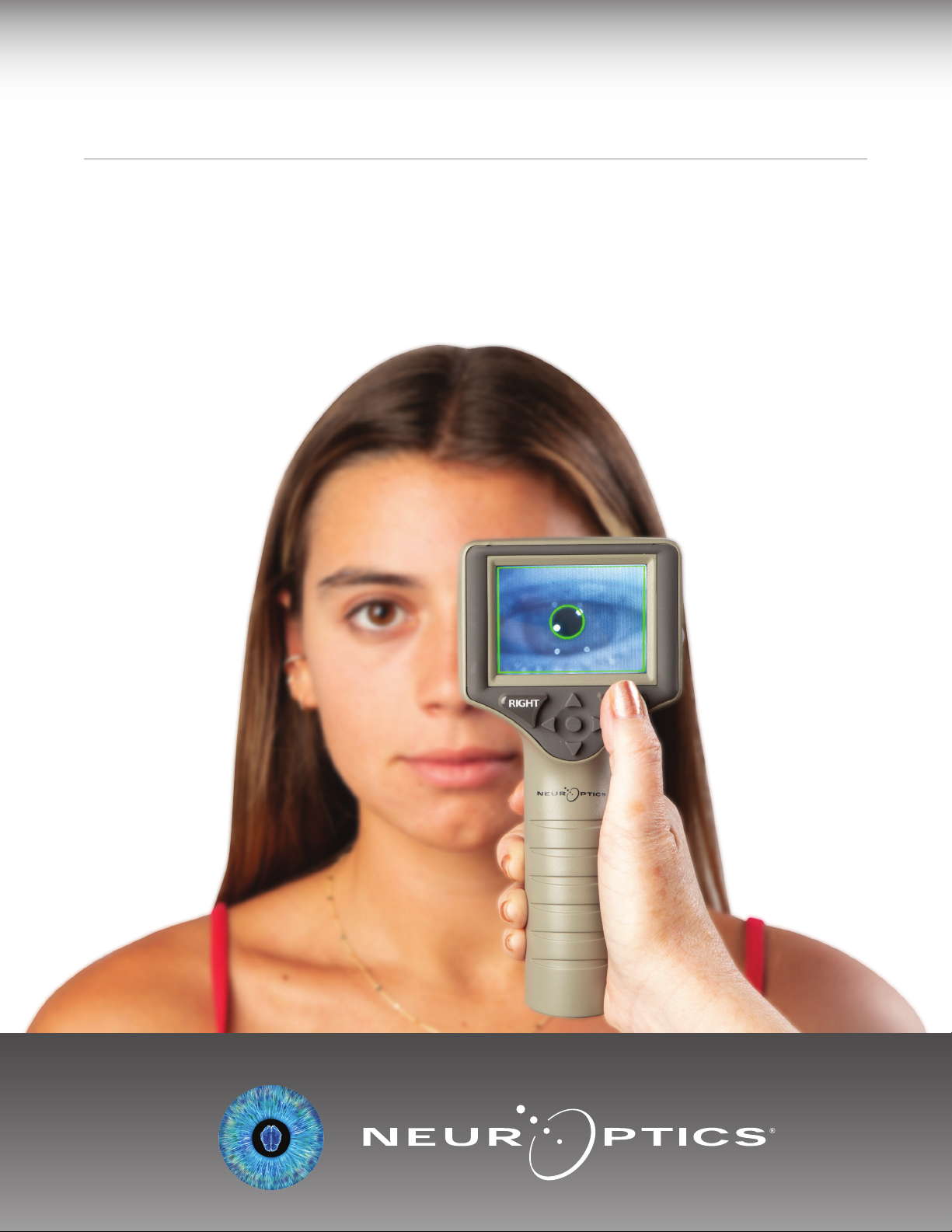
The NeurOptics® PLR®-4000 Pupillometer oers clinicians quantitative infrared technology to objectively and
accurately measure pupil size and dynamics in an advanced design. The PLR-4000 provides a comfortable
ergonomic design, incorporated barcode scanner, wireless charging, and easy-to-read touchscreen LCD and
graphics.
Indications for Use
The PLR-4000 Pupillometer is a handheld optical scanner which measures pupil size and pupil reactivity. The
results obtained from the PLR-4000 scans are used for information only and are not to be used for clinical
diagnostic purposes. The PLR-4000 should only be operated by properly trained clinical personnel, under the
direction of a qualified physician.
Contraindications
Avoid use when the orbit structure is damaged, or surrounding soft tissue is edematous or has an open lesion.
Warnings and Cautions .......................................3
Classification .....................................................3
Patents, Copyright and Trademark Notice ... .. .. .. .. .. 3
Safety Information .............................................3
Getting Started .................................................4
Power Up .........................................................4
Measuring Pupils ................................................5
Set Measurement Protocol ..................................6
Video Replay .....................................................8
Browse Records ...............................................9
Download Data .................................................9
Print Data .........................................................9
PupilMeasurements–SpecialConsiderations.........10
PLR-4000 PupillometerNavigationGuide.............10
Troubleshooting ...............................................11
Power O .........................................................11
Handling, Cleaning and Maintenance ..................12
CustomerService..............................................12
OrderingInformation.........................................13
Appendix A
Pupillary Measurement Parameters ......................13
Appendix B
Technical Specifications...................................13
Appendix C
International Symbol Definition ....................... 14
Appendix D
Wireless Printing Range and Frequency ............15
2

NeurOptics® PLR®-4000 Pupillometer System—Instructions for Use ©2023 NeurOptics, Inc.
Warnings and Cautions
Warnings
Warnings and Cautions appear throughout this manual
where they are relevant. The Warnings and Cautions listed
here apply generally any time you operate the device.
•The PLR-4000 is intended for use by trained clinical
personnel, under the direction of a qualified physician.
•If a problem is recognized while operating the device,
the device must be removed from use and referred to
qualified personnel for servicing. Do not use the device
if damage to the housing or internal optical components
is apparent. Using an inoperative device may result in
inaccurate readings.
•Electric shock hazard – Do not open the device or the
charging station. There are no user serviceable parts.
•The battery in the PLR-4000 is only replaceable by
a qualified NeurOptics’ service technician. Contact
NeurOptics if you suspect an inoperable battery.
•Use only the NeurOptics Charging Station for charging
the PLR-4000.
•Risk of fire or chemical burn – This device and its
components may present a risk of fire or chemical burn
if mistreated. Do not disassemble, expose to heat above
100°C, incinerate, or dispose of in fire.
•Store and use the PLR-4000 System in ambient
environments with non-condensing humidity levels
only. Using the PLR-4000 with condensation on optical
surfaces may result in inaccurate readings.
Cautions
The following cautions apply when cleaning the device.
•The internal components of the PLR-4000 are NOT
compatible with sterilization techniques, such as ETO,
Steam Sterilization, Heat Sterilization and Gamma.
•DO NOT submerge the device or pour cleaning liquids
over or into the device.
•DO NOT use acetone to clean any surface of the
PLR-4000 or Charging Station.
Electromechanical Compatibility (EMC) Notice
This device generates, uses, and can radiate radio
frequency energy. If not set up and used in accordance
with the instructions in this manual, electromagnetic
interference may result. The equipment has been tested
and found to comply with the limits set forth in EN60601-
1-2 for Medical Products. These limits provide reasonable
protection against electromagnetic interference when
operated in the intended use environments (e.g. hospitals,
research laboratories).
Magnetic Resonance Imaging (MRI) Notice
This device contains components whose operation can be
aected by intense electromagnetic fields. Do not operate
the device in an MRI environment or in the vicinity of high-
frequency surgical diathermy equipment, defibrillators,
or short-wave therapy equipment. Electromagnetic
interference could disrupt the operation of the device.
Federal Communications Commission Compliance
This device complies with Part 15 of the Federal
Communications Commission (FCC) Rules. Operation is
subject to the following two conditions: (1) this device may
not cause harmful interference, and (2) this device must
accept any interference received, including interference
which may cause undesired operation.
Classication
Type of Equipment: Medical Equipment, Class 1 886.1700
Trade Name: NeurOptics® PLR®-4000 Pupillometer
Manufactured by:
NeurOptics, Inc.
9223 Research Drive
Irvine, CA 92618, USA
p: + 1-949.250.9792
Toll-Free North America: 866.99.PUPIL
info@NeurOptics.com
NeurOptics.com
Patents, Copyright and Trademark Notice
Copyright ©2023 NeurOptics, California.
This work is protected under Title 17 of the U.S. Code and
is the sole property of NeurOptics, Inc. (the Company).
No part of this document may be copied or otherwise
reproduced, or stored in any electronic information
retrieval system, except as specifically permitted under
U.S. Copyright law, without the prior written consent of
the Company.
For details, visit: www.NeurOptics.com/patents/
Safety Information
•Please review the following safety information prior to
operating the device.
•Please read these Instructions fully before attempting
to use the PLR-4000. Attempting to operate the device
without fully understanding its features and functions
may result in unsafe operating conditions and/or
inaccurate results.
•If you have a question regarding the installation,
set-up, operation, or maintenance of the device, please
contact NeurOptics.
3
NeurOptics® PLR®-4000 Pupillometer System—Instructions for Use ©2023 NeurOptics, Inc.
4
Getting Started
Power Up
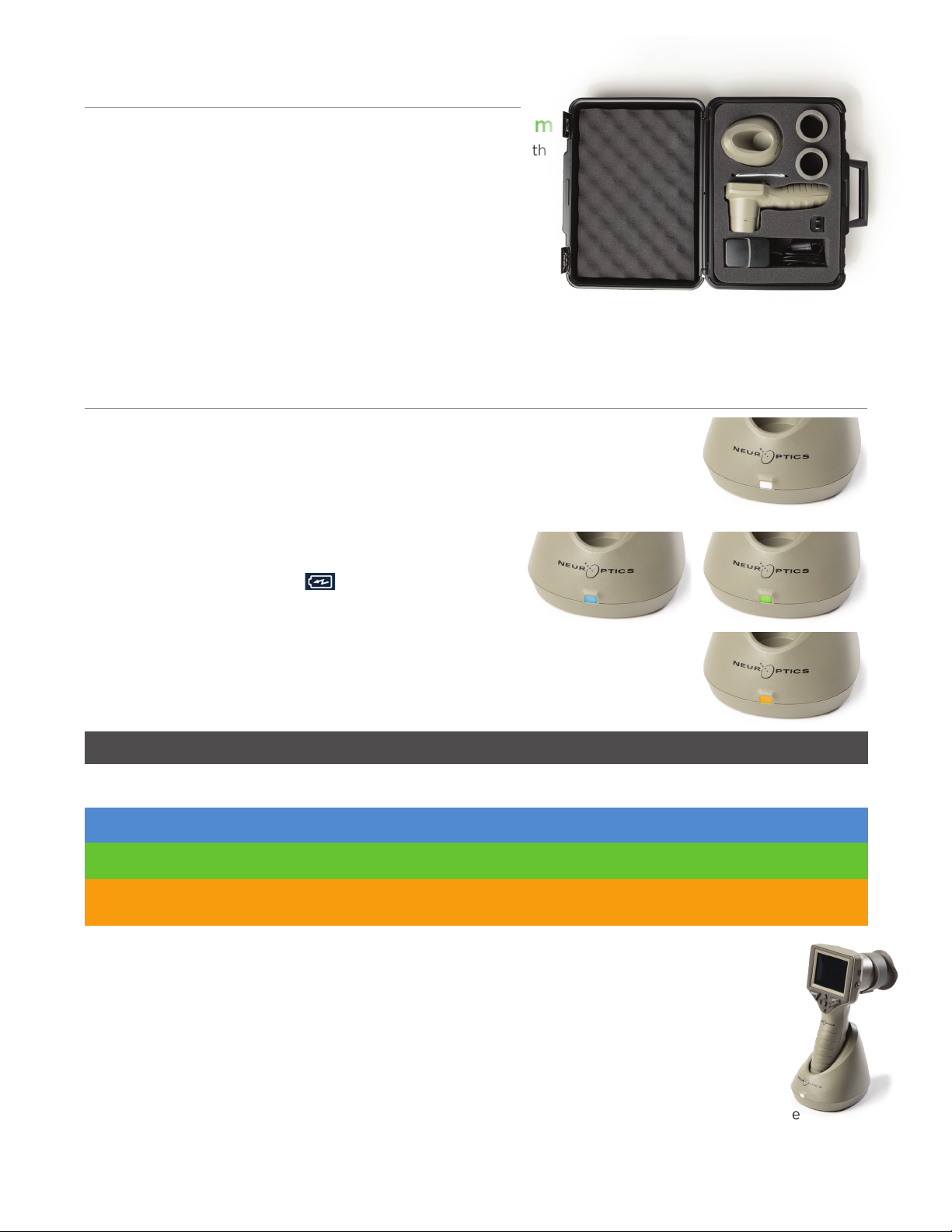
Charging the PLR-4000 Pupillometer
•Connect the PLR-4000 Power Adapter to the Charging Station and plug into
a power outlet. The indicator light at the base of the Charging Station will
display a white color to indicate power has been established to the Charging
Station (Ex. 2).
•Place the PLR-4000 into the Charging Station. The
Charging Station indicator light will turn blue (Ex. 3), and
the LCD screen will display within the battery icon,
indicating the PLR-4000 is charging. The indicator light
will turn green when fully charged (Ex. 4).
•An amber/orange indicator light on the Charging Station indicates a charging
malfunction, and the PLR-4000 will not charge (Ex. 5). If this issue persists,
please contact NeurOptics Customer Service.
Unpacking the PLR-4000 Pupillometer System
The NeurOptics PLR-4000 Pupillometer System is packaged with
the following components (Ex. 1):
The PLR-4000 Pupillometer goes to sleep in the Charging Station to eciently charge:
•The PLR-4000 will initially turn ON (or remain on) upon being placed in the Charging Station.
•
After 2 minutes in the Charging Station, the PLR-4000 will go to sleep to eciently charge. The
screen will go dark (Ex. 6). If any button is pressed or the screen is touched within this 2-minute
window, the time period before the PLR-4000 goes to sleep is extended by an additional 2 minutes.
•To use the PLR-4000 after it has gone to sleep in the Charging Station, simply remove from the
Charging Station, and it will wake up automatically.
•
If the PLR-4000 does not turn on upon being placed in the Charging Station, the battery level may be
too low for normal usage. The Charging Station indicator light should display a blue color, indicating
the PLR-4000 is charging. Leave the PLR-4000 in the Charging Station until it powers on.
Initial Set-Up
•To set up the PLR-4000 for first-time use, please refer to the Power Up section below, ensuring the
PLR-4000 is fully charged and Date/Time are set accurately prior to use.
White Charging Station is plugged into a power outlet, and power has been established.
PLR-4000 is out of Charging Station.
Indicator Light Color Meaning
Blue PLR-4000 is placed in Charging Station and successfully charging.
Green PLR-4000 is fully charged.
Amber/Orange Charging Malfunction – PLR-4000 is not charging. If issue persists, please
contact NeurOptics Customer Service.
Ex. 1
Ex. 2
Ex. 4
Ex. 5
Ex. 6
Ex. 3
•PLR-4000 Pupillometer (A)
•Charging Station (B)
•Power Adapter and Plug (C)
•Eye Cups x 2 (D)
•Data Download Cable
• PLR-4000 Pupillometer Quick
Start Guide
D
C
A
F
B

NeurOptics® PLR®-4000 Pupillometer System—Instructions for Use ©2023 NeurOptics, Inc.
If the PLR-4000 Pupillometer is not in the Charging Station, to conserve battery life it will:
•Go into sleep mode after 4 minutes. To turn ON, touch the screen or push any button.
•Power down after an additional 6 minutes.
Turning On the PLR-4000 Pupillometer
•If the PLR-4000 is out of the Charging Station and has powered down, press
(do not hold) the On/O button on the side of the device (Ex. 7).
•If the PLR-4000 is in the Charging Station and has gone to sleep, simply
remove from the Charging Station, and it will wake up automatically.
Returning to the Home Screen
Press the LEFT or RIGHT buttons (green circles) to return to the Home Screen
(Ex. 11)
.
Measuring Pupils Using the PLR-4000 Pupillometer
5
Ex. 7
Ex. 8 Ex. 9
Ex. 10
Ex. 11
Two components are required to initiate a pupil measurement:
•PLR-4000 Pupillometer (Ex. 12)
•Eye Cup (Ex. 13)
The PLR-4000 should not be used without the eye cup positioned correctly
(Ex. 13) It is very important that the eye cup be correctly fitted. A snug fit helps
reduce the possibility of stray light entering the eye while the scan is taking place.
The eye cup has a tab in the rim which fits into the indentation in the lens shield
of the Pupillometer.
Position the tab in the eye cup rim into the indentation in the lens shield of the
Pupillometer and press into place. The tabs on either side of the lens shield
should also snap into the holes on either side of the eye cup.
Attaching the Eye Cup to the Pupillometer
Ex. 12
Ex. 13
Setting Date and Time
To modify the date and time, from the Home
Screen, select the Settings icon and then
select Date or Time (Ex. 8). Follow the prompts
to input the current date (Ex. 9) and time (Ex. 10)
using 24-hour time configuration and select .
Customers in the United States have the option
to enable Automatic Daylight Savings Time (DST) in the Time settings.
Automatic DST is disabled by default. Automatic adjustments occur based
only on US DST regulations and are not updated according to geographic
location, as the PLR-4000 is not connected to the internet or GPS.
Date and Time Maintenance:
•Regular quarterly maintenance is necessary to ensure date and time
are correct. The set date and time will aect the timestamp listed for
subsequent patient pupil measurements on the PLR-4000. Changing the
date and time will not alter the timestamps on previous measurements.
•Immediately adjust the time after any time change if Automatic DST
is disabled.
NeurOptics® PLR®-4000 Pupillometer System—Instructions for Use ©2023 NeurOptics, Inc.
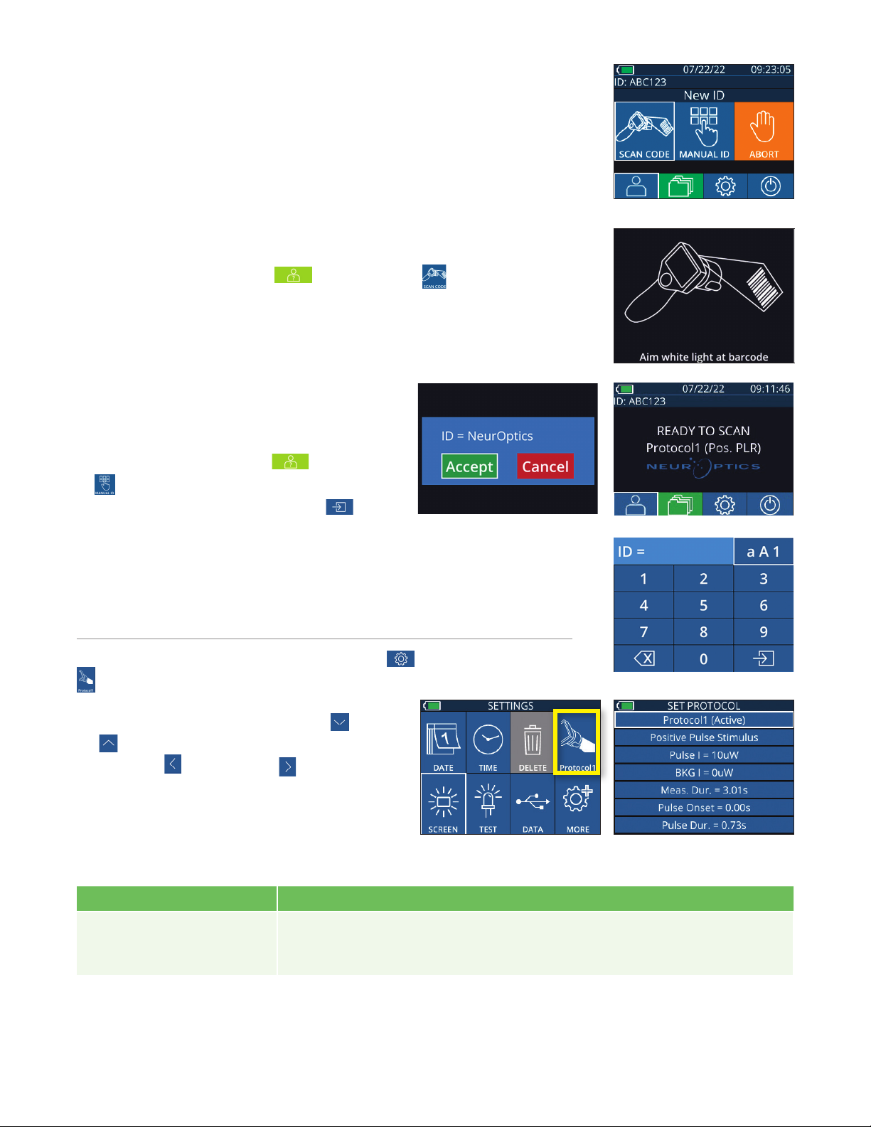
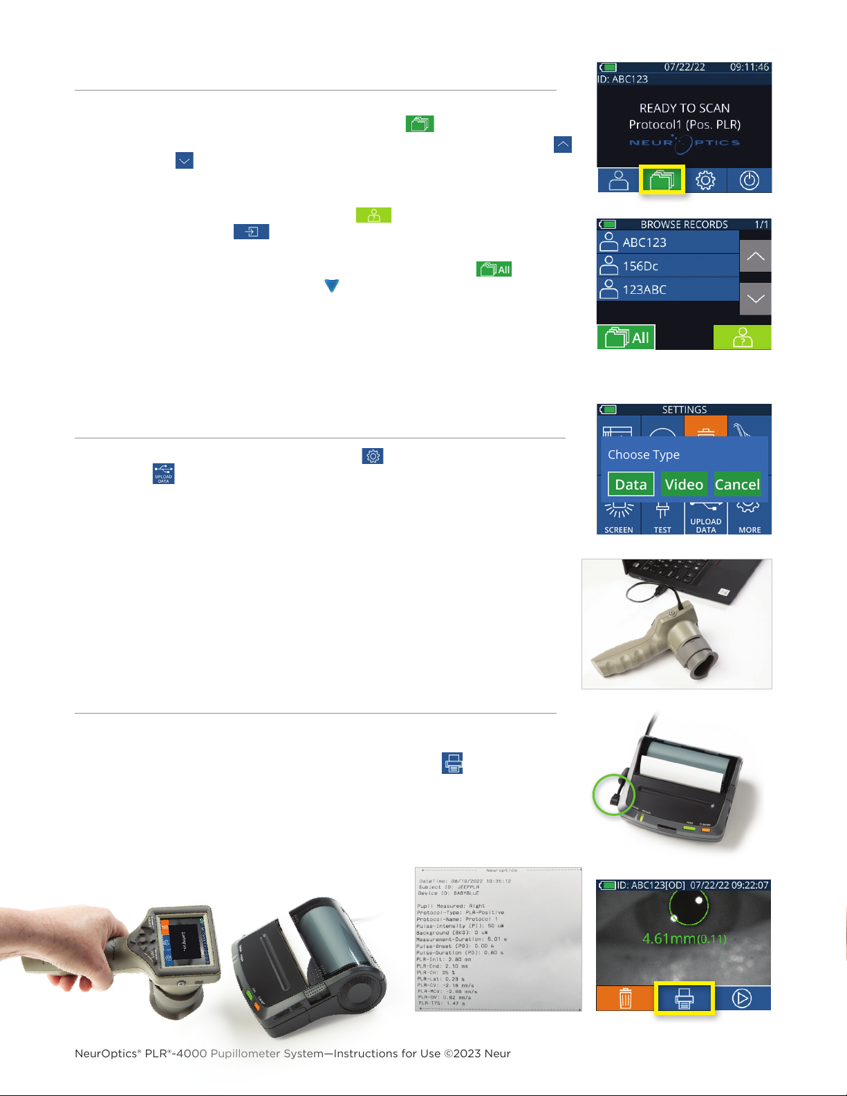
Enter a New Patient ID
There are two options for associating the Patient ID to the Pupillometer:
1) Scanning the patient’s barcode using the PLR-4000 Incorporated Barcode
Scanner, or
2) Manually entering the Patient ID with either alpha or numeric characters (Ex. 14).
Manual Entry of the Patient ID
From the Home Screen select , then Manual
ID . Using the touchscreen or keypad, enter the
alpha or numeric Patient ID and select (Ex.
18). Confirm the patient information on the screen
is correct and select Accept (Ex. 16). The PLR-4000 will display the Patient ID
and read Ready to Scan
(Ex. 17)
.
The characteristics of the light stimulus protocol are summarized in the table below:
6
Ex. 14
Ex. 16 Ex. 17
Ex. 18
From the Home Screen, select the Settings icon and then the top right icon
to navigate to the Set Protocol menu (Ex. 19). Each parameter listed on the
page of this menu (Ex. 20) can be changed by
moving down and up using the DOWN and
UP keys on the directional keypad and then
using the left and right keys keys to toggle
between the values reported. Use the RIGHT or
LEFT key to exit and save the protocol by pressing
YES when asked “Save Changes?”
Set Measurement Protocol
Ex. 20Ex. 19
Ex. 15
Scan Barcode Using Incorporated Barcode Scanner
From the Home Screen, select then Scan Code . The PLR-4000 will
emit a white light from the top of the device (Ex. 15). Center the light over the
barcode until you hear an audible beep. The Patient ID will now appear on the
PLR-4000 touchscreen. Confirm the patient information is correct and select
Accept (Ex. 16). The PLR-4000 will display the Patient ID and read Ready to
Scan (Ex. 17)
.
Parameter Description
Protocol#
Protocols are numbered from 1 to 5. To make a protocol “active”, select the number
(e.g., “Protocol2”) and press the center button on the directional keypad. That
protocol will now show as Active.
Type of protocol
The second setting toggles between 1) “Positive Pulse Stimulus” (light stimulus); 2)
“Static Stimulus”, (no light stimulation and no pupil reflex; “Pulse Intensity” needs
to be equal to the “Background Intensity”); and 3) “Extended”, (no light stimulation,
pupil is recorded continuously for a maximum duration of 10 minutes or until any
button is pressed).
NeurOptics® PLR®-4000 Pupillometer System—Instructions for Use ©2023 NeurOptics, Inc.
Ex. 21
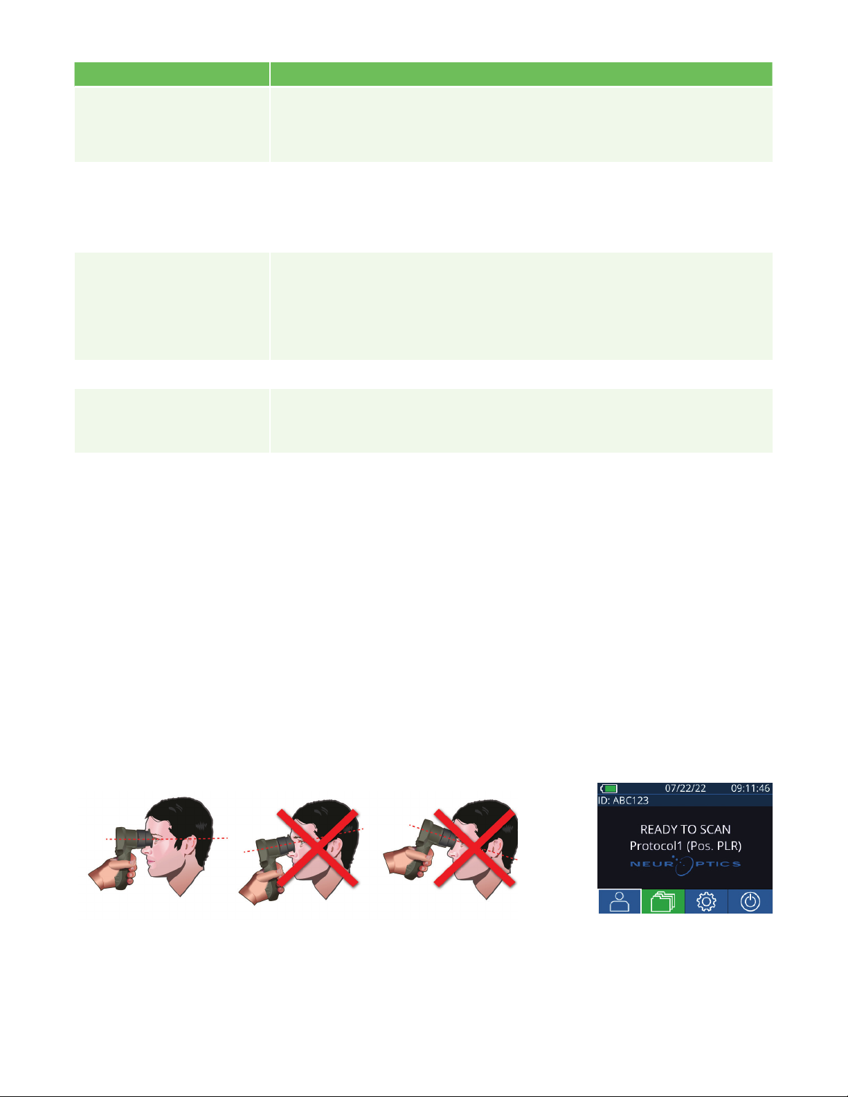
Patient and Environment Preparation
Measurements must be taken when the Pupillometer is on the main measurement screen (Ex. 22) The main
measurement screen shows the date and time, patient ID number, and which Protocol is active: For example,
“Protocol1 (Pos. PLR)” =Positive Pulse Stimulus, “Protocol2 (Static)” =No Limit Stimulus, “Protocol3 (Inf)” =
Extended. The screen should read “READY TO SCAN.”
• Before initiating the measurement scan, turn o or
reduce overhead lighting to ensure that the room
is darkened (if maximum pupil size is desired).
• Instruct the patient to focus on a small target object
(for example, a wall chart or a dim flashing light that
is at least 10 or more feet [3 meters] away) with the
eye that is not being tested. The operator should not
stand in the line of sight between the patient and
the distant target.
• Ask the patient to keep their head straight and
both eyes wide open during both targeting and
measurement. In some cases if targeting becomes
a problem, it may be necessary to gently hold the
patient’s eye open with your finger.
• The operator should position the instrument at a
right angle to the patient’s axis of vision and any
tilting of the instrument should be minimized (Ex 21).
• It may be helpful for the operator to be at the
same level as the patient when performing the
scan to minimize tilting. If necessary, both patient
and operator can sit down facing each other during
targeting and measurement.
Ex. 22
7
Pulse Intensity (PI)
Use this setting to change the intensity of the light stimulus. Units of light emission
power are radiometric, and provided in microWatts (uW). Five dierent intensities
are available for PI: 0uW, 1uW, 10uW, 50uW, 121uW, and 180uW.
Background Intensity (BKG)
Use this setting to change the background light intensity.
Note that in case of a Positive Pulse Stimulus protocol, Background Intensity
must be less than Pulse Intensity, whereas in case of a Static Stimulus protocol,
Background Intensity must be equal to Pulse Intensity.
Measurement Duration
Use this setting to change the duration of the measurement (a minimum of 3 seconds up
to a maximum of 24 seconds.)
Pulse Onset (PO) Use this setting to change the delay of the start of the light stimulus (Pulse).
Pulse Duration (PD) Use this setting to change the duration of the light stimulus (Pulse) (a minimum of
0.03 sec up to the entire duration of the measurement).
Parameter Description

NeurOptics® PLR®-4000 Pupillometer System—Instructions for Use ©2023 NeurOptics, Inc.
8
From the Results screen, select the Video icon to view the video playback of
the reading. Only the last measurement’s video can be played back. Once the
PLR-4000 has powered o, or if the RIGHT or LEFT button is pressed during the
scan, the last video is not accessible (Ex. 28).
Ex. 28
Press and hold either the RIGHT or LEFT button
until the pupil is centered on the touchscreen and
the display shows a green circle around the pupil. A
green frame around the screen indicates the pupil
is properly targeted (Ex. 23), while a red frame
indicates the pupil needs to be re-centered on the
screen before the measurement is initiated (Ex. 24).
Once the green frame appears, release the button, holding the PLR-4000 in place for approximately three
seconds until the results screen is displayed.
Ex. 24
Ex. 23
Results Page for Positive Stimulus
The results page for the Positive Stimulus (Ex. 25) shows the pupil diameter
waveform plotted as a function of time. The two vertical yellow lines show
where the stimulus started and ended. The green vertical line shows the latency
and the blue line the T75. Latency and T75 are two of the variables calculated
by the analysis and they are explained in Appendix A. If a variable could not be
calculated (for example, because of excessive blinking) it is reported with dashes
or in red font in the table.
Results Page for Static Stimulus
The results page for the Static Stimulus (Ex. 26) shows the diameter of the pupil
in bold and the standard deviation of pupil diameter measured (in parenthesis)
during the scan. It also includes the ID number of the subject, the data and time
of the measurement, and finally, which eye (Right or Left) was measured.
Ex. 26
Results Page for Extended Mode
The results page for the Extended Mode shows the whole pupil function as a
function of time (Ex. 27). Colored vertical lines correspond to the five dierent
keys of the direction keypad. The user can press any of those keys during the
recording and the time(s) of the press (or presses) are reported in the plot
and saved with the record. Note that an extended pupil recording is ended
by a press of the RIGHT of LEFT key – the duration of the measurement is not
defined.
Ex. 27
Ex. 25
Video Replay
NeurOptics® PLR®-4000 Pupillometer System—Instructions for Use ©2023 NeurOptics, Inc.
Attach the power supply to the printer as shown in Ex 33. Turn the printer on and
the green light will illuminate. The patient measurement result currently displayed
in the results window (Ex 34) can be printed by selecting the at the bottom of
the screen.
The system will only print a record when a measurement result is displayed on the
screen. If you want to print a measurement other than the last measurement taken,
refer to the “Browse Records” section above. Consult the printer’s instruction
manual for specific printer operation instructions.
Ex. 33
Ex. 34
From the Home Screen, select the Settings icon
,
then select then select
Upload Data . Two choices will appear “Data” or “Video” (Ex 31). If you choose
“Data” a text message will appear on the screen instructing the user to “connect
USB cable & copy R_#####_######.xls.” If you choose “Video” an AVI file will
be saved, and a text message will appear on the screen instructing the user to
“connect USB cable & copy V_#####_######.avi.” Connect the USB cable from
the pupillometer to the computer (Ex 32). The computer will show as “Neuroptics”
drive on the computer. Click on the drive, copy the XLS file or the AVI file and
paste it on your computer. Press “DONE” in the small window on the pupillometer
screen only after the copy has been completed, as the file will then be erased.
Note: Only the last measurement can be downloaded as a video, and it must be
done immediately after a measurement is captured.
To review records stored on the
PLR-4000
:
•From the Home Screen: Select the Records icon (Ex. 29).
•To browse records by Patient ID, select the ID from the list or use the UP
and DOWN arrows on the screen to browse additional IDs available in the
list. The IDs of the most recent measurements taken on the PLR-4000 will
appear at the top of the list.
•To search for a specific Patient ID, select (Ex. 30), then type in the
Patient ID and select .
•To browse all pupil measurements stored on the
PLR-4000
in chronological
order (including all Patient ID’s), select the All Records icon (Ex. 30)
and press the DOWN Arrow button on the keypad to scroll through all
previous measurements stored on the
PLR-4000
.
•When the No more records message appears, the earliest pupil
measurement stored has been reached.
Ex. 30
Ex. 29
The pupillometer stores at least 1,200 measurement in its memory. Once the
memory is full, it begins to write over the oldest measurements first.
9
Ex. 31
Ex. 32
Browse Records
Download Data
Print Data
Sample Printout

NeurOptics® PLR®-4000 Pupillometer System—Instructions for Use ©2023 NeurOptics, Inc.
Settings
Using the touchscreen or keypad, select the Settings
icon (Ex. 37) from the Home Screen to navigate
to the Settings Menu (Ex. 38).
Ex. 38
Ex. 39
Ex. 37
Date and Time
See Setting Date and Time section on Page 5.
Delete Records
To delete records o of the device memory of the PLR-4000, navigate to the
Settings Menu and press Delete ,then select Yes to proceed to delete record
(Ex. 39). Records on the device can be deleted for a specific Patient ID or All Records.
LCD Screen Brightness
The PLR-4000 is defaulted to maximum brightness of the LCD Screen. Adjust to
medium brightness by pressing . Adjust to low brightness by pressing . To
return to maximum brightness, simply press the one more time.
Test LED
Pressing the Test icon demonstrates a sample of the LED light that is emitted from the PLR-4000 when
taking a pupil measurement. The test should show LEDs lit up at 3, 6, 9 and 12 o’clock on the lens side. This test
is for demonstration purposes only and does not aect usage of the device.
Returning to the Main Manu
Press the LEFT or RIGHT buttons (green circles) to return to the Home Screen (Ex. 36).
PLR-4000 Pupillometer Navigation Guide
Ex. 36
Pupil Measurements – Special Considerations
Blinking During Measurement
If the measurement was aected by a tracking problem (e.g., excessive blinking),
then measurement results are all displayed in red font on the results screen and as
“NA” (Ex. 35). In this case, the measurement results are not valid and should not be
relied upon and the measurement should be repeated.
Ex. 35
10
Customize Barcode Scanner
The PLR-4000 Incorporated Barcode Scanner can be customized to truncate
or expand the alpha or numeric characters read from a barcode, if required. The
Default settings automatically adjust to read most types of 1D and 2D barcodes,
and “Default” should remain selected unless a specific customization needs to
be applied to all barcodes scanned by the PLR-4000. Select Settings , more
,Custom Barcode (Ex. 40), then select Scan Sample to scan a sample
barcode and program the required customizations (truncation or expansion) to
be used for all future scans. Contact NeurOptics for additional information.
Ex. 40
System Information
Select System (Ex. 40) to view the PLR-4000’s system information, displaying the Serial Number, Software
Application, and Firmware versions of the device.
NeurOptics® PLR®-4000 Pupillometer System—Instructions for Use ©2023 NeurOptics, Inc.
11
Power O
Ex. 41
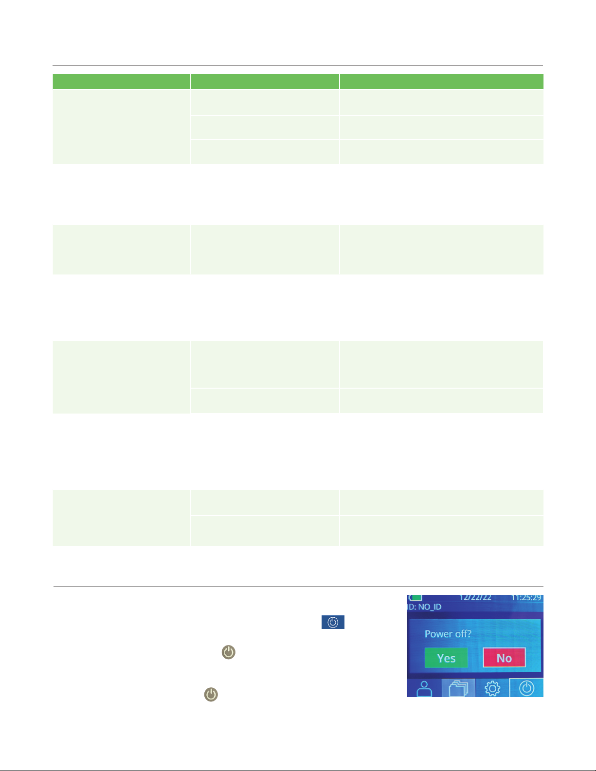
To turn the PLR-4000 Pupillometer OFF, either:
•Navigate to the Home Screen, and select the Power icon , then
confirm Yes to power OFF (Ex. 41).
•Press and hold the On/O button on the side of the PLR-4000 for
about 3 seconds.
The PLR-4000 may occasionally require a System Reboot. To reboot, simply
press and hold the On/O button on the side of the PLR-4000 until it
powers OFF and then power it back on.
Troubleshooting
Issue Possible Reason Solution
1. PLR-4000 Pupillometer
will not turn on
Using incorrect Power Adapter Use only Power Adapter provided with
PLR-4000. Check label on power adapter.
Power cord is not fully plugged into
the wall or the charging station
Check connections.
Battery completely discharged Charge the battery by placing the PLR-4000
into the Charging Station.
2. Pupil measurement will not
initiate after release of the
LEFT or RIGHT key
Too much blinking Gently hold patient’s eye open with your
finger during measurement.
Device not held correctly Hold eye cup at a 90-degree angle to
patient’s face. Make sure patient’s pupil is
centered on the screen.
3. PLR-4000 returned to
Home Screen while taking
a measurement
LEFT or RIGHT button was
pressed while measurement
was being completed, causing
measurement to be aborted
Repeat the scan, ensuring no buttons are
pressed until the scan is completed and
results appear on the screen.
4. Error message appears on
the screen
Various Reboot the PLR-4000 by pressing and
holding the ON/OFF button on the side
of the device until it powers OFF and then
power it back on. If the issue persists, call
NeurOptics Customer Service.
5. “NA” displayed following
measurement
PLR-4000 was moved from
position before measurement
has been completed
Repeat the scan and keep the PLR-4000 in
place until the measurement is completed
and pupillary measurement results are
displayed.
Patient blinking excessively
during measurement
Hold the patient’s eyelid open and repeat the
scan.
6. Download not initiated or
not completed
Cable not well seated inside the
housing of the device
Verify that cable is fully connected to the
PLR-4000 .
Downloaded file does not
appear on the destination
computer
Copy the downloaded file to the computer
before pressing “Done” on the PLR-4000.
7. Measurement results do
not print
The PLR-4000 is not close
enough to the printer.
Make sure PLR-4000 is ≤1m from the printer
PLR-4000 cannot “find” the
printer.
Remove or turn off other devices which may
be interfering with the connection.

NeurOptics® PLR®-4000 Pupillometer System—Instructions for Use ©2023 NeurOptics, Inc.
12
Cleaning Considerations: PLR-4000 Liquid Crystal Display (LCD)
& Lens Cover Glass
For best protection of the liquid crystal display (LCD), and cover glass, use a clean, soft, lint-free cloth and up
to 70% IPA to clean the PLR-4000 optics. Occasional cleaning of the Incorporated Barcode Scanning Window
(located just above the PLR-4000 lens) is also recommended using a clean, soft, lint-free cloth and up to 70%
IPA. Make sure the LCD, barcode scanning window and cover glass appear to be free of debris or water spots.
In instances where there is concern of exposure to highly resistant bacteria, viruses, fungi or spores (ie:
Clostridium dicile, or “C. di”), hospital protocols may require use of cleaning solutions containing sodium
hypochlorite (bleach) when cleaning equipment. If products containing sodium hypochlorite (bleach) are used
to clean the LCD of the PLR-4000, the cleaning process should be followed by a second cleaning using a clean,
soft, lint-free cloth and up to 70% IPA to ensure that all bleach residue is completely removed from the LCD.
Handling, Cleaning and Maintenance
Always handle the PLR-4000 Pupillometer and PLR-4000 Charging Station with care because sensitive
metal, glass, plastic and electronic components are contained inside. The PLR-4000 and Charging Station can
be damaged if dropped or by prolonged exposure to liquid or high humidity environments.
The PLR-4000 and Charging Station do not require any regularly scheduled maintenance or calibration. If the
PLR-4000 and Charging Station are not working properly, or are believed to have been damaged, immediately
contact NeurOptics Customer Service at Toll Free North America: 866.99.PUPIL (866-997-8745), international:
Cleaning the PLR-4000 Pupillometer, Charging Station and Eye Cup
Isopropyl alcohol (IPA)-based cleaning solutions, in formula concentrations up to 70% IPA, are recommended
for use in cleaning the PLR-4000, Charging Station, and eye cup. Do not use chemicals that can damage
the PLR-4000 and Charging Station surface. Some chemicals can weaken or damage plastic parts and may
cause instruments to not operate as intended. Use all cleaning products per manufacturer’s instructions, being
careful to squeeze out excess liquid prior to wiping the PLR-4000 and Charging Station and do not use an
oversaturated cloth.
Wipe all exposed surfaces. Follow the cleaner’s manufacturer instructions as to the time required to leave the
solution on the device surface.
• DO NOT use an oversaturated cloth. Be sure to squeeze out excess liquid prior to wiping the PLR-4000 or
the Charging Station.
• DO NOT allow the cleaner to collect on the instrument.
• DO NOT use any hard, abrasive or pointed objects to clean any part of the PLR-4000 or Charging Station.
• DO NOT immerse the PLR-4000 or the Charging Station in liquid, or attempt to sterilize the product, as
damage to the electronic and optical componentry could occur.
Drying and Inspection Following Cleaning
Confirm the PLR-4000 and Charging Station are thoroughly dry before placing the PLR-4000 back into the
Charging Station.
Customer Service
For technical support, or if you have a question regarding your product or order, please contact NeurOptics
Customer Service at Toll Free North America: 866.99.PUPIL (866-997-8745), international: +1-949-250-9792,
or email: Info@NeurOptics.com.

NeurOptics® PLR®-4000 Pupillometer System—Instructions for Use ©2023 NeurOptics, Inc.
13
Appendix A – Pupillary Measurement Parameters
Parameter Description
INIT = Maximum Diameter Maximum pupil size before constriction (mm)
END = Minimum Diameter Pupil diameter at peak constriction (mm)
DELTA = % Change (INIT-END)/END as a %
LAT = Latency of constriction Time of onset of constriction following initiation of the light stimulus (sec)
ACV = Constriction Velocity
Average of how fast the pupil diameter is constricting measured in millimeters per second
MCV = Maximum
Constriction Velocity
Maximum velocity of pupil constriction of the pupil diameter responding to the
flash of light measured in millimeters per second
ADV = Dilation Velocity
The average pupillary velocity when, after having reached the peak of constriction,
the pupil tends to recover and to dilate back to the initial resting size, measured in
millimeters per second
T75 The time taken by the pupil to recover 75% of the initial resting pupil size after it
has reached the peak of constriction.
Ordering Information
© 2023 NeurOptics®, Inc. NeurOptics® and PLR® are all trademarks of NeurOptics®, Inc. All rights reserved.
Returned Goods Policy
Products must be returned in unopened packages, with manufacturer’s seals intact, to be accepted for credit,
unless returned due to a complaint of product defect or mislabeling. Determination of a product defect or
mislabeling will be made by NeurOptics, which determination will be final. Products will not be accepted for
credit if they have been in the possession of the customer for more than 30 days.
PLR-4000-SYS PLR®-4000 Pupillometer System
NEUR-2059-01 Eye Cup
CBL-0006-00 Data Download Cable
NEUR-PRTS445 Wireless Printer Kit
Parameter Description
Pupillometer Measurement
Detection Threshold
Pupil diameter (minimum) 0.80 mm
Pupil diameter (maximum) 10.00 mm
Change in Size 0.03 mm (30 microns)
Size Accuracy +/- 0.03 mm (30 microns)
Degree of protection against
electric shock
Pupillometer & Eyecup -Type BF Applied Part provided protection
Charging Station & Power Adapter-Type B Applied Part provided protection
Classification of the equipment
against ingress of liquids Ordinary equipment
Appendix B – Technical Specications
NeurOptics® PLR®-4000 Pupillometer System—Instructions for Use ©2023 NeurOptics, Inc.
14
Appendix B – International Symbol Denition
Appendix B – Technical Specications Continued
Degree of safety of application
in the presence of flammable
anesthetic mixture with air or
with oxygen or nitrous oxide
The equipment is not an AP or APG category equipment
Mode of Operation On Demand battery operation
Power Adapter
Input: 100-240 VAC +/- 8%
Output: 6V, 2.8 Amps
RF Wireless Charging Output: 5 W, Qi Compliant
Battery 3.6 V 11.70 Wh 3350 mAh/hour Li: Ion Cell
Operating Environment Temperature Range: 0° C (32° F) to 40° C (104° F)
Relative Humidity: Non-condensing at all times.
Transportation and storage
environment
Temperature Range: -38° C (-36.4° F) to 70° C (158° F) Relative
Humidity: Non-condensing at all times.
Dimensions With Eye Cup = 7.5” H, 3.5” W, 4.5” D
Without Eye Cup = 7.5” H, 3.5” W, 3.5” D.
Weight 344 grams +/- 10 grams
Classification Class 1 LED product per IEC 62471
Parameter Description
Appendix C – International Symbol Denition
Symbol Source/Compliance Title of Description of Symbol
Standard: ISO 15223-1
Symbol Reference No: 5.4.4 Caution
Indicates that caution is necessary when
operating the device or control close to
where the symbol is placed, or that the
current situation needs operator awareness
or operator action in order to avoid
undesirable consequences
Standard: IEC 60417
Symbol Reference No: 5333
Type BF applied
part
To identify a type BF applied part
complying with IEC 60601-1
Standard: IEC 60417
Symbol Reference No: 5840
Type B applied
part
To identify a type B applied part complying
with IEC 60601-1
Standard: ISO 15223-1
Symbol Reference No: 5.1.7 Serial number Indicates the manufacturer’s serial number so
that a specific medical device can be identified
IEC 60417
Symbol Reference No: 5009 Stand-by
To identify the switch or switch position
by means of which part of the equipment
is switched on in order to bring it into the
stand-by condition, and to identify the
control to shift to or to indicate the state of
low power consumption
Standard: ISO 15223-1
Symbol Reference No: 5.2.7 Non-sterile Indicates a medical device that has not been
subjected to a sterilization process
NeurOptics® PLR®-4000 Pupillometer System—Instructions for Use ©2023 NeurOptics, Inc.
15
Standard: ISO 15223-1
Symbol Reference No: 5.1.6 Catalog Number
Indicates the manufacturer’s catalogue
number so that the medical device can be
identified
Standard: BS EN 50419
Article 11(2) of the European
Community Directive 2002/96/
EC (WEEE)
Recycle:
Electronic
Equipment
Identifies product that is subject to the
European Union’s Waste Electrical and
Electronic Equipment (WEEE) 2012/19/
EU Directive for recycling of electronic
equipment. Do not dispose of this product
in unsorted municipal waste stream
U.S. 40 CFR 273.2 European
Community Directive Article 21
of 2006/66/EC
Recycle.
Battery contains
Lithium.
Dispose of according to local procedures
for products containing lithium-Ion batteries
and products containing lithium perchlorate
Standard: ISO 15223-1
Symbol Reference No: 5.1.1 Manufacturer Indicates the medical device manufacturer.
Standard: ISO 15223-1
Symbol Reference No: 5.4.3
Consult
instructions for
use or consult
electronic
instructions for use
Indicates the need for the user to consult
the instructions for use
Standard: ISO 15223-1
Symbol Reference No: 5.3.4 Keep Dry Indicates a medical device that needs to be
protected from moisture
Standard: ISO 15223-1
Symbol Reference No: 5.3.7
Temperature
Limit
Indicates the temperature limits to which
the medical device can be safely exposed
Standard: IEC TR 60878
Symbol Reference No: 5140
Fragile, handle
with care
Indicates a medical device that can be
broken or damaged if not handled carefully
Appendix C – International Symbol Denition Continued
Symbol Source/Compliance Title of Description of Symbol
Standard: ISO 15223-1
Symbol Reference No: 5.7.7 Medical Device Indicates the item is a medical device
Standard: ISO 15223-1
Symbol Reference No: 5.7.10
Unique device
identifier
Indicates a carrier that contains
unique device identifier information
Standard: IEC TR 60878
Symbol Reference No: 5140
Non-ionizing
electromagnetic
radiation
To indicate generally elevated, potentially
hazardous, levels of non-ionizing radiation,
or to indicate equipment or systems
e.g. in the medical electrical area that
include RF transmitters or that intentionally
apply RF electromagnetic energy for
diagnosis or treatment
Standard: IEC TR 60417
Symbol Reference No: 6367
Coin Cell; Coin
Battery
To provide information on packaging that it
contains a small round cell or battery where
the overall height is less than the diameter,
and which contains non-aqueous electrolyte,
for example a lithium cell or battery. To
identify a device related to the power supply
by such cell or battery, for instance a cover
for the battery compartment
Standard: ISO 15223-1
Symbol Reference No: 5.7.8 Translation
Indicates that the original medical device
information has undergone a translation
which supplements or replaces the original
information

NeurOptics® PLR®-4000 Pupillometer System—Instructions for Use ©2023 NeurOptics, Inc.
9223 Research Drive
Irvine, CA 92618 | USA
p: 949.250.9792
Toll Free North America: 866.99.PUPIL
NeurOptics.com
PLR-4000 IFU Rev A (HOMA-BZERFJ)
Parameter Description
Wireless Printing Range Up to 100 cm
Wireless Printing low energy operation frequency 2.4 GHz
Appendix D – Wireless Printing Range and Frequency
Other manuals for PLR-4000
1
Table of contents
Other NeurOptics Medical Equipment manuals


Popular Medical Equipment manuals by other brands

Nutricia
Nutricia Flocare Infinity Short manual

Arden Medical
Arden Medical URIAS 75 000 0 Instructions for use

natus
natus ALGO 3i Instructions for use

Roche
Roche CoaguChek Vantus Quick reference guide

Fukuda
Fukuda LX-8000 Series Service manual

Freedom Innovations
Freedom Innovations Kinnex 2.0 reference guide

RedHealth
RedHealth c. Balance user guide

HeartSine
HeartSine samaritan PAD 450P user manual

Roche
Roche CoaguChek XS System user manual

Johnson & Johnson
Johnson & Johnson Ethicon Echelon Flex instructions

ZERONE
ZERONE ZEUS-100/80 Operation manual

Health Connector
Health Connector zacurate CMS 500DL user manual


