NeuroTherm NT1100 User manual

NEUROTHERM RADIO FREQUENCY LESION GENERATOR
MODEL NT1100®
OPERATORS MANUAL
Document 109.00 10September2012 Issue 06
TABLE OF CONTENTS
1GENERAL INTRODUCTION.........................................................................................................1-1
General Considerations.....................................................................................................................1-1
Indications for Use……………………………………………………………………………………………..1-2
2WARNINGS AND CAUTIONS.......................................................................................................2-1
Warnings...........................................................................................................................................2-1
Cautions............................................................................................................................................2-3
Contraindications...............................................................................................................................2-3
3TECHNICAL DATA .......................................................................................................................3-1
Specification......................................................................................................................................3-1
Earth Leakage...................................................................................................................................3-7
Environmental Conditions..................................................................................................................3-8
Minimising Electromagnetic Interference...........................................................................................3-8
Symbols ............................................................................................................................................3-9
4UNPACKING AND ACCEPTANCE TESTING...............................................................................4-1
Electrical Safety Testing....................................................................................................................4-2
5DESCRIPTION OF THE CONTROLS...........................................................................................5-1
Front Panel Keyboard Layout............................................................................................................5-2
RF Lesion Operation…………………………………………………………………………………………..5-4
Connector Panel Layout………………………………………………………………………………………5-6
Back Panel Layout…………………………………………………………………………………………….5-7
6GETTING STARTED.....................................................................................................................6-1
General description of screen displays..............................................................................................6-1
Setting up the machine for the first time ............................................................................................6-8
Undertaking Simple Procedures................................................................................................... 6-13
Motor and Sensory Stimulation…………………………………………………………………………….6-15
7MORE ADVANCED USE ..............................................................................................................7-1
General terminology, logging, messages and simple operation.........................................................7-1
USB and Printing Records.................................................................................................................7-1
RF Pulse Mode..................................................................................................................................7-6
Pulse Dose........................................................................................................................................7-7
Two electrodes RF ............................................................................................................................7-8
Two Electrode Thermal Lesion..........................................................................................................7-9
Dual Electrode Operation................................................................................................................7-10
Dual Electrode Lesion .....................................................................................................................7-12
Caution............................................................................................................................................7-12
Simplicity II and III Procedure Mode………………………………………………………………………..7-13
Three Electrode RF………………………………………………………………………………………… 7-13

NEUROTHERM RADIO FREQUENCY LESION GENERATOR
MODEL NT1100®
OPERATORS MANUAL
Document 109.00 10September2012 Issue 06
Cordotomy.......................................................................................................................................7-17
Bipolar and Two Bipolar ..................................................................................................................7-18
No Thermocouple Operation ...........................................................................................................7-18
Preset Step Profiles.........................................................................................................................7-19
Custom Step Profiles.......................................................................................................................7-20
Maintenance Screen .......................................................................................................................7-22
8ERROR / ADVICE MESSAGES....................................................................................................8-1
List of Error / Fault Messages............................................................................................................8-1
Hierarchy of Screens.......................................................................................................................8-12
9STERILISATION PROCEDURES .................................................................................................9-1
Cleaning Procedure for the NeuroTherm NT1100 .............................................................................9-1
10 PRINCIPLES OF LESIONING, TYPICAL LESION SIZES AND BASIC PROCEDURES.............10-1
Principles of Lesioning.....................................................................................................................10-1
Simplicity II and Simplicity III Procedure Addendum......................................................................10-10
Typical heat lesion sizes................................................................................................................10-16
Basic Procedures for Stimulation and Lesion ................................................................................10-17
11 MAINTENANCE..........................................................................................................................11-1
12 EC DECLARATION OF CONFORMITY......................................................................................12-1

NEUROTHERM RADIO FREQUENCY LESION GENERATOR 1-1
MODEL NT1100®
OPERATORS MANUAL
Document 109.00 10September2012 Issue 06
1 GENERAL INTRODUCTION
The NeuroTherm Radio Frequency Lesion Generator Model NT1100 has been designed to offer the full
range of features required by all levels of practitioners for pain relief clinic work.
The front panel of the generator which has a series of touch buttons and two rotary potentiometers is
used to provide the clinician with direct manipulation of the stimulation and lesioning functions. An
automatic mode is also provided for various lesioning procedures. The Generator also has an LCD
screen with an integral touch screen. The screen is used to initially select the parameters for treatment
and input information regarding the Doctor, patient and other key information, this information is stored
within the generator and can be printed out on the patient record. During treatment the touch screen
becomes inactive and all control of the NeuroTherm is by the front panel. The screen displays all key
parameters and any treatment profiles.
The generator is designed for safe use in a low light x-ray theatre environment; a remote LCD screen can
be attached via a NeuroTherm Video Unit (NT-VD). This video unit is an optically isolated device which
must be used to avoid any risk to the patient.
At the end of a patient session a patient record is printed out on the NeuroTherm printer. This printer is
not electrically connected to the NeuroTherm, but gets its information via a ‘Bluetooth’ wireless link.
Each printer is matched to a particular NeuroTherm.
The NeuroTherm stores patient records and treatment profiles and holds a large number of the most
recent records in its memory. Records can be downloaded to a NeuroTherm memory Stick (NT-USB) at
any time.
There are a number of safety features in both the hardware and software of the machine to minimise any
risk to the patient. The NeuroTherm has full electronic interlocking to prevent accidental switching to
lesion power or stimulation voltage.
The internal settings of the machine have been factory set and should not be adjusted except by
approved technicians authorised by the company.
The machine is designed for use only with NeuroTherm Thermocouple Probes or probes or catheters
that have been tested for compatibility with the NT1100. A list of compatible probes is on page 2-2. The
use of unapproved probes from other manufacturers could give serious errors in temperature reading
which might compromise the safety of the patient, and would negate the warranty.
Before operating the machine observe the various Warnings and Cautions as detailed in Section 2.
General Considerations
Regularly inspect the accessories of the NeuroTherm, in particular electrode cables should be checked
for possible damage to the insulation.
The accessories are not appropriate for endoscopic use.

NEUROTHERM RADIO FREQUENCY LESION GENERATOR 1-2
MODEL NT1100®
OPERATORS MANUAL
Document 109.00 10September2012 Issue 06
Indications for Use
The NT1100 is intended for use to create lesions in neural tissue. The NT1100 is to be used with
separetly approved lesion/temperature probes such as NeuroTherm radiofrequency probes, Smith &
Nephew Spinecath and Acutherm catheters, and Radionics DiskTrode radiofrequency probes.

NEUROTHERM RADIO FREQUENCY LESION GENERATOR 2-1
MODEL NT1100®
OPERATORS MANUAL
Document 109.00 10September2012 Issue 06
2 WARNINGS AND CAUTIONS
Warnings
A warning indicates a potentially harmful situation to yourself or others.
Ensure you read this Operators Manual before operating the NeuroTherm.
HAZARDOUS ELECTRICAL OUTPUT - The equipment is for use ONLY by qualified medical personnel.
DO NOT under any circumstances perform any Testing or Maintenance on the equipment while it is
being used on a patient.
DO NOT use extension cords or adaptors of any type. The power cord and plug must be intact and
undamaged.
Should the power cord or plug become cracked, frayed, broken or otherwise damaged, it must be
replaced immediately.
If the equipment has in any way suffered mechanical damage, it should be returned to the Supplier for
Inspection and Test before further use.
Unplug the power cord before cleaning or service.
The operator should not perform any servicing of the equipment. Any servicing should only be carried out
by qualified personnel.
EXPLOSION HAZARD – This equipment is not suitable for use in the presence of a flammable
anaesthetic mixture with air or with oxygen or nitrous oxide.
ELECTRIC SHOCK HAZARD – Always turn the equipment off before cleaning and DO NOT allow ANY
fluid to enter the ventilation holes or sockets.
ELECTRIC SHOCK HAZARD – Do not touch any exposed wiring or conductive surface while cover is off
and the equipment is energised. The voltage present when the electric power is connected to the
equipment can cause injury or death. NEVER wear a grounding wrist strap when working on energised
equipment.
FUSE REPLACEMENT – For continued protection against fire hazard, replace only with same type and
rating of fuse as displayed on the rear Serial Number Plate.
IMPROPER LINE VOLTAGE – The Voltage Selector on the mains input socket is factory set and should
not be changed by the user. The Serial Number Plate shows the correct mains input voltage for the
machine and the rating of the fuses to be used in the mains input unit fuse holder. An incorrect voltage
setting may result in NeuroTherm malfunction and potential damage.

NEUROTHERM RADIO FREQUENCY LESION GENERATOR 2-2
MODEL NT1100®
OPERATORS MANUAL
Document 109.00 10September2012 Issue 06
When carrying out treatment take care to avoid the following risks: -
RISK OF RF BURNS TO PATIENT - Ensure patient does not come into contact with metal parts of the
table and its accessories – antistatic sheeting recommended.
RISK OF RF BURNS TO PATIENT - Avoid skin to skin contact between different parts of patient’s body
(for example between the arms and the body of the patient) – use dry gauze if necessary.
RISK OF RF BURNS TO PATIENT: - Avoid using physiological monitoring equipment during a procedure
– if monitoring is required, monitoring electrodes should be placed as far as possible from the
NeuroTherm cannula. Monitoring devices which use needle electrodes are not recommended.
RISK OF RF BURNS TO PATIENT: - Position all cables to the NeuroTherm cannula and dispersive plate
in such a way to avoid contact with the patient or other leads.
INTERFERENCE WITH ACTIVE INPLANTS: - Check whether the patient has a cardiac pacemaker or
other active implant. A possible hazard exists because interference with the action of the pacemaker may
occur or the pacemaker may be damaged. In case of doubt, obtain qualified advice.
INTERFERENCE WITH OTHER EQUIPMENT: - During RF Lesioning procedures the radiated electrical
fields may interfere with other electrical medical equipment. (See Section 3.4 to Minimise
Electromagnetic Interference)
GENERAL CONSIDERATIONS: - Regularly inspect the accessories of the NeuroTherm, in particular
electrode cables should be checked for possible damage to the insulation.
DO NOT USE ENDOSCOPE: - The accessories are not appropriate for endoscopic use.
USE OF FLUIDS: - Ensure that if fluids (saline etc.) are being used during a procedure they should be
positioned away from the NeuroTherm.
RISK OF RF BURNS TO PATIENT: - In Manual Lesion Mode select the lowest possible power for
intended purpose.
RISK OF RF BURNS TO PATIENT: - Check the Dispersive (Neutral) Lead and the Dispersive Pad before
applying power to the patient.
PROBES: - Use only NeuroThermTM, Radionics Disc TrodeTM, SpinecathTM, or ACUTHERMTM probes.

NEUROTHERM RADIO FREQUENCY LESION GENERATOR 2-3
MODEL NT1100®
OPERATORS MANUAL
Document 109.00 10September2012 Issue 06
Cautions
A CAUTION indicates a condition that may lead to equipment damage or malfunction.
Do not activate the output of the NeuroTherm until the probe is properly positioned in the patient.
In monopolar applications, ensure that the Dispersive or return electrode is connected to the patient and
to the NeuroTherm.
Do not remove the top cover of the NeuroTherm, as it will expose voltage which can cause injury or
death.
Servicing of the equipment in accordance with the appropriate service manual should never be
undertaken in the absence of proper tools, test equipment and the most recent revision of the service
manual which is clearly and thoroughly understood.
To reduce risk of electrical shock do not remove the back panel of the NeuroTherm. Refer servicing to
qualified personnel.
When cleaning the outer casing touch panel or screen of the equipment do NOT use abrasive agents or
solvents.
If erratic readings of voltage, current or impedance or temperature are observed, the procedure
should be halted until a determination of the source is identified.
If at any time the device is behaving erratically, press the “Auto Stop” button which will return the device
to a safe state.
Contraindications
Absolute
•Patient unwilling or unable to consent to procedure
•Evidence of untreated infection, either systemic or at proposed surgical site.
•Bleeding diathesis
•Patient medically or psychologically unstable.
•Indeterminate results or diagnostic nerve blocks.
•Pregnancy.
•Patients using anti-coagulants that carry a high risk of bleeding.
•Patients with implanted neurostimulators.

NEUROTHERM RADIO FREQUENCY LESION GENERATOR 2-4
MODEL NT1100®
OPERATORS MANUAL
Document 109.00 10September2012 Issue 06
Relative
•Patients using anti-coagulants whose treatment can be suspended temporarily, or in
whom bleeding can be rapidly and readily reversed, should it occur.
•Patients using pacemaker equipment.
•Anatomical derangements, congenital or surgical that compromise the safe an successful
conduct of the procedure.
•Co-existing disease producing significant respiratory or cardiovascular compromise that
may affect the safe and comfortable conduct of the procedure.
•Immunosuppression.
•Unrealistic patient or family expectations for treatment results.
•Uncooperative patient who is unlikely to tolerate the procedure or comply with post-
operative care instructions.
•Inadequate pain relief or relief for less than three months duration following previous
neurotomy.
(Bogduk, N. (Ed.). (2004). Practice Guidelines for Spinal Diagnostic & Treatment
Procedures.” San Diego, CA. Interventional Spine Intervention Society.)

NEUROTHERM RADIO FREQUENCY LESION GENERATOR 3-1
MODEL NT1100®
OPERATORS MANUAL
Document 109.00 10September2012 Issue 06
3 TECHNICAL DATA
Specification
SIZE
Width 400 mm (15 ¾”)
Height 300 mm (11 ¾”)
Depth 415 mm (16 ½”)
WEIGHT
12.5 Kg. (28 lbs)
ELECTRICAL
Europe 230 Volt 50Hz – 60Hz Fused 1 Amp on live and neutral
USA/Canada 110 Volt 60Hz – 50Hz Fused 2 Amp on live and neutral
Other 220 Volt 60Hz Fused 1 Amp on live and neutral
Voltage change via rear connector
Power Consumption 150 watt
The power supply is built to Class 2 Standard. The mains transformer and all mains
related parts are double insulated from the Main Enclosure. The mains Transformer
has separate isolated bobbins for mains and low voltage windings. Thermal fuses
(rated to fail at 125° C) are fitted into all primary and secondary windings.
The machine is not connected to mains earth (class 2).
STANDARDS
This machine complies with:
EN 60601-1 : 1997
IEC 60601-1-2 : 1993
IEC 60601-2-2 : 1998
IEC 60601-2-10 : with Canadian deviations
With respect to electrical shock, fire and mechanical hazards only in accordance with
UL 60601-1, IEC 60601-1, CAN/CSA C22.2 No. 601.1 and IEC 60601-2-2

NEUROTHERM RADIO FREQUENCY LESION GENERATOR 3-2
MODEL NT1100®
OPERATORS MANUAL
Document 109.00 10September2012 Issue 06
IMPEDANCE
Measuring Frequency 53 KHz (± 3KHz)
Measuring Source Voltage Less than 500 mV AC
Measurement Display 50-2000 ohms (one ohm resolution)
Accuracy ± 5%
Features (a) Internal 500 ohm Test Resistor
(b) Impedance in all Lesion Modes and in Stimulation
Mode when stimulation is off
(c) Audible Tone available where frequency varies
with impedance over full impedance range (50-
2000 ohms). Audible tone is adjustable and
mutable
(d) Warning on screen if impedance is less than 50
ohms or greater than 2000 ohms
STIMULATION MODE
Signal Shape Biphasic square wave with negative edge leading. This
wave is available in a variety of frequencies and widths.
Output Range Voltage 0-5v ± 3% for motor frequencies (2Hz and 5 Hz)
0-3v ± 5% (Default) for all other frequencies
0-0.5v ± 10% for all other frequencies
Current 0-10mA ± 5% 50-2000 ohms
0-6mA ± 5% 50-2000 ohms
0-1mA ± 5% 50-2000 ohms
Pulse Rates Motor 2 or 5 Hz (Default 2Hz)
Sensory 10, 20, 50, 75, 100, 150, 180, 200 Hz (Default 50 Hz)
Pulse Rate Accuracy ± 3%
Pulse Widths 0.1, 0.2, 0.5 and 1.0 mS (Default 1.0 mS)
Pulse width Accuracy ± 5% for 0.2, 0.5 and 1.0 mS
± 15 % for 0.1 mS

NEUROTHERM RADIO FREQUENCY LESION GENERATOR 3-3
MODEL NT1100®
OPERATORS MANUAL
Document 109.00 10September2012 Issue 06
Features (a) Hardware and Software lockout if voltage / current
control not initially set to zero
(b) Warning on screen if stimulation control is not
initially at zero.
(c) Flashing LED on front panel indicates machine is
delivering stimulation pulses
(d) Stimulation Test Socket is provided on front of
machine to interface with the standard stimulation
test kit.
(e) Various screen displays for displaying amplitude of
each stimulation procedure.
LESION MODE
RF Waveform 480 KHz ± 5% Sinusoidal
Power Output Continuously variable. Maximum power output 30 watts
± 5% into 200 ohms. Power is displayed in certain
Lesion Modes.
Voltage Display on screen 0-99RF volts (RMS)
Current Display on screen 0-999RF milliamps (RMS)
Self Test 150 ohm dummy load resistor built into machine
Lamp Indicator LED flashes when Lesion Power is being delivered
Temperature Range Selectable 50 – 90° C for Thermal Lesion (Default 80°C)
Selectable in 5°C steps in initial screen set ups
Selectable in 1°C steps when in Lesion Mode using
Temp up and Temp down’ buttons. In Cordotomy Mode
the Temperature limit can be set to 95ºC (this is only
for Cordotomy)
Time Selectable 0:30 to 10:00 mins (Default 1:00 minute)
Selectable in 30 seconds steps in initial screen set ups
Selectable in 1 second steps when in Lesion Mode
using ‘Time up and Time Down’ buttons
Special Temperature Profiles A series of fixed temperature/time profiles are
programmed into the generator: P1, P2, P3. The user
can also program 3 custom profiles with the following
characteristics: Start Temperature 50-60°C (Default
50°C)
Step Time 00:01 to 3:00 Mins (Default 2 Mins)
Step Rise 1°C , 5°C or 10ºC (Default 5°C)
Final Temperature 65°- 90°C (Default 65°C)Final
Dwell Time 1:00 – 10:00 Minutes (Default 4.00 mins)
Lesion Start Lesion starts as soon as temperature is within 5° of
desired temperature

NEUROTHERM RADIO FREQUENCY LESION GENERATOR 3-4
MODEL NT1100®
OPERATORS MANUAL
Document 109.00 10September2012 Issue 06
Auto Mode With Lesion Power Control Off, the procedure can be
carried out under Automatic control by pressing the
‘Auto start’ button. The temperature will ramp up at 8°C
per second and time will start when the measured
temperature is within 5°C of desired temperature.
The lesioning can be stopped at any time by pressing
the ‘Auto Stop’ Button
Display Temperature is displayed against time as a curve on the
screen together with a display of “Measured
temperature” and “Time to completion of lesion”. RF
Lesion power (or voltage and current ) together with
impedance are also displayed.
Audible Indicator An alarm tone (with a volume adjustment) will indicate
the end of the procedure.
PULSE RF MODE
In pulsed mode the waveform is pulsed rather than continuous.
Pulse Widths 5ms, 10ms, 20ms, 50ms (default 20 ms)
Pulse Frequencies 1Hz, 2Hz, 5Hz, 10Hz, (default 2Hz)
Temperature Range Selectable in 42-65°C range, (default 42°C)
Time Selectable 00:30 to 20:00 minutes (default 2:00 mins)
Set Volts / Current Pulsed RF can be carried out in Auto Mode at fixed
voltages or current.
Voltage range 30-70 Volts (default 45 Volts)
Current range 50-350 mA
PULSE DOSE MODE
In Pulse Dose Mode the number of Pulses of Pulsed RF are counted. Pulse Dose
Procedures are carried out in Auto Mode
Set Temperature 42°C
Pulse Counts 120-1200 count (Default 240 counts)
Rate 2Hz
Width 20 mS
Set Voltage Range 30-70V (Default 45V)
Set Current Range 50-350 mA

NEUROTHERM RADIO FREQUENCY LESION GENERATOR 3-5
MODEL NT1100®
OPERATORS MANUAL
Document 109.00 10September2012 Issue 06
Simplicity II and Simplicity III
This is effectively a multiple probe that can be used in Radio Frequency Lesion treatment of
the (SI) Sacroiliac Joint.
Note to Use the Simplicity Functionality, the auto dispersive must be on. This is
activated from OPTIONS from the Welcome screen select “MORE“ Press auto
dispersive ON. Press finish to return to the welcome screen
The Procedures are automatic in lesion mode and start by pressing the auto-start Button
Stimulation is carried as for normal Motor and Sensory tests
Simplicity II is for use with patients that have short SI joint (no S4) the procedure is: -
From the Procedure Setting Screen select Simplicity II or Simplicity III from the electrode
Selection Screen. Press Accept to return to the Procedure Settings Screen
Stimulation is carried as for normal Motor and Sensory tests
The Lesion is automated and will operate as follows; -
The dual electrode lesion is performed between electrode 1 and 2, the next lesion is to
electrode1 followed by a further lesion to electrode 2. There is a short time delay between
lesions to allow the lesion area to reduce in temperature.
The Simplicity II procedure is complete after the tone sounds and the RF is switched off.
Simplicity III is for use with patients that have a longer SI joint.
The Auto Dispersive must be on. Before the procedure is performed
The Procedures are automatic in lesion mode and start by pressing the auto-start Button
From the Procedure Setting Screen select Simplicity III from the electrode selection screen.
Press Accept to return to the Procedure Settings Screen
Stimulation is carried as for normal Motor and Sensory tests
A Dual electrode lesion is produced between electrode 1 and 2, a further lesion is performed
between electrode 2 and 3,
The next lesion is carried out at electrode 1 then at electrode 2 and then electrode 3. There is
a short time delay between lesions to allow the lesion area to reduce in temperature.
The Simplicity II procedure is complete after the tone sounds and the RF is switched off
See Addendum on NT1100 Simplicity II and III Section Number 10-11.

NEUROTHERM RADIO FREQUENCY LESION GENERATOR 3-6
MODEL NT1100®
OPERATORS MANUAL
Document 109.00 10September2012 Issue 06
MULTIPLE PROBES
The NeuroTherm can be operated with 1,2 or 3 probes. When in Stimulation Mode
each probe is selected by the operator for Stimulation. In RF Lesion, Pulse RF or Pulse
Dose Mode the generator energises all connected probes in a time interlacing method.
In multiple probe operation not all pulse rates are available.
Features (a) Hardware and Software lockout if RF Power
Control not initially set to zero.
(b) Warning on screen if RF Control is not initially set
to zero or if Auto is selected and RF control is not
off.
(c) LED Flashes on front panel to indicate machine is
delivering power.
(d) Three output sockets to accept a variety of probes,
(including Cordotomy (optional extra)) and enable
multiple probe operation.
(e) Hardware lockout if temperature exceeds 95°C.
MAJOR FEATURES
Touch Screen Operation – User interface set up and software control via TP 400
Processor.
Windows CE4.2.NET Operating System.
12.1” LCD Screen with Back lighting and wide antiglare visibility.
Printer Support Via Bluetooth adaptor internally fitted.
Remote Mimic Screen Optically isolated running over CAT5 Cable to External
TFT screen up to 300 metres.
Storage Device USB Memory Stick for downloading log files.
Service Ports Only accessible by service engineers for keyboard +
mouse
Any equipment connected to rear socket must comply with IEC60950 and IEC60601-1
Use only parts supplied by NeuroTherm Ltd. Any other parts will void the warranty and
may cause danger to the patient.
NEUROTHERM RADIO FREQUENCY LESION GENERATOR 3-7
MODEL NT1100®
OPERATORS MANUAL
Document 109.00 10September2012 Issue 06
Earth Leakage
Typical
Maximum Allowable
1
Enclosure leakage current
Normal
Reverse
Single Fault Condition
Normal
Reverse
40 microamps
40 microamps
40 microamps
40 microamps
100 microamps
100 microamps
500 microamps
500 microamps
2
Patient leakage current
Normal (AC)
Reverse (AC)
Single fault condition
Normal (AC)
Reverse (AC)
5 microamps
4 microamps
7 microamps
7 microamps
100 microamps
100 microamps
500 microamps
500 microamps
3
Patient Leakage current
Normal (DC)
Reverse (DC)
Single fault condition
Normal (DC)
Reverse (DC)
4 microamps
4 microamps
4 microamps
4 microamps
10 microamps
10 microamps
50 microamps
50 microamps
4
Patient Auxiliary Leakage Current
Normal (AC)
Reverse (AC)
Single Fault Condition
Normal (AC)
Reverse (AC)
4 microamps
4 microamps
6 microamps
6 microamps
100 microamps
100 microamps
500 microamps
500 microamps
5
Patient Auxiliary Leakage Current
Normal (DC)
Reverse (DC)
Single Fault Condition
Normal (DC)
Reverse (DC)
4 microamps
4 microamps
4 microamps
4 microamps
10 microamps
10 microamps
50 microamps
50 microamps
6
Patient Leakage Floating Type
Normal
Reverse
Single Fault Condition
Normal
Reverse
27 microamps
27 microamps
36 microamps
35 microamps
5000 microamps
5000 microamps
5000 microamps
5000 microamps

NEUROTHERM RADIO FREQUENCY LESION GENERATOR 3-8
MODEL NT1100®
OPERATORS MANUAL
Document 109.00 10September2012 Issue 06
Environmental Conditions
7
Transport
Temperature
Humidity
Pressure
-10°C to 70°C
0-95% RH
140-760mmHg
Non-Condensing
(0-12,200 metres)
(0-40,000ft)
8
Storage
Temperature
Humidity
Pressure
10°C to 60°C
10 to 80% RH
520-760mmHg
(0-3000 metres)
(0-10,000ft)
9
Operating
Temperature
Humidity
10°C to 40°C
10 to 80% RH
IMPORTANT NOTICE
To comply with the Waste Electronic Equipment Regulations (WEE), at the end of the equipment’s
life, the NeuroTherm unit should be returned to the manufacturer NeuroTherm for safe disposal of
the electronic components. (The return addresses are shown in section 11-1 of this manual).
Minimising Electromagnetic Interference
Although the NeuroTherm NT1100 meets the EMC requirements for a device of this type, it is
good practice to follow certain guidelines to minimise the risk of interference between the
NeuroTherm and other devices.
1 Do not twist the cable of the NeuroTherm with those of other devices
2 Avoid putting the NeuroTherm on top of other operating equipment or other
operating equipment on top of the NeuroTherm
3 The NeuroTherm generates 480 KHz at up to 30 watts during the RF Lesion
Treatment phase. If any interference occurs to other equipment, it will be most
noticeable under this condition.
To check this, connect the 200 ohm Test Box into the machine, turn to full power in RF Lesion
Mode and observe any reading changes or interference on other equipment.
To minimise any interference, position the NeuroTherm as far away as possible from the device
being interfered with.
NEUROTHERM RADIO FREQUENCY LESION GENERATOR 3-9
MODEL NT1100®
OPERATORS MANUAL
Document 109.00 10September2012 Issue 06
F
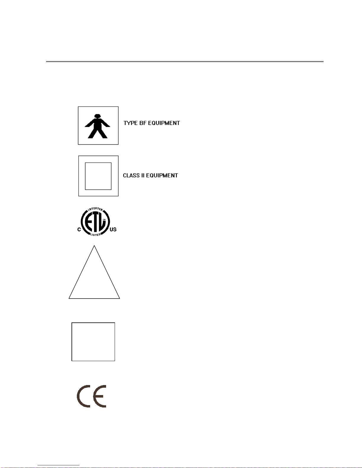
Symbols
The following symbols are displayed on the machine and the meaning of them is shown
below
ETL Mark
0086 CE mark
!
Attention: Consult accompanying
documents
Floating output (not connected to ground)
NEUROTHERM RADIO FREQUENCY LESION GENERATOR 4-1
MODEL NT1100®
OPERATORS MANUAL
Document 109.00 10September2012 Issue 06
4 UNPACKING AND ACCEPTANCE TESTING
ON RECEIPT, THE MACHINE SHOULD BE UNPACKED AND INSPECTED FOR ANY
PHYSICAL DAMAGE.
Check that the voltage shown on the rear Serial Number Plate matches the local supply, if not,
contact your local distributor. Do not attempt to alter the voltage selector on the rear of the
machine. This is for factory setting only.
Place the NeuroTherm on a flat surface, connect the machine into the mains and switch on using the
ON/OFF switch on the rear of the machine. The following will be observed:
a) The Mains LED will light
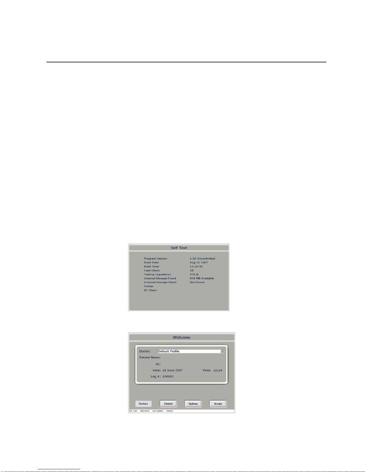
b) After a few seconds (during which the computer within the NeuroTherm is going
through a boot sequence) the machine will display the “Self Test” Screen and go
into a self-test routine. As each test is completed the results will be shown on
screen. Upon the completion of all internal tests the Self Test Screen will display
its results for a few seconds.
c) Should a test fail the unit will stop at the fail point with a Warning Message
d) Check Power inlet fuses and Contact NeuroTherm at address in the service section
of this manual
The NeuroTherm will then switch on its “Welcome” Screen
The NeuroTherm is now ready for use. Refer to Section 6 on Getting Started

NEUROTHERM RADIO FREQUENCY LESION GENERATOR 4-2
MODEL NT1100®
OPERATORS MANUAL
Document 109.00 10September2012 Issue 06
Electrical Safety Testing
If an Automatic or Manual Electrical Safety Analyser is used, the following settings must be used:
Machine Class: Class II Type BF
To test the various leads of the output, use the following plugs:
Dispersive plug (4mm Safety Socket)
One of the active Plugs (Lemo 4 pin)
There is no specified EARTH REFERENCE POINT as the output is floating and could possibly
induce operational errors. If an Earth point is needed, attach onto any of the four allen cap bolts
on the rear of the machine.
NEUROTHERM RADIO FREQUENCY LESION GENERATOR 5-1
MODEL NT1100®
OPERATORS MANUAL
Document 109.00 10September2012 Issue 06
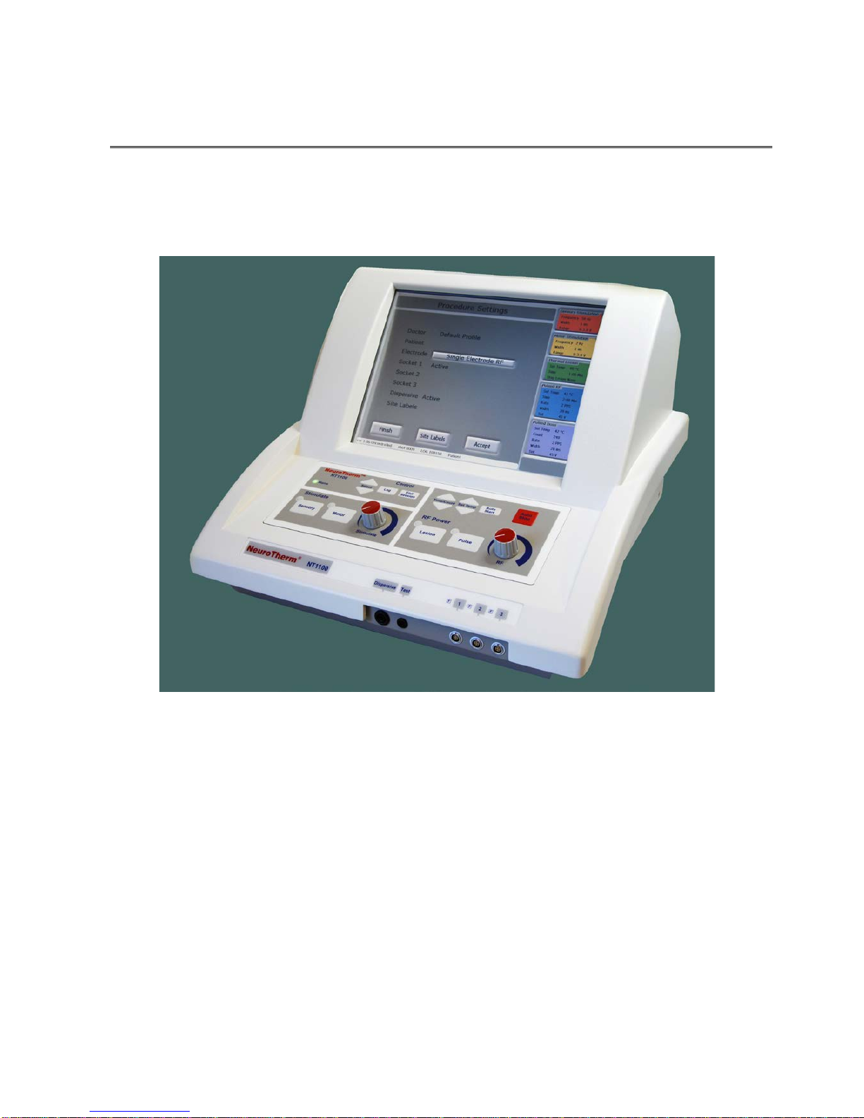
5 DESCRIPTION OF THE CONTROLS
The NeuroTherm NT1100 viewed from the front is shown below
In operation, control of the generator is via a Front Panel Keyboard and the screen will show the
current settings of the machine, what is being delivered to the patient and any error or warning
messages.
In set up mode when the generator is not connected to the patient the screen is transformed into a
touch screen, and a whole series of conditions can be set up including parameters for treatment,
Doctor and patient details. This information then forms part of the patient treatment record which
can be printed out (and downloaded to a memory stick) at the end of a treatment session.
When the screen is in touch screen mode the Front Panel Keyboard is inactive and when the
screen is in display mode the Front Panel Keyboard is active.
Table of contents
Popular Medical Equipment manuals by other brands


Getinge
Getinge Arjohuntleigh Nimbus 3 Professional Instructions for use

Mettler Electronics
Mettler Electronics Sonicator 730 Maintenance manual

Pressalit Care
Pressalit Care R1100 Mounting instruction

Denas MS
Denas MS DENAS-T operating manual

bort medical
bort medical ActiveColor quick guide

AccuVein
AccuVein AV400 user manual


