Smappee Energy monitor-e1 User manual

English – Version 1.0 – April 2020
Smappee Energy
Installation manual

Smappee Energy – Installation manual - English
2
Table of contents
1.
Safety instructions 3
2.
How to install 5
3.
Physical installation 6
4.
Cloud connection and setup 11
5.
Validation of the installation 12
6.
Three-phase voltage and current mapping 13
A
ddendum 1 – Colour code explanation 16
A
ddendum 2 – Wi-Fi connection properties
and firewall rules 17
Smappee Energy – Installation manual - English
3
1. Safety instructions
Safety warning
Carrying out electrical work in a home or workplace can be dangerous.
Only certified electricians may carry out the installation, which must be in accordance
with the national safety regulations.
Safety precautions
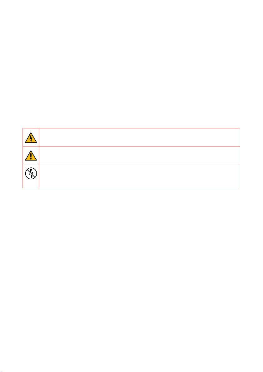
CAUTION: Risk of electric shock.
CAUTION: Refer to the accompanying documentation whenever you see
this symbol.
DO NOT clamp or pull out NON-INSULATED conductors carrying
DANGEROUS VOLTAGE which could cause an electric shock, burns, or arc
flash.
Please observe the following safety precautions to avoid potential electric shock, fire,
or personal injury:
• Use this product only for its intended purpose.
• Use the product indoors only.
• Do not open the equipment or touch any of its electronic circuitry.
• Do not attempt to open, repair or service any parts. Only certified electricians can
perform reparations.
• Only use specified replacement parts.
• Only use the cables and power cords delivered with the product.
• Do not use damaged current transformers, power cords or cables. Make sure the
insulation isn’t damaged and the metal isn’t exposed. Check the connection of the
power cords.
• Do not immerse the product in water or any other liquids.
• Do not expose the product to heat, flame, or extreme cold.
• Do not connect the product to voltages higher than 240 V.
• Power off the electrical installation before proceeding with the physical
installation.

Smappee Energy – Installation manual - English
4
Product identification
• Smappee Energy: monitor-e1
Maintenance
• Clean the outside only with a dry, clean cloth.
• Do not use abrasive agents or solvents.
Responsibility
• Assembly, connection, and use must be carried out in accordance with the
installation standards currently in force.
• The device must be installed in accordance with the instructions given in this
manual.
• Failure to observe the instructions for installing this unit may compromise the
device’s intrinsic protection.
• The device must be placed in a system that complies with the applicable standards
and safety regulations of the country of installation.
Explanation of the safety symbols
Class II equipment does not require an earth connection.
Support
If you have any questions, please contact your local distributor.

Smappee Energy – Installation manual - English
5
2. How to install
The installation procedure consists of the following steps:
Physical installation: The physical installation of all the Smappee Energy
components.
Cloud connection and setup: The creation of a location, its properties, and the
loads to be measured.
1. Validation of the installation: Checking the accuracy of live power values.
This procedure is done with the Smappee Energy Monitor mobile app.
1
2
3
Smappee Energy – Installation manual - English
6
3. Physical installation
This procedure describes the required steps for the physical installation of the Smappee
Energy.
WARNING: For safety purposes, it is necessary to power off the installation
before proceeding with the physical installation.
The Smappee Energy can be used to measure the following loads:
• Single Phase - 1P (1 * 230 V): total consumption
• Single Phase - 1P (1 * 230 V): total consumption and production (E.g. Solar
production)
• Three Phase - 3P+N (3 * 400 V) and 3P (3 * 230 V): total consumption
Steps
Power off the installation and open the fuse box.
Connect the current transformers (CTs) according to the connection diagram, see
next pages.
Position the monitor near the fuse box and a wall socket. You can just place it or
mount it on the wall using two screws.
Close the fuse box and power in the installation.
Connect the supplied power cord to the monitor and plug the power cord in the
nearby wall socket to power on the Smappee monitor.
Proceed in the Smappee Energy Monitor mobile app and follow the steps as shown.
1
2
3
4
6
5
Smappee Energy – Installation manual - English
7
Make sure there’s a stable Wi-Fi connection at the location of installation.
Smappee Energy is only compatible with 2.4 GHz Wi-Fi networks.
Make sure the Wi-Fi network is online when powering on the Smappee
monitor.
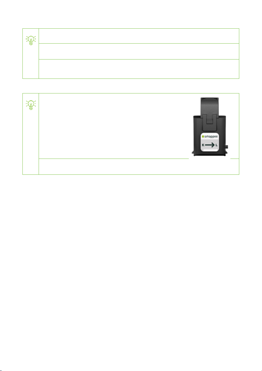
The arrow indicated on the CT (K > L) must point in the
direction of the current flow:
• Consumption: away from the utility meter,
towards the consumers (fuses).
• Solar: away from the inverter, towards the
consumers.
Mount the CTs around the phase wires.

Smappee Energy – Installation manual - English
8
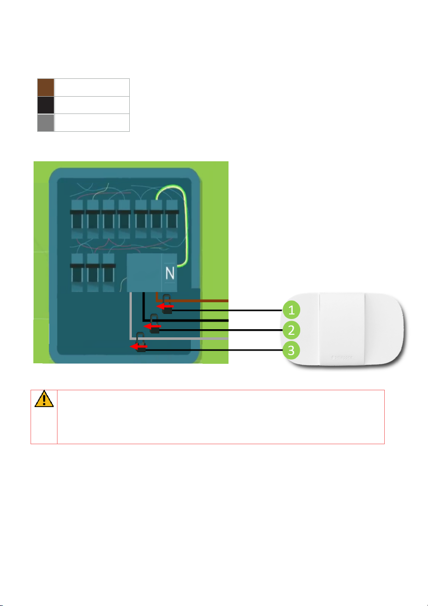
Connection diagram – 1P (1 * 230 V)
Brown – L1
Blue – Neutral
Connect the CTs to the Smappee Energy:
• Input 1: Consumption
• Input 2: Solar
• Input 3: Do not use
Use a digital multimeter to determine the phase wire
of the solar inverter.
0 volt is measured when both loads are on the same phase.

Smappee Energy – Installation manual - English
9
Connection diagram – 3P+N (3 * 400 V)
Brown – L1
Black – L2
Grey – L3
Blue – Neutral
WARNING: For a three-phase installation it is mandatory to setup the voltage
and current mapping in the Expert Portal (see next pages).
Incorrect line voltage and current mapping may result in incorrect reporting of
the power values and monitored data.
Smappee Energy – Installation manual - English
10
Connection diagram – 3P (3 * 230 V)
Brown – L1
Black – L2
Grey – L3
WARNING: For a three-phase installation it is mandatory to setup the voltage
and current mapping in the Expert Portal (see next pages).
Incorrect line voltage and current mapping may result in incorrect reporting of
the power values and monitored data.

Smappee Energy – Installation manual - English
11
4. Cloud connection and setup
This procedure is done with the Smappee Energy Monitor mobile app. The first step is
creating a location and defining the measured loads and their properties.
• Log in to the Smappee App with the corresponding Smappee username or create a
new account.
• Create a new location.
• Follow the steps shown in the mobile app.
To add a new location under the same user account in the mobile app, go
to Settings > Your Locations > Add a new location.

Smappee Energy – Installation manual - English
12
5. Validation of the installation
Once the installation is complete, it is good practice to validate the correct operation of
the monitoring solution.
You should check that all CTs are operational and measuring the correct power values.
To check the correct operation of the Smappee Energy, Smappee provides real-time
values of the measured loads. You can access these real-time values with the mobile
app.
The Smappee App reports real-time active power values. Consumption is
displayed in the yellow bubble. Production is displayed in the green bubble. If
no production is measured, the green bubble is not displayed.
WARNING: For a three-phase installation it is mandatory to setup the voltage
and current mapping in the Expert Portal (see next pages).
Incorrect line voltage and current mapping may result in incorrect reporting of
the power values and monitored data.
Smappee Energy – Installation manual - English
13
6. Three-phase voltage and current
mapping
This procedure describes how to validate and adjust phase mapping for three-phase
installations. This procedure is mandatory for three-phase installations.
Open the Smappee App, go to Settings > Your Smappee Monitors > Expert Portal and
type the website link (http://<IP-address>/Smappee.html) in your internet browser on
your laptop or pc. Log in with the default password: admin.
Go to Configuration > Phase to input mapping
• Power on multiple appliances (resistive loads) until you reach a power
consumption greater than 200 W on each of the phases. E.g turn on the lights,
an electric heater, an electric oven, a coffee machine, a hair dryer.
• Uncheck the ‘Auto Detection’ checkbox.
• Select each of the 6 options in the Phase to input mapping and click on Test
setting to temporarily activate the selected option.
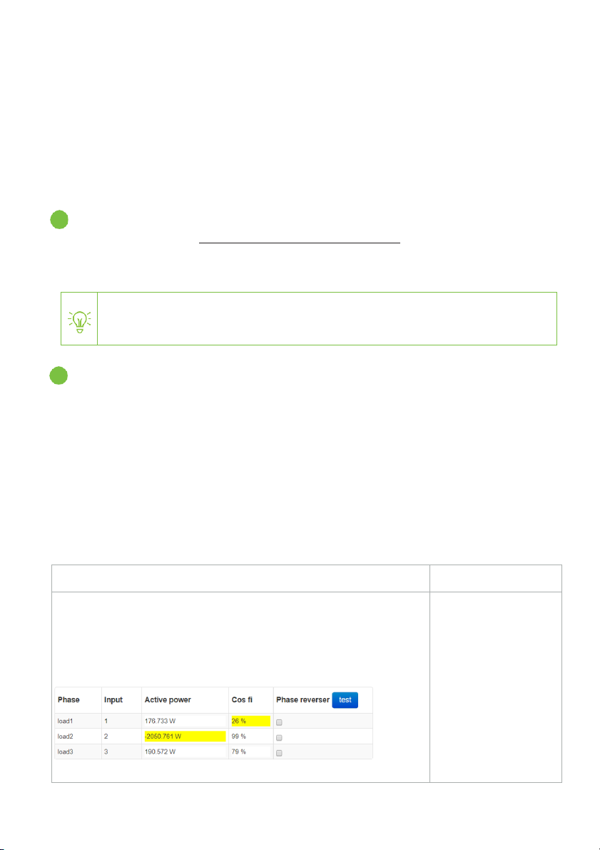
• Choose the phase mapping which is the best possibility: verify whether the
active power values are correct, the power values are positive and the high Cos
Fi values are high enough (> 80 %).
Possibility
Feedback
• Two or three active power values are lower than the real
power consumption.
• Or two or three active power values are negative.
• One or more Cos Fi value is lower than 80%.
E.g.
This phase mapping
seems to be incorrect.
Continue to find the
correct configuration.
You need to be on the same Wi-Fi network as the Smappee Energy to connect
to the Expert Portal.
1
2
Smappee Energy – Installation manual - English
14
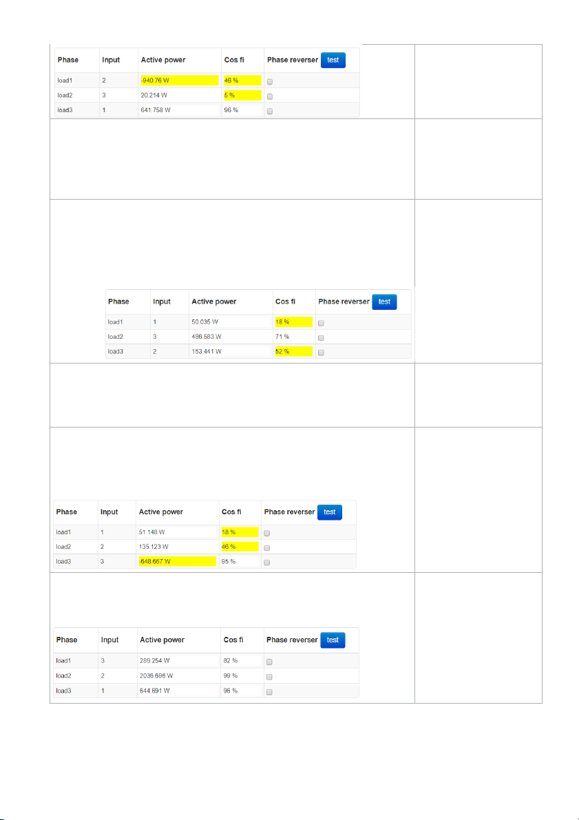
• Absolute power values are correct.
• Three active power values are negative.
• All Cos Fi are higher than 80 %.
This phase mapping
seems to be correct
but you need to
reverse the voltages
(see next step).
• Three active power values are lower than the real power
consumption.
• Three active power values are positive.
• All Cos Fi are higher than 80 %.
E.g.
This phase mapping
seems to be incorrect.
Continue to find the
correct configuration.
• Absolute power value is correct.
• Three active power values are negative.
• All Cos Fi are higher than 80 %.
This phase mapping
seems to be incorrect.
Continue to find the
correct configuration.
• Three active power values are positive
• Two Cos Fi are higher than 80 %.
• One Cos Fi is lower than 80 %.
E.g.
This phase mapping
seems to be incorrect.
Continue to find the
correct configuration.
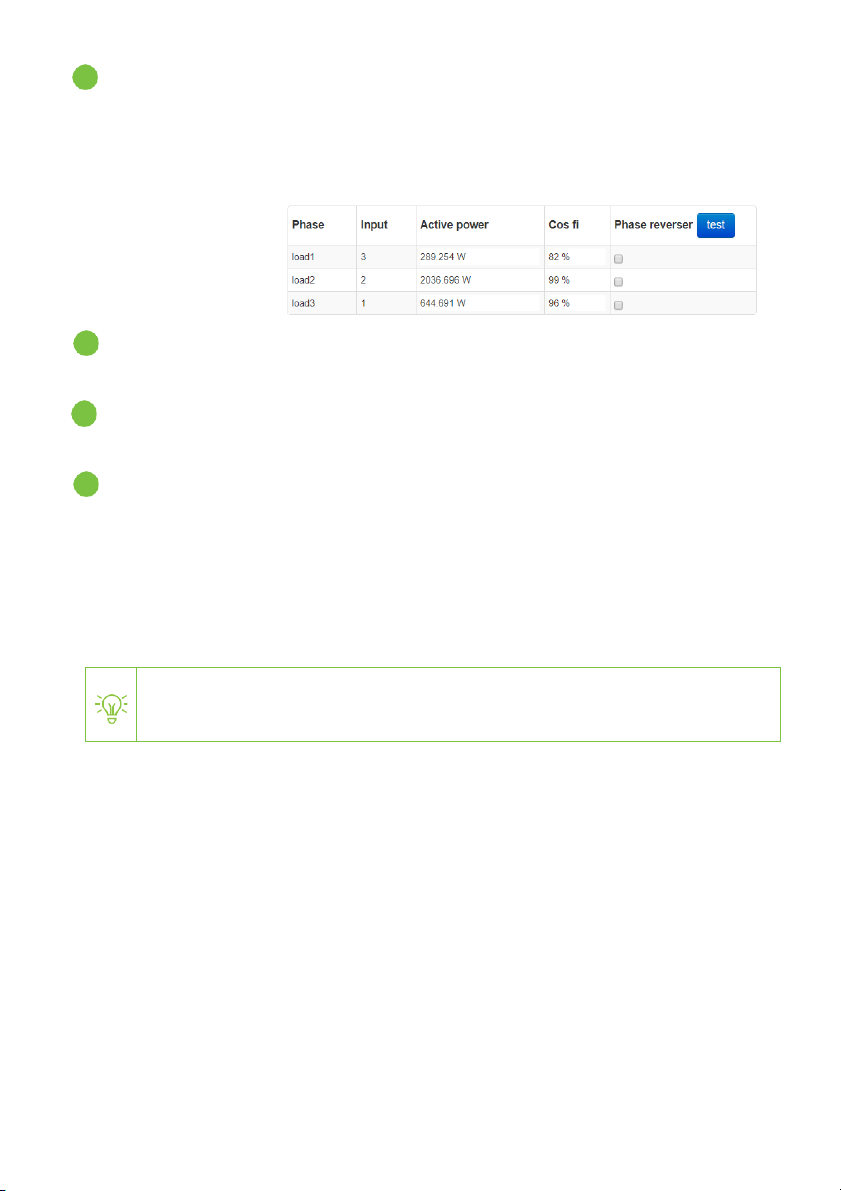
• Three active power values are positive.
• All three Cos Fi are higher than 80 %
E.g.
This phase mapping
seems to be correct.
This is the best
possible configuration.
Smappee Energy – Installation manual - English
15
Voltage reversing (optional)
• If all 3 input voltages remain negative after the phase mapping changes,
reverse them by clicking ‘run voltage reverser’.
• If due to circumstances, one or more CTs could not be installed in the correct
direction, please reverse the input using the Phase reverser checkbox.
Press ‘test’ to
update the
change(s)
temporarily.
Click ‘save changes and restart metering engine’. Otherwise, the changes to the
configuration will not be saved.
Validate the configuration. Refresh (press F5) the webpage and log in again to the
Expert Portal to see if all changes are saved and the configuration is correct.
Final check:
• Activate a high consuming appliance of which you know the power
consumption. E.g. vacuum cleaner or coffee machine.
• Verify the power increase in the yellow bubble in the Smappee App. If this is not
correct, the phase mapping is incorrect.
• If you are not able to get the correct configuration, please contact your local
distributor.
Inform your local distributor if you have doubts about your phase mapping.
3
4
5
6
Smappee Energy – Installation manual - English
16
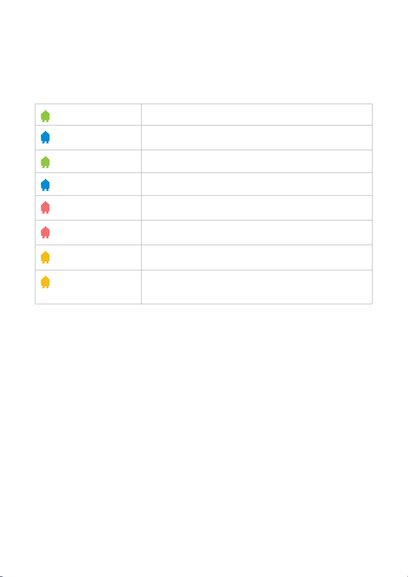
Addendum 1 – Colour code
explanation
Green breathing
All good. The monitor is working correctly.
Blue Steady
The monitor is starting up. This may take up to 5 minutes.
The light may briefly go off during that time.
Green Steady
Connected to the Wi-Fi and the local network (i.e. the Wi-Fi
password is correct)
Blue Flashing
The monitor is ready to be connected to the local Wi-Fi
network.
Red Steady
The monitor has no connection to the internet during
startup. Connection issue.
Red Flashing
The monitor had a working internet connection but has lost
its connection to the Smappee cloud.
Yellow Steady
The Wi-Fi hotspot access point has been activated to allow
the Monitor to reconfigure the Wi-Fi settings.
Yellow Flashing
The monitor is trying to open a Wi-Fi hotspot access point.
Please wait a few seconds. The light will turn to a steady
yellow in a few moments.
Smappee Energy – Installation manual - English
17
Addendum 2 – Wi-Fi connection
properties and firewall rules
Wi-Fi Connection properties
• 2.4 GHz Wi-Fi required, preferably with automatic channel selection
• Networks without DHCP server are not supported
• WPA or WPA2 encryption mandatory
• Networks without security are not supported (!)
• SSID must be visible and should not be hidden during installation. SSID must NOT
contain the following characters: é,ç,è,ä,/\, “, à î ô ï
• Allowed special characters for the Wi-Fi password: #$%@?/ \
• MAC filtering must not be active on the router
• Your firewall should allow Smappee to create outbound secure HTTP connections
• The maximum number of characters for the WPA2/PSK is 20.
The DHCP of your router assigns the IP address of your Smappee.
Firewall rules
If you use a firewall, you should apply the following firewall rules to allow traffic from and
to the Smappee:
• Inbound rules: any IP - disabled, any port – disabled
• Outbound rules: any IP - allowed, any port - allowed
Table of contents
Other Smappee Measuring Instrument manuals


Popular Measuring Instrument manuals by other brands

Cannon
Cannon D155 instruction & operation manual

FALKER
FALKER hidroFarm HFM3030 manual

janitza
janitza UMG 96-PA installation instructions

Bopp & Reuther
Bopp & Reuther Vortex VTX3 K i Ex Supplementary instructions

ATS
ATS BBR3S instruction manual

PRECISION DIGITAL
PRECISION DIGITAL PROVU PD6001 instruction manual

Emerson
Emerson Daniel 3410 Series Instructions for use, maintenance and installation

Panasonic
Panasonic AJ-PG50EJ operating instructions

IKA
IKA IC control operating instructions

Dräger
Dräger REGARD Instructions for use

Union
Union INCA4004 Translation of the original operating instructions

PRECISION DIGITAL
PRECISION DIGITAL Helios PD2-6400 instruction manual


