New Japan Radio NJS8451 Series User manual
Date
March 13, 2020
- Specification -
C-band LNA
Model No. NJS8451 series
Model No.
RF
Frequency
NJS8451
4.5 to 4.8 GHz
NJS8452
3.4 to 4.2 GHz
RF Input Interface: Waveguide, CPR-229G
RF Output Interface: N-type, Female Connector
DC Power Input: RF Output Interface Connector
DC Power Voltage Range: +12 to +28 V
Copyright ©
New Japan Radio Co., Ltd.
Microwave Division
-Notice of Proprietary Information-
This document and contents are proprietary to New Japan Radio Co., Ltd.
This publication and contents may not be reproduced or distributed for any other purpose
without the written permission of New Japan Radio Co., Ltd.
Specifications listed in this document are subject to change at any time, without notice.
New Japan Radio Co., Ltd.
Microwave Division
Title:
Datasheet of NJS8451 series
Reference No.:
DS-S8451
Rev.:
10E
Sheet:
1 / 14
Released

NJS8451 series
*Above specifications are subject to change without notice.
Reference No.:
DS-S8451
Rev.:
10E
Sheet:
2
Caution
1. While New Japan Radio., Ltd.(NJR) continually strives to improve the quality and reliability of any products, failures would occur in
microwave products over time. For this reason, it is important that customers fulfill their responsibilities to ensure designed-in
safety – including failsafe functions, redundancy, and measures to prevent malfunctions and the spread of fire – in order to avoid
injuries, accidents, or social repercussions resulting from the failure of any product related to satellite communications on this
document (hereinafter, “the product”). Customers must pay careful attention to ensuring the safety of their equipment.
2. The product is designed and tested to function in accordance with its specifications. Do not use under conditions that deviate from
the product specifications included in the specifications. NJR assumes no responsibility and shall not be liable for any injuries,
accidents, or social repercussions resulting from the product being in a poor or damaged state because it was used under conditions
that depart from the specifications.
3. The product is covered by a warranty for one year following delivery unless otherwise stipulated in the contract or delivery
conditions. In the event of a failure for which NJR are responsible occurring during the warranty period, NJR undertake to repair or
replace the product free of charge. Note, however, that the warranty does not cover failures such as those listed here (see bullets
below), even if they occur within the warranty period. In addition, in the case of a product being repaired or replaced by us, the
starting date for the warranty period is still the original delivery date of the product.
Failure due to the product being used in conditions other than those stipulated in the data sheet, specification sheet, etc.
Failure due to modifications or repairs carried out by some entity other than our company
Failure determined to be the result of unsuitable maintenance or replacement of a consumable item that requires due
maintenance
Failure due to circumstances that were unforeseeable given the scientific /technological standards at the time of shipment
Other failures due to external factors such as fire, earthquake, flood and power supply anomalies for which NJR are not
responsible
In addition, the product warranty is limited to the provision of repair services or replacement at no cost. It does not cover secondary
damage (to equipment, business opportunities, profits, etc.) or any other damage that may have resulted from failure of the
product.
4. The product must be handled appropriately to ensure its continued reliability. Since it can be damaged by the intrusion of water,
dust, oil, chemicals, etc., it must be given appropriate protection. Even in the case of a product with an airtight construction, avoid
using it in an environment that exceeds the stated levels of waterproofing/dustproofing. Also, be sure to use connectors and
waveguides properly.
If replacement parts such as fans are included, proper maintenance is necessary. To maintain product performance and
functionality, it is necessary to conduct inspections and maintenance at appropriate intervals and exchange replacement parts when
necessary. Improper inspections or maintenance may result in failure.
In addition, the warranty does not cover the use of the product in areas where salt damage can be expected or where there is a
substantial presence of corrosive gases such as Cl2, H2S, SO2, and NO2. If the product is to be used in such areas, at the time of
installation you must take appropriate steps to protect the product.
5. If the product is to be used with equipment/systems that must meet special quality and reliability standards (aerospace equipment,
medical equipment, power generation control equipment, automotive/railway transportation equipment, safety equipment,
disaster prevention and security equipment, etc.), please consult with our sales staff in advance.
6. This product contains gallium arsenide (GaAs), classified as a harmful substance. To avoid danger, do not incinerate, crush, or
chemically treat the product in such a way that gases or dust are released. When disposing of the product, comply with all applicable
laws and regulations and do not treat it as general industrial waste or household waste.
7. When exporting a product or technology, observe export laws and regulations such as those governing foreign exchange and foreign
trade, and obtain any necessary licenses for export, service transactions, etc. NJR request that you do not use our products or the
technical data published on this document for developing weapons of mass destruction or for any other military purposes or
applications.
8. The product specifications in this document are subject to change without notice. If you are considering using a product, delivery
specifications must first be settled.
NJS8451 series
*Above specifications are subject to change without notice.
Reference No.:
DS-S8451
Rev.:
10E
Sheet:
3
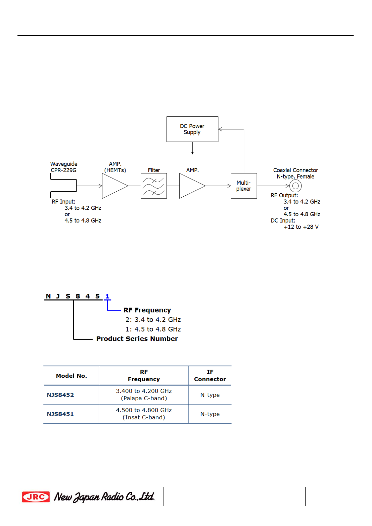
Scope
This LNA is intended for the satellite communication data downlink application in C-band. It is
combined a 3-stage HEMT amplifier.
The LNA receives an RF signal (C-band: 3.4 to 4.2 GHz, or 4.5 to 4.8 GHz) as input, amplifies and
outputs the RF signal. It is operated by +24 V DC power (range: +12 to +28 V) input.
The LNA comes in a single, weatherized housing rated for outdoor use, and has a CPR-229G waveguide
flange as RF input and an N-type female connector as RF output.
Fig.1 Functional Block Diagram
Series Model Number
Numbering System
Line-up
NJS8451 series
*Above specifications are subject to change without notice.
Reference No.:
DS-S8451
Rev.:
10E
Sheet:
4
1. Electrical Specifications
#
Items
Specifications
1.1.
Absolute Maximum Rating
[RF Input Power]
[Supply Voltage]
-10 dBm (@ CW), +10 dBm (@ Pulse)
+30 V DC
1.2.
Input RF Frequency Range
< Model No. NJS8451 >
4.5 to 4.8 GHz
< Model No. NJS8452 >
3.4 to 4.2 GHz
1.3.
Input RF Level
-135 to -65 dBm
1.4.
Noise Temperature @ +25 ºC
15 K typ., 30 K max.
1.5.
Conversion Gain @ +25 ºC
< Model No. NJS8451 >
55 dB min., 62 dB max.
< Model No. NJS8452 >
48 dB min., 55 dB max.
1.6.
Conversion Gain Ripple @ +25 ºC 2 dBp-p max.
at any 50 MHz segments.
1.7.
Conversion Gain Flatness over Frequency
@ +25 ºC
< Model No. NJS8451 >
3 dBp-p max. over 300 MHz BW
< Model No. NJS8452 >
5 dBp-p max. over 800 MHz BW
1.8.
Conversion Gain Variation over Temperature
5 dB max.
1.9.
Output Power @ 1dB G.C.P. (P1dB)
+7 dBm min.
1.10.
Output Intercept Point
+19 dBm min.
1.11.
Output V.S.W.R.
2 : 1 typ., 3 : 1 max.
1.12.
Power Requirement
[Input Port]
[Input Voltage]
[Current Drain]
RF Output Interface Connector
(Combine DC Power with Output RF Signal)
+12 to +28 VDC
125 mA typ., 160 mA max.
NJS8451 series
*Above specifications are subject to change without notice.
Reference No.:
DS-S8451
Rev.:
10E
Sheet:
5
2. Mechanical Specifications
#
Items
Specifications
2.1.
Input Waveguide Flange
Waveguide, CPR-229G (with Groove)
2.2.
RF Interface Connector
Coaxial Connector , N-type Female - 50 ohms
2.3.
Dimension & Housing
without Interface Connector
80.8 (L) x 99.6 (W) x 76 (H) mm
[3.18” (L) x 3.92” (W) x 2.99” (H) ]
2.4.
Weight 800 g
[1.76 lbs]
3. Environmental Specifications
#
Items
Specifications
3.1.
Temperature Range (Ambient)
[Operating]
[Storage]
-40 to +60 ºC
-40 to +80 ºC
3.2.
Humidity
0 to 100 % RH
3.3.
Altitude
15,000 feet (4,572 m)
3.4.
Vibration (Survival)
5 G [49.03 m/s
2
] (3 axis, 50 Hz)
3.5.
Shock (Survival)
15 G [147.1 m/s
2
] (3 axis)
3.6.
Waterproof / Dustproof
(IP Code Rating)
IP 67
3.7.
Regulations EU Directive (CE Marking)
EMC - 2014/30/EU
RoHS - 2011/65/EU + (EU)2015/863
Safety: EN60950-1
3.8.
MTBF
(by Method of Parts Count Reliability
Prediction)
150,000 hours and more at +60 ºC
as Design Condition
This manual suits for next models
2
Table of contents
Other New Japan Radio Power Supply manuals


Popular Power Supply manuals by other brands

Videx
Videx 520MR Installation instruction

Poppstar
Poppstar 1008821 Instructions for use

TDK-Lambda
TDK-Lambda LZS-A1000-3 Installation, operation and maintenance manual

TDK-Lambda
TDK-Lambda 500A instruction manual

Calira
Calira EVS 17/07-DS/IU operating instructions

Monacor
Monacor PS-12CCD instruction manual


