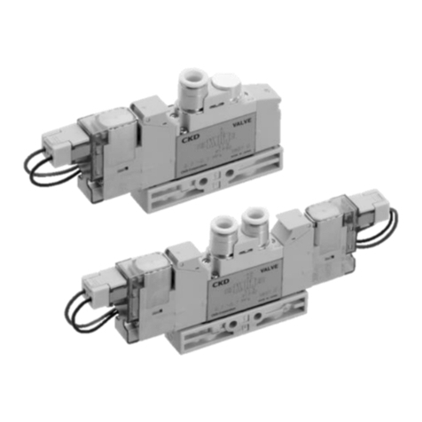
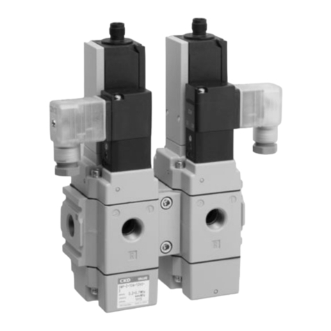
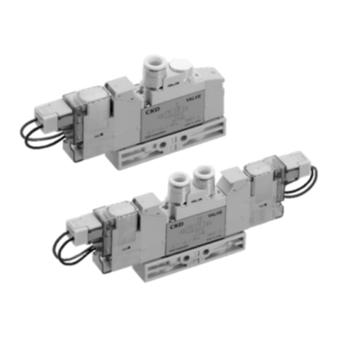
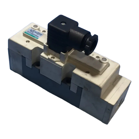
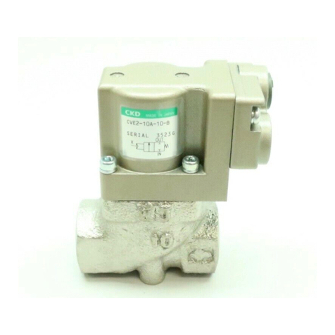
CKD 3KA1 User manual

SM−206792-A
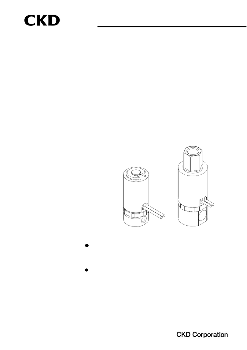
INSTRUCTION MANUAL
MASTER VALVE
3KA1, 4KA1, 4KB1
M3KA1,M4KA1,M4KB1
●Please read this instruction manual
carefully before using this product, par-
ticularly the section describing safety.
●Retain this instruction manual with the
product for further consultation whenever
necessary.
3rdEdition

[SM-206792-A/3] ―1
―
SAFETYPRECAUTIONS
WhendesigningandmanufacturingadeviceusingCKDproducts,themanufacturerisobli-
gatedtomanufactureasafeproductbyconfirmingsafetyofthesystemcomprisingthe
followingitems:
・Devicemechanism
・Pneumaticorwatercontrolcircuit
・Electriccontrolthatcontrolstheabove
Itisimportanttoselect,use,handle,andmaintaintheproductappropriatelytoensurethat
theCKDproductisusedsafely.
Observewarningsandprecautionstoensuredevicesafety.
Checkthatdevicesafetyisensured,andmanufactureasafedevice.
1.Thisproductisdesignedandmanufacturedasageneralindustrialmachinepart.Itmust
behandledbysomeonehavingsufficientknowledgeandexperience.
2.Usethisproductwithinitsspecifications.
This product cannot be used beyond its specifications. Additionally, the product must not be
modifiedormachined.
Thisproductisintendedforuseingeneralindustrialdevicesandparts.Usebeyondsuchconditions
is not considered. Consult with CKD for details when using the product beyond the unique
specificationrange,outdoors,orinthefollowingconditionsorenvironments.Inanycase,measures
forsafetyshallbeprovidedwhenthevavlemalfunctions.
①Useforspecialapplicationsrequiringsafetyincludingnuclearenergy,railroad,aviation,ship,vehicle,
medical equipment, equipment or applications coming into contact with beverage or food,
amusementequipment,emergencyshutoffcircuits,pressmachine,brakecircuits,orforsafeguard.
②Useforapplicationswherelifeorassetscouldbeadverselyaffected,andspecialsafetymeasures
arerequired.
3.Observecorporatestandardsandregulations,etc.,relatedtothesafetyofdevicedesign
andcontrol,etc.
ISO4414,JISB8370(pneumaticsystemrules)
JFPS2008(principlesforpneumaticcylinderselectionanduse)
Including High Pressure Gas Maintenance Law, Occupational Safety and Sanitation Laws, other
safetyrules,standardsandregulations,etc.
4.Donothandle,pipe,orremovedevicesbeforeconfirmingsafety.
①Inspectandservicethemachineanddevicesafterconfirmingsafetyoftheentiresystemrelatedto
thisproduct.
②Notethattheremaybehotorchargedsectionsevenafteroperationisstopped.
③Wheninspectingorservicingthedevice,turnofftheenergysource(airsupplyorwatersupply),and
turn off power to the facility. Release any compressed air from the system, and pay enough
attentiontopossiblewaterleakageandleakageofelectricity.
④When starting or restarting a machine or device that incorporates pneumatic components, make
surethatsystemsafety,suchaspop-outpreventionmeasures,issecured.
WARNING

[SM-206792-A/3]
−2−
5.Observewarningsandcautionsonthepagesbelowtopreventaccidents.
The safety cautions are ranked as "DANGER", "WARNING" and "CAUTION" in this
section.
FailuretopayattentiontoDANGERnoticesmaycauseasitu-
ation that results in a fatality or serious injury and that re-
quiresurgentaddressing
Failure topay attention toWARNING noticesmay result in a
fatalityorseriousinjury.
FailuretopayattentiontoCATIONnoticesmayresultininjury
ordamagetoequipmentorfacilities.
Notethatsome itemsdescribed as"CAUTION"may leadto seriousresultsdependingon the
situation.Inanycase,importantinformationthatmustbeobservedisexplained.
Precautionswithregardtoguarantee
Guaranteeperiod
Theguaranteeperiodofourproductshallbeone(1)yearafteritisdeliveredtotheplacespecifiedbythe
customer.
Guaranteecoverage
IfanyfailureforwhichCKDCORPORATIONisrecognizedtoberesponsibleoccurswithintheabovewar-
rantyperiod,asubstituteornecessaryreplacementpartsshallbeprovidedfreeofcharge,ortheproduct
shallberepairedfreeofchargeattheplantofCKDCORPORATION.
However,theguaranteeexcludesfollowingcases:
①Defectsresultingfromoperationunderconditionsbeyondthosestatedinthecatalogueorspecifications.
②Failureresultingfrommalfunctionoftheequipmentand/ormachinemanufacturedbyothercompanies.
③Failureresultingfromwronguseoftheproduct.
④FailureresultingfrommodificationorrepairingthatCKDCORPORATIONisnotinvolvedin.
⑤Failureresultingfromcausesthatcouldnotbeforeseenbythetechnologyavailableatthetimeofdeliv-
ery.
⑥FailureresultingfromdisasterthatCKDisnotresponsibleof.
Guaranteestatedherecoversonlythedeliveredproducts.Anyotherdamageresultingfromfailureofthede-
liveredproductsisnotcoveredbythisguarantee.
Confirmationofproductcompatibility
Ourcustomershallberesponsibleofconfirmingcompatibilityofourproductusedinourcustomer’ssystem,
machineryordevice.
!
WARNING:
!
CAUTION:
!
DENGER :

[SM-206792-A/3] ―3
―
UNPACKING (Section 3)
Bags containing master valves should be opened only
when you are ready to connect the valves to the pipes
immediatelyafterward.
Ifbagsareopenedbeforethevalvesarereadytobecon-
nectedtothepipes,theentryofforeignmatterfromthe
pipingportscouldcausethemastervalvestofailormal-
function.
INSTALLATION (Section 4)
Ifyouhavetousetheproductunderconditionsthatare
differentfromthespecifiedconditionsorifyouintendto
usetheproductforaspecialapplication,besuretocon-
sultusabouttheproductspecificationsbeforeusingthe
product.
ENVIRONMENT (Section 4.1)
a) Inadustyenvironment,foreignmattermayentereven
throughthemasterport.
The movement of the master valve causes a respiratory
actionatthemastervalve,whichmaycauseinhalationof
foreignmatterneartheexhaustport. Thispotentialsit-
uation would be worse if the exhaust port is facing up-
ward. Attachasilencertotheexhaustportorhavethe
exhaustportfacedownward.
b) Keep the master valve system dry. Take care to
avoiddirectcontactwithdrippingwaterorsplashesof
cuttingoil.
Ifthecylinderrodissplashedwithcuttingoil,theoilmay
penetrate through the cylinder into the secondary side
piping of the master valve. This must be prevented to
avoidmalfunctions. Consultusforpreventivemeasures.
c) Donotusethemastervalvesysteminanatmosphere
thatincludesacorrosivegasorsolventvapors.
Do not use the master valve system in an atmosphere
that includes a corrosive gas such as the sulfur dioxide
gasorinanatmospherethatincludessolventvapors.
d) Vibrationsandshocks
Do not subject the master valve system to vibrations
50m/s2orstrongerorshocks300m/s2orstronger.
!
CAUTION:
!
CAUTION:
!
CAUTION:

[SM-206792-A/3]
−4−
e) Avoidusingthemastervalvesysteminahumidenvi-
ronmentbecausethehumidityislikelytocausecon-
densationwithachangeinthetemperature.
f) Thepackingandgasketsmaydeterioratesoonerthan
usual if used in an atmosphere with a higher than
normaldensityofozone(forexample,theatmosphere
near a beach or in an area with frequent thunder-
storms).
Consultus forthepackingand gaskets tobe used inan
atmospherewithahigherozonedensity.
INSTALLATION (Section 4.2)
Wheninstallingamastervalveunit,neverattempttohold
itinpositionbymeansofthepipesconnectedtoit.
Mountthemastervalvebyapplyingthemountingscrews
and/ormountingplatetothemastervalve.
!
WARNING:
!
CAUTION:

[SM-206792-A/3] ―5
―
PIPING (Section 4.3)
a) Observe the recommended tightening torque when
connectingpipes.
Observing the recommended tightening torque prevents
airleakageanddamagetothescrewthreads. Toprevent
damagetothescrewthreads,firstuseyourhandtolightly
tightenthescrewandthenuseatooltotightenthescrew
totherecommendedtorque.
b) Makesurethat thepipeswill notbedisconnectedat
the joints by mechanical movements, vibrations or
tension.
If the exhaust piping of the pneumatic circuit is discon-
nected,theactuatorspeedcontrolisdisabled.
If the above happens to a chuck holding mechanism, the
chuck will open. The inadvertent opening of the chuck
maycauseaseriousaccident.
c) When supplying the compressed air for the first time
after completing the piping, be sure to check every
jointinthepipingforairleakage.
d) When supplying the compressed air for the first time
after completing the piping, increase the air pressure
graduallybut neverintroducea highly-pressurized air
suddenly.
A sudden introduction of a highly-pressurized air may
disconnectpipesatjointsand/orcausethetubestojump
around,anyofwhichmaycauseaninjury.
e) Donotdecreasetheinsidediameterofthepipingfrom
any of the master valve exhaustports to a diameter
lessthantheexhaustpipeconnectingportsize.
Normal operation of the actuator depends on the
smoothnessoftheexhaustflow.
f) Removalofforeignmatter
Rust and other foreign matter in the pneumatic circuit
may cause a malfunction or leakage fromthe valve seat.
Insert a filter (maximum allowable particle size 5μm or
less)immediatelyupstreamofthemastervalve.
g) Airsupply
Donotrestricttheflowofairthroughtheairsupplypip-
ing. Withamanifoldsystemwithmultiplestations,adrop
in the air supply pressure may cause trouble through a
delayintheoperationtiming.
!
CAUTION:

[SM-206792-A/3]
−6−
AIR QUALITY (Section 5.2)
a) Donotsupplyanythingotherthancompressedair.
b) Supply clean compressed air without any mixture of
corrosivegas.
a) Compressed air usually cont
ains a large amount of
drain, oxidized oil, tar, foreign matter, and rust from
thepiping. Filter outthose elementsinthesupplied
air because they may cause a malfunction and de-
crease service life. In addition, clean the exhaust
beforeitisreleasedtotheairtominimizepollution.
b) Once you have lubricated a pre-lubricated valve, the
valveisnolongercapableofrunningwithoutbeinglu-
bricated from the outside. Do not leave the valve
withoutlubricationbutkeepitlubricated.
c) Donot usespindleoilor machineoil. Theymayin-
duceexpansionoftherubberparts,whichmaycause
amalfunction.
PERIODIC INSPECTION (Section 6.1)
Beforeprovidingamaintenanceservice,cutandthesup-
plyofcompressedairandconfirmtheabsenceofresidu-
alpressure.
Theaboveisrequiredtoensuresafety.
Regularly perform the daily and periodic inspections to
correctlymaintainproductperformance.
If the productis not correctly maintained , product per-
formance may deteriorate dramatically, resulting in a
shorter service life, fractures of components, and mal-
functions.
DISASSEMBLING AND REASSEMBLING (Section 6.2)
Before disassembling and reassembling master valves,
readtheinstructionmanualcarefullyandunderstandthe
instructions.
A person who disassembles and reassembles a master
valve system needs to have a knowledge for safely per-
formingsuchoperationbasedontheunderstandingabout
themechanismsandoperatingprinciplesofmastervalves.
Personnel involved in this step must have passed the
PneumaticPressureSkillTestClass2orhigher.
!
WARNING:
!
CAUTION:
!
CAUTION:
!
WARNING:
!
WARNING:

―7
―
INDEX
3KA1,4KA1, 4KB1
M3KA1, M4KA1, M4KB1
MASTER VALVE
Manual No. SM-206792-A/3
1. PART NAME AND DESCRIPTION 8
2. INTERNATIONAL SYSTEM OF UNITS (SI) 9
3. UNPACKING 10
4. INSTALLATION
4.1 Environment 11
4.2 Installation 12
4.3 Piping 13
5. OPERATING RECOMMENDATION
5.1 Operation 17
5.2 Air Quality 20
6. MAINTENANCE
6.1 Periodic Inspection 22
6.2 Disassembling and Reassembling 23
7. TROUBLE SHOOTING 27
8. PRODUCT SPECIFICATIONS AND HOW TO ORDER
8.1 Product Specifications 28
8.2 How to Order 31
8.3 Consumable parts 37

[SM-206792-A/3]
−8−
PRODUCT
1
1. PARTNAMEANDDESCRIPTION
Direct piping unit Direct piping manifold
Subplate piping unit Subplate piping manifold
No. Part Name explanation
①Master valve unit There are direct pipng and subplaate piping
②Sub plate It is a block for the piping
③Piping Port Port pis the supply port;port R is the exhaust port ; port A and B is
the Output port
④Pilot air piping port It is pilot air,a supply port.(PA,PB)
⑤Mounting screw There are two every individual valve and it fixes the valve unit on
the Various base.

[SM-206792-A/3] ―9
―
SIUNIT
2
2. INTERNATIONALSYSTEMOFUNITS(SI)
In this manual, values are expressed using the International System of Units
(SI).
Use the table below to convert them into values expressed in conventional units.
Table of conversion between SI units and conventional units
(The values printed in Bolds fonts are values given in the International System of Units (SI)):
Force
N dyn kgf
1 1×1051.01972×10-1
1×10⁻⁵ 1 1.01972×10⁻⁶
9.80665 9.80665×1051
Stress
Pa or N/m2MPa or N/mm2kgf/mm2kgf/cm2
1 1×10⁻⁶ 1.01972×10⁻⁷ 1.01972×10⁻⁵
1×1061 1.01972×10⁻¹ 1.01972×10
9.80665×1069.80665 1 1×10²
9.80665×1049.80665×10-2 1×10⁻² 1
Note:1Pa=1N/m2, 1MPa=1N/mm2
Pressure
Pa kPa MPa bar kgf/cm2atm mmH2O mmHg or Torr
1 1×10⁻³ 1×10⁻⁶ 1×10⁻⁵ 1.01972×10⁻⁵ 9.86923×10⁻⁶ 1.01972×10⁻¹ 7.50062×10⁻³
1×1031 1×10⁻³ 1×10⁻² 1.01972×10⁻² 9.86923×10⁻³ 1.01972×1027.50062
1×1061×1031 1×10 1.01972×10 9.86923 1.01972×1057.50062×103
1×1051×1021×10-1 1 1.01972 9.86923×10⁻¹ 1.01972×1047.50062×102
9.80665×1049.80665×10 9.80665×10⁻² 9.80665×10⁻¹ 1 9.67841×10⁻¹ 1×1047.35559×102
1.01325×1051.01325×1021.01325×10-1 1.01325 1.01323 1 1.03323×1047.60000×102
9.80665 9.80665×10⁻³ 9.80665×10⁻⁶ 9.80665×10⁻⁵ 1×10⁻⁴ 9.67841×10⁻⁵ 1 7.35559×10⁻²
1.33322×1021.33322×10-1 1.33322×10⁻⁴ 1.33322×10⁻³ 1.35951×10⁻³ 1.31579×10⁻³ 1.35951×10 1
Note:1Pa=1N/m2
Example (converting a pressure value):
1kgf/cm2→0.0980665MPa 1MPa →1.01972×10kgf/cm2

[SM-206792-A/3]
−10−
UNPACKING
3
3. UNPACKING
Bags containing master valves should be opened only
when you are ready to connect the valves to the pipes
immediatelyafterward.
Ifbagsareopenedbeforethevalvesarereadytobecon-
nectedtothepipes,theentryofforeignmatterfromthe
pipingportscouldcausethemastervalvestofailormal-
function.
a) Check the model number imprinted on the product to make sure that the
product you received is exactly the product you ordered.
b) Check the exterior of the product for any damage.
c) Before using the product, read the supplied documentation.
!
CAUTION:

[SM-206792-A/3] ―11
―
INSTALLATION
4
4. INSTALLATION
Ifyouhavetousetheproductunderconditionsthatare
differentfromthespecifiedconditionsorifyouintendto
usetheproductforaspecialapplication,besuretocon-
sultusabouttheproductspecificationsbeforeusingthe
product.
4.1 Environment
a) Inadustyenvironment,foreignmattermayentereven
throughtheexhaustport.
Themovementoftheexhaustvalvecausesarespiratory
actionattheexhaustvalve,whichmaycauseinhalationof
foreignmatterneartheexhaustport. Thispotentialsit-
uation would be worse if the exhaust port is facing up-
ward. Attachasilencertotheexhaustportorhavethe
exhaustportfacedownward.
b) Keep the master valve system dry. Take care to
avoiddirectcontactwithdrippingwaterorsplashesof
cuttingoil.
Ifthecylinderrodissplashedwithcuttingoil,theoilmay
penetrate through the cylinder into the secondary side
piping of the master valve. This must be prevented to
avoidmalfunctions. Consultusforpreventivemeasures.
hot.
c) Donotusethemastervalvesysteminanatmosphere
thatincludesacorrosivegasorsolventvapors.
Do not use the master valve system in an atmosphere
that includes a corrosive gas such as the sulfur dioxide
gasorinanatmospherethatincludessolventvapors.
d) Vibrationsandshocks
Do not subject the master valve system to vibrations
50m/s2orstrongerorshocks300m/s2orstronger.
e) Avoidusingthemastervalvesysteminahumidenvi-
ronmentbecausethehumidityislikelytocausecon-
densationwithachangeinthetemperature.
!
CAUTION:
!
CAUTION:

[SM-206792-A/3]
−12−
INSTALLATION
4
2
-
φ
3.2
f) Thepackingandgasketsmaydeterioratesoonerthan
usual if used in an atmosphere with a higher than
normaldensityofozone(forexample,theatmosphere
near a beach or in an area with frequent thunder-
storms).
Consult us forthe packing and gaskets to be used in an
atmospherewithahigherozonedensity.
4.2 Installation
Wheninstallingamastervalveunit,neverattempttohold
itinpositionbymeansofthepipesconnectedtoit.
Mountthemastervalvebyapplyingthemountingscrews
and/ormountingplatetothemastervalve.
4.2.1 A work space for installation, removal, wiring, and piping opera-
tions should be provided around the installed master valve sys-
tem.
4.2.2 Direct mounting
1) Direct piping Type
Use two or four through holes
unit manifold
2) Sub plate piping Type
Use two mounting holes
unit manifold
!
WARNING:
!
CAUTION:
4-φ4.5
2-φ4.5
2-φ5.5

[SM-206792-A/3] ―13―
INSTALLAT
ION
4
4.3 Piping
a) Observe the recommended tightening torque when
connectingpipes.
Observing the recommended tightening torque prevents
airleakageanddamagetothescrewthreads. Toprevent
damagetothescrewthreads,firstuseyourhandtolightly
tightenthescrewandthenuseatooltotightenthescrew
totherecommendedtorque.
b) Make sure that the pipes will not be disconnected at
the joints by mechanical movements, vibrations or
tension.
If the exhaust piping of the pneumatic circuit is discon-
nected,theactuatorspeedcontrolisdisabled.
If the above happens to a chuck holding mechanism, the
chuck will open. The inadvertent opening of the chuck
maycauseaseriousaccident.
c) When supplying the compressed air for the first time
after completing the piping, be sure to check every
jointinthepipingforairleakage.
d) When supplying the compressed air for the first time
after completing the piping, increase the air pressure
gradually but never introducea highly-pressurized air
suddenly.
A sudden introduction of a highly-pressurized air may
disconnectpipesatjointsand/orcausethetubestojump
around,anyofwhichmaycauseaninjury.
e) Donotdecreasetheinsidediameterofthepipingfrom
any of the master valve exhaustports to a diameter
lessthantheexhaustpipeconnectingportsize.
Normal operation of the actuator depends on the
smoothnessoftheexhaustflow. Withamanifoldsystem,
arestrictiontotheexhaustflowmaypreventnormalop-
erationofothermastervalves.
f) Removalofforeignmatter
Rust and other foreign matter in the pneumatic circuit
may cause a malfunction or leakage from the valve seat.
Insert a filter (maximum allowable particle size 5μm or
less)immediatelyupstreamofthemastervalve.
g) Airsupply
Donotrestricttheflowofairthroughtheairsupplypip-
ing. Withamanifoldsystemwithmultiplestations,adrop
in the air supply pressure may cause trouble through a
delayintheoperationtiming
Approproate torque
Joint screw Approproate torque N・m
M5 1to 1.5
Rc1/8 3 to 5
!
CAUTION:

[SM-206792-A/3]
−14−
INSTALLATION
4
4.3.1 Sealant
Refrain applying sealant or seal tape approx.two pitches of thread from the
tip of pipe to avoid some of the sealing substances from falling into piping
system.
When winding the fluororesin seal tape on the screw part, wind the seal tape two
or three times where one or two screw threads remain at the top end of the screw,
and then push the tape by tip of the nail to make the tape tightly in contact with
the screw. When using the liquid sealant, apply a proper amount of sealant
where one or two screw threads remain at the top end of the screw.
At this time, do not apply the sealant to the female screw parts of the machine.
4.3.2 Flushing
Before connecting pipes, flush the interiors of the tubes, master valves, and
connected devices to remove foreign matter.
4.3.3 About M5 joint
M5 seal it with gasket (model:FGS). Don’t tight while increasing Pressure.
Consider a trouble of emergency, Design and enforce to be Possible to
remore and mount of a valve.
4.3.4 Blow circuit
Do not open the cylinder port circuit to the air because a drop in the air sup-
ply pressure may cause a malfunction.
4.3.5 Exhaust port
Minimize the restriction to the flow of the exhaust air because such re-
striction may cause a delay in the cylinder response. If such a delay hap-
pens, the speed needs to be adjusted between the cylinder and master valve.
(Right) (False) (Right) (False)
●SealTape ●Sealant(Pasteorliquid)

[SM-206792-A/3] ―15―
INSTALLATION
4
4.3.6 Pipe connections
(1) Tubes to be used
For use with master valves with one-touch joints, select tubes of the type
specified by us: Soft nylon tubes (F-1500 Series)
Urethane tubes (U-9500 Series)
(2) For installation at a site that has spatters in the air, select incombustible
tubes or metal pipes.
(3) For a piping used for both hydraulic and pneumatic controls, select a hydrau-
lic hose.
When combining a spiral tube with a standard one-touch joint, fix the tube
origin using a hose band. Otherwise the rotation of the tube will decrease the
efficiency of the clamping.
For use in a high-temperature atmosphere, select fastener joints instead of
one-touch joints.
(4) When selecting from tubes commercially available, carefully study the accu-
racy of the outside diameter as well as the wall thickness and the hardness.
The hardness of an urethane tube should be 93°C or more (as measured by
a rubber hardness meter).
With a tube that does not have a sufficient accuracy of the outside diameter
or the specified hardness, a decrease in the chucking force may cause dis-
connection or difficulty in inserting.
Tube dimensions
Outside diameter
mm
Inside diameter mm
Nylon Urethane
φ4 φ2.5 φ2
φ6 φ4 φ4
φ8 φ5.7 φ5
φ10 φ7.2 φ6.5
(5) Minimum bending radius of tubes
Observe the minimum bending radius of tubes. Neglecting the minimum
bending radius may cause disconnection or leaks.
Tube bore Minimum bending radius mm
Nylon Urethane
φ4 10 10
φ6 20 20
φ8 30 30
φ10 40 40
Outside diameter allowance
Soft or hard nylon ±0.1mm
Urethane φ4, φ6 +0.1mm
-0.15mm
Urethane φ8, φ10 +0.1mm
-0.2mm

[SM-206792-A/3]
−16−
INSTALLATION
4
(6) Cutting a tube
To cut a tube, use a tube cutter to cut the tube perpendicularly to the length
of the tube. Inserting an obliquely cut end of a tube may cause air leakage.
(7) Tube connections
Do not bend a tube immediately at where it is connected to the joint but lead
it out straight from the end of the joint for a length equal to or greater than
the outside diameter of the tube. The tension applied sideways through the
tube should not exceed 40N.
(8) Blank plug to be used
For use with a master valve with a one-touch joint, select the blank plug
specified by us: Blank plug GWP□-B Series

[SM-206792-A/3] ―17―
OPERATION
5
5. OPERATINGRECOMMENDATION
5.1 OPERATION
1)3KA series
3KA111
When PB no pressurization (See the right figure)
B → R2 (P port is closed.) B PB
When PB pressurization
P → B (R2 port is closed.)
P R2
3KA1111
When PB no pressurization (See the right figure)
P → A (R1 port is closed.)
When PB pressurization A PB
A → R1 (P port is closed.)
R1 P
3KA121
When PA pressurization (See the right figure)
B → R2
When PB pressurization
P → B PA B PB
Even if air is cut off after press-
urization,it maintaing the chan-
ging by the self
P R2

[SM-206792-A/3]
−18−
OPERATION
5
2)4KA series
4KA111
When PB no pressurization (See the right figure)
P → A
B → R2 (R1 port is closed.) A B PB
When PB pressurization
P → B
A → R1 (R2 port is closed.)
R1 P R2
4KA121
When PA pressurization (See the right figure)
P → A
B → R2 (R1 port is closed.) PA A B PB
When PB pressurization
P → B
A → R1 (R2 port is closed.)
Even if air is cut off after pressuri-
zation,it maintaing the changing by
the self
R1 P R2
4KA131, 4KA141, 4KA151
When 4KA131 is PA,PB no pressurization (See the right figure)
P・A・B・R1・R2 are closed.
When 4KA141 is PA,PB no pressurization PA A B PB
P (Closed.)
A → R1
B → R2
When 4KA151 is PA,PB no pre-
ssurization
P → A・B
R1・R2 (Closed) R1 P R2
Refer to the function of 4KA121 concerning the case of PA or PB which is
pressurization

[SM-206792-A/3] ―19―
OPERATION
5
2) 4KBseries
4KB111
When PB no pressurization (See the right figure)
P → A PB
B → R
When PB pressurization
P → B
A → R
A P B R
4KB121
When PA pressurization (See the right figure)
P → A
B → R PA PB
When PB pressurization
P → B
A → R
Even if air is cut off after press-
urization,it maintaing the chan-
ging by the self
A P B R
4KB131, 4KB141, 4KB151
When 4KA131 is PA,PB no pressurization (See the right figure)
P・A・B・R are closed.
When 4KA141 is PA,PB no pressurization
P (Closed.)
A・B → R PA PB
When 4KA151 is PA,PB no
pressurization
P → A・B
R (Closed.)
Refer to the function of 4KB121
concerning the caseof PA or PB
which is pressurization A P B R
Other manuals for 3KA1
1
This manual suits for next models
5
Table of contents
Other CKD Control Unit manuals
Popular Control Unit manuals by other brands

Siemens
Siemens S5-155U System manual

Mini-Circuits
Mini-Circuits RUDAT Series user guide

Roger
Roger H70/103AC Installer's instructions

Emerson
Emerson Sempell S Series operating instructions

Inge
Inge dizzer L Series Assembly instructions

Lansdale
Lansdale LPBT Series Installation, maintenance & operating instructions