manuals.online logo
Brands
  1. Home
  2. •
  3. Brands
  4. •
  5. Niigata seiki
  6. •
  7. Measuring Instrument
  8. •
  9. Niigata seiki CDI-50 User manual

Niigata seiki CDI-50 User manual

This manual suits for next models

2

Other Niigata seiki Measuring Instrument manuals

Niigata seiki N-5AS User manual

Niigata seiki

Niigata seiki N-5AS User manual

Niigata seiki GDCS-150NP User manual

Niigata seiki

Niigata seiki GDCS-150NP User manual

Niigata seiki WCDI-6 User manual

Niigata seiki

Niigata seiki WCDI-6 User manual

Niigata seiki D-HL Series User manual

Niigata seiki

Niigata seiki D-HL Series User manual

Niigata seiki DI-1058 User manual

Niigata seiki

Niigata seiki DI-1058 User manual

Niigata seiki SIC EMH-25F User manual

Niigata seiki

Niigata seiki SIC EMH-25F User manual

Niigata seiki ALD Series User manual

Niigata seiki

Niigata seiki ALD Series User manual

Niigata seiki GDCS-100WR User manual

Niigata seiki

Niigata seiki GDCS-100WR User manual

Niigata seiki DT Series User manual

Niigata seiki

Niigata seiki DT Series User manual

Niigata seiki DTW-DL01 User manual

Niigata seiki

Niigata seiki DTW-DL01 User manual

Niigata seiki LEVELNIC DL-S3 DL-BW User manual

Niigata seiki

Niigata seiki LEVELNIC DL-S3 DL-BW User manual

Niigata seiki LSL-26 User manual

Niigata seiki

Niigata seiki LSL-26 User manual

Niigata seiki DHG-35M User manual

Niigata seiki

Niigata seiki DHG-35M User manual

Niigata seiki GDCS-150DR User manual

Niigata seiki

Niigata seiki GDCS-150DR User manual

Niigata seiki TVC-15S User manual

Niigata seiki

Niigata seiki TVC-15S User manual

Niigata seiki SCDI S Series User manual

Niigata seiki

Niigata seiki SCDI S Series User manual

Niigata seiki GHS Series User manual

Niigata seiki

Niigata seiki GHS Series User manual

Niigata seiki BEVEL BOX User manual

Niigata seiki

Niigata seiki BEVEL BOX User manual

Niigata seiki PROFESSIONAL DI-10KD User manual

Niigata seiki

Niigata seiki PROFESSIONAL DI-10KD User manual

Niigata seiki QEM394 Series User manual

Niigata seiki

Niigata seiki QEM394 Series User manual

Niigata seiki DTW-DG02 User manual

Niigata seiki

Niigata seiki DTW-DG02 User manual

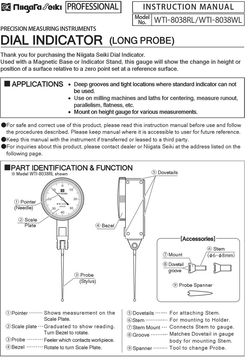
Niigata seiki WTI-8038RL User manual

Niigata seiki

Niigata seiki WTI-8038RL User manual

Niigata seiki TVC-60 User manual

Niigata seiki

Niigata seiki TVC-60 User manual

Niigata seiki CJU BKD Series User manual

Niigata seiki

Niigata seiki CJU BKD Series User manual

Popular Measuring Instrument manuals by other brands

Powerfix Profi 278296 Operation and safety notes

Powerfix Profi

Powerfix Profi 278296 Operation and safety notes

Test Equipment Depot GVT-427B user manual

Test Equipment Depot

Test Equipment Depot GVT-427B user manual

Fieldpiece ACH Operator's manual

Fieldpiece

Fieldpiece ACH Operator's manual

FLYSURFER VIRON3 user manual

FLYSURFER

FLYSURFER VIRON3 user manual

GMW TG uni 1 operating manual

GMW

GMW TG uni 1 operating manual

Downeaster Wind & Weather Medallion Series instruction manual

Downeaster

Downeaster Wind & Weather Medallion Series instruction manual

Hanna Instruments HI96725C instruction manual

Hanna Instruments

Hanna Instruments HI96725C instruction manual

Nokeval KMR260 quick guide

Nokeval

Nokeval KMR260 quick guide

HOKUYO AUTOMATIC UBG-05LN instruction manual

HOKUYO AUTOMATIC

HOKUYO AUTOMATIC UBG-05LN instruction manual

Fluke 96000 Series Operator's manual

Fluke

Fluke 96000 Series Operator's manual

Test Products International SP565 user manual

Test Products International

Test Products International SP565 user manual

General Sleep Zmachine Insight+ DT-200 Service manual

General Sleep

General Sleep Zmachine Insight+ DT-200 Service manual

Sensa Core Lacto Spark user manual

Sensa Core

Sensa Core Lacto Spark user manual

VOLTCRAFT UTS-1980 operating instructions

VOLTCRAFT

VOLTCRAFT UTS-1980 operating instructions

EBCHQ 94915 Operation manual

EBCHQ

EBCHQ 94915 Operation manual

Balluff BIP LD2-T017-01-EP-S4 Series user guide

Balluff

Balluff BIP LD2-T017-01-EP-S4 Series user guide

Pulsar IMP Lite Series instruction manual

Pulsar

Pulsar IMP Lite Series instruction manual

ETCR 6800 user manual

ETCR

ETCR 6800 user manual

manuals.online logo
manuals.online logoBrands
  • About & Mission
  • Contact us
  • Privacy Policy
  • Terms and Conditions

Copyright 2025 Manuals.Online. All Rights Reserved.

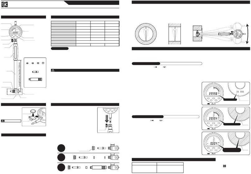
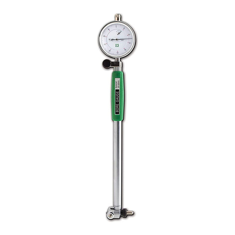
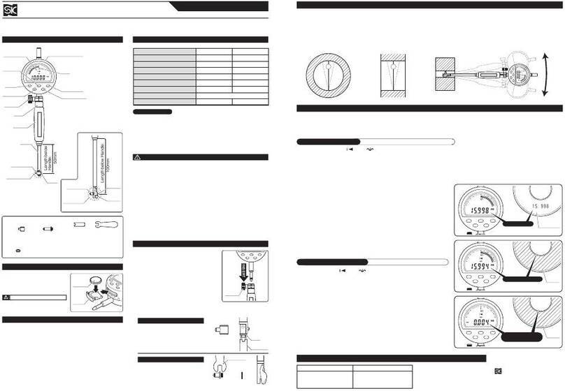
Thank you for purchasing the DIAL Bore Gauge.
Please read this manual thoroughly before use for proper operation.
Model No. : CDI-50 / CDI-100 / CDI-160 <combined>
DIAL BORE GAUGE
Revolution Counter
Model No. CDI-50
35〜50
15
5
1.2
0.5, 1, 2, 3 mm (One each)
1.05
CDI-100 CDI-160
50〜100
0.01
18
6
3
1.6
1.1
50〜160
18
6
1.6
1.15
Measuring Range
Graduation
Wide Range Accuracy
Adjacent Error
Repeat Accuracy
Extension Washer
Weight
Bezel
Extension Washer
Protective Cover
Extension Rod
55mm Sub Rod
(CDI-160 only)
Extension Rods:
CDI-50・・・・・35, 40, 45, 50mm (4 pieces)
CDI-100・・・50, 55, 60, 65, 70, 75, 80, 85, 90, 95, 100mm (11 pieces)
CDI-160・・・
50, 55, 60, 65, 70, 75, 80, 85, 90, 95, 100, 105mm
(12 pieces)
     +Sub Rod 55mm (1 piece)
Grip
Dial Indicator
Pointer
(0.01mm)
(1mm)
Spacer
Indicator
Face
Extension Rod
Rod Mounting
Nut
Rod Mounting Nut
Shaft
Probe Tip
Length below grip - 150mm
Guide
Measurement Head
Clamp Screw
Clamp
Screw
*
:Including supplied Dial Indicator.
*
*
*
This is a precision instrument, use care not to drop or mishandle.
Please do not disassemble or modify.
Keep instrument away from water and oil.
Use only with provided Extension Rod, Washers, and Sub Rod.
Keep instrument away from direct sunlight or high temperatures
such as in a car, or near a stove or heat source.
After use, remove dust and cutting chips, and apply rust
preventative oil to Extension Rod and Washers. When not in use
store in original storage case.
This product is for measuring inside diameter. Use only as
directed. Improper use may cause accident or injury.
②Loosen the Clamp Screw and insert the Dial
Indicator until the Pointer rotates 1/10 turn or more.
Secure by tightening the Clamp Screw.
①Remove the protective cover by unscrewing the two
screws that hold the cover in place.
※To reattach the protective cover, please refer to the section:
“Attaching the Protective Cover”
③Chose combination of Rod, Washer, and Sub Rod (CDI-160D only)
applicable for desired measurement range.
 Remove the Rod Mounting Nut and install the selected Rod,
Washers and Sub Rod, then replace Mounting Nut to secure to body.
※When selecting washers, use combination with fewest washers.
●
●
●
●
●
●
●
0.5mm 1mm 2mm 3mm
1/10 rotation
or more Extension Rod
60mm
Extension
Rod
60mm
Extension
Rod
60mm
Extension
Washer
2mm
Extension
Washer
0.5mm
+ +
Extension
Washer
3mm
Sub Rod
55mm
+ +
Example: For 60mm Measurement
Example: For 62.5mm Measurement
Example: For 118mm Measurement
■PART IDENTIFICATION
■ASSEMBLY
■SPECIFICATIONS
■NOTICE
Insert
INSTRUCTION MANUAL
(mm)
(mm)
(μm)
(μm)
(μm)
(mm)
(kg)
Single Probe Measuring Range
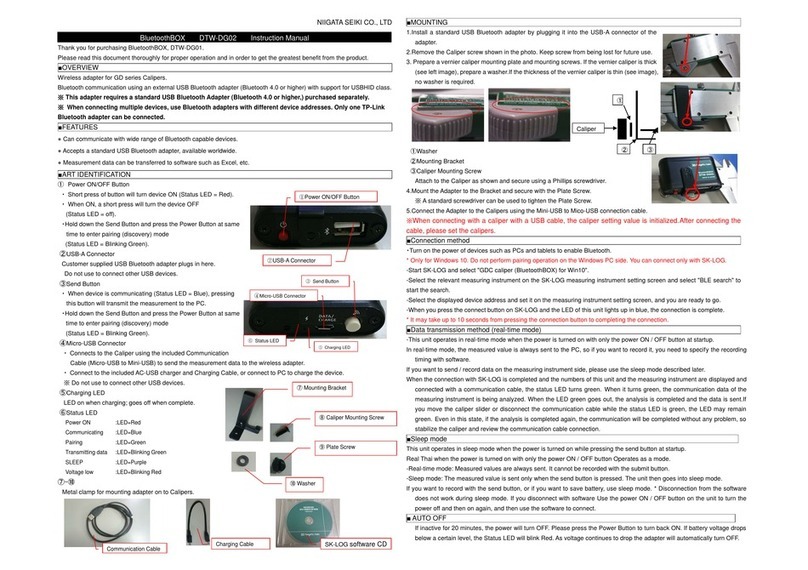
Bezel
Protective
Cover
Indicator
Screws
Spacer
Clamp Screw
MEASUREMENT
①Prepare a ring gauge to use as a reference standard for
setting the zero-point. Insert the Measurement Head
into the ring gauge.
②In cross section perpendicular to the axis of the ring
gauge, position the gauge along diameter ⓐ(Figure: 1).
This is the maximum distance, and at this point the Dial
Indicator will read the minimum value. The Gauge Head
will automatically sit in this position when inserted.
③In cross section parallel to the axis of the ring gauge
through diameter ⓐ, position the indicator to minimize
the distance ⓑ(Figure: 2). In this position the Dial
Indicator will read the maximum value. This position
must be manually achieved by moving the indicator and
noting the position where the Pointer shows the
maximum value. (Figure: 3)
④The reading obtained at step ③is the zero-point.
Rotate the bezel of the gauge until the Pointer is at the
zero point of the Indicator Face. (Figure: 4)
ZERO POINT ADJUSTMENT
※Before use, please make sure the Measurement Head is
secure. Tighten as necessary.
To use the Protective Cover, please attach using the following procedure.
①Loosen the Clamp Screw and remove Clamp and Spacer from shaft. (Figure: 5)
②Follow the “Assembly”procedure to mount the Indicator and secure with the Clamp.
③Mount the Protective Cover to the Indicator and attach with the 2 mounting screws.
(Figure: 6)
●If Gauge does not operate properly, or if you have any questions, please contact
distributor or place of purchase.
●Please note, manufacturer is unable to respond to inquires or provide service directly.
Please contact distributor or place of purchase.
Insert the Measurement Head of the Bore Gauge into the
object to be measured. As in step ③of “Zero-Point
Adjustment”above, pivot the gauge while checking the
pointer to determine the diameter ⓑwhere the indicator
will show the maximum value to determine the
measurement reading.
■OPERATION
■ATTACHING THE PROTECTIVE COVER
■REPAIRS AND SERVICE
Install
RemoveRemove
Rotate
Set to Zero
(Figure: 1)
(Figure: 3)
(Figure: 4)
(Figure: 5) (Figure: 6)
(Figure: 2)
Niigata seiki Co., Ltd.
6-15-22, Tsukanome, Sanjo, Niigata, Japan, 955-0055
Tel. : +81-256-31-5660 Fax. : +81-256-39-7730
MAIL:[email protected]
URL
http://www.niigataseiki.co.jp
I250-K 1508
ⓐⓑ