Newcon Optik NVS 7-3XT User manual

Operation Manual
NVS 7 Series
NIGHT VISION BINOCULARS/GOGGLES
NVS 7-3XT, NVS 7-3AG, NVS 7-3AGBW, NVS 7-3/4xXT, NVS 7-3/5xXT, NVS 7-3/8xXT
NSN: 5855-20-000-8284
105 Sparks Ave., Toronto, ON, M2H 2S5, Canada

ii

iii
IMPORTANT INFORMATION
Read prior to activation.
You have purchased a sophisticated electronic device. To
operate it properly, please read this manual carefully.
Ignoring the operation procedures described in this manual
will void your warranty.
NEVER disassemble the Unit. This device contains a source
of high voltage, which may be hazardous to your health.
NEVER open the objective lens of an active Unit in bright
light, including daylight. In the daytime the objective lens
must be covered by the lens cap provided. The tiny hole in
the cap provides enough light for daytime testing.
NEVER aim an active Unit at intense light sources, such as
lights, headlamps, campfires, the moon, etc.
NEVER reverse the polarity of a battery.
NEVER connect the Unit to any external power supplies.
ALWAYS remove battery when not in use for extended
period.
ALWAYS keep the objective lenses covered when not in use.
ALWAYS store the device in a warm dry place.

iv
Precautions
All NVS 7 series devices are sophisticated precise electro-optical
instruments. It should be handled with due care:
Each Unit contains fragile components. Avoid hard impacts,
dust, moisture and abrupt changes of temperature.
Do not touch the optical surfaces other than for cleaning with
an appropriate lens cleaning kit. Doing so may damage the
anti-reflective coating.
Clean optical surfaces with professional lens cleaning
supplies.
Use only a soft clean cloth to clean the exterior of the device.
Keep the device away from sources of heat, such as heating
appliances, sunlight or central heating.
Switch off the Unit and remove the battery during extended
periods of non-operation.
Do not apply excessive force or pressure to the lens assembly,
movable parts or threaded connections.
Small dark and/or light spots may be seen in the field of view
due to considerable optical magnification of the eyepiece.
This does not affect the operational capabilities of the device.

1
CONTENTS
NVS 7 Series Models
1.OVERVIEW .............................................................. 3
2.DELIVERY SET........................................................ 5
Standard delivery set........................................................ 5
Optional accessories ........................................................ 5
3.SPECIFICATIONS.................................................... 6
4.UNIT DESIGN .......................................................... 8
5.OPERATION INSTRUCTIONS ............................... 9
Installing battery .............................................................. 9
Activating the Unit .......................................................... 9
Switching the Unit off ................................................... 10
Operating at night .......................................................... 10
Focusing the Unit........................................................... 11
Using Unit with headgear .............................................. 11
Interpupillary distance ................................................... 11
Installation of interchangeable lenses ............................ 11
Auto shut OFF in flip up position (AUTO switch
position)......................................................................... 12
Auto shut OFF at bright light......................................... 13
Auto-gating system........................................................ 13
Integrated protection circuits ......................................... 14
Using NVS H mount (helmet mount) ............................ 16

2
Defogging options ......................................................... 17
6.TROUBLESHOOTING........................................... 19
No green (or black and white) image visible ................. 19
Image is unclear............................................................. 19
Image flashes ................................................................. 19
Condensation accumulates on Unit................................ 19
Visibility decreased or disappeared ............................... 19
7.WARRANTY........................................................... 20
8.CUSTOMER SUPPORT ......................................... 21
9.ACCEPTANCE CERTIFICATE ............................. 22

3
1. OVERVIEW
Your NVS 7 series device (the “Unit”) is an optoelectronic
goggle intended for observation of objects and orientation at
night or under dark conditions. The Unit is equipped with an
advanced Generation 3 (“Gen 3”) image intensifier tube (“IIT”),
which amplifies low light, such as moonlight, starlight or man-
made light and converts it into a clear visible image.
3x, 4x, 5x and 8x add-on lenses can be attached to the Unit to
increase system magnification for use as binoculars.
In its 1x configuration, the Unit can be mounted on a combat
helmet or head harness.
Some typical activities where NVS 7 series devices can be
useful:
Law enforcement
Wildlife observation
Security
Search and rescue
Hunting (where permitted by law)
Features
Built-in infrared illuminator allows observation in total
darkness (i.e. cave or dark room);
Helmet mount (optional) allows for effective combat
operations;
Flip-up mechanism allows for unobstructed vision when
the Unit is mounted on headgear or helmet;

4
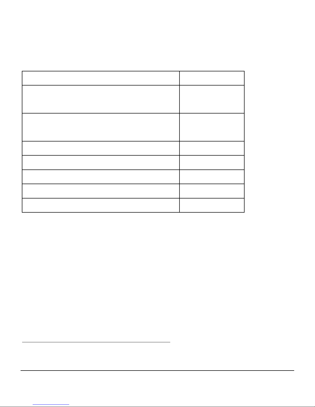
Waterproof design (standard 1 meter immersion for 30
minutes, other waterproofing options available);
Soft rubber eyecup makes viewing comfortable.
Please read all the instructions carefully prior to using the Unit.
Manufacturer reserves the right to introduce minor design
changes without notice.
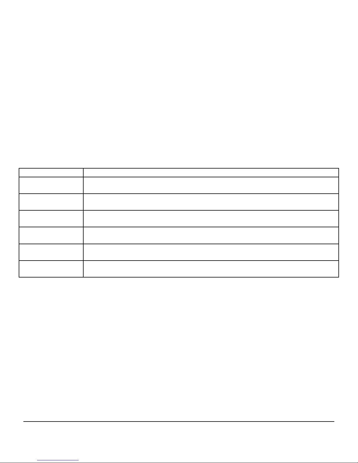
NVS 7 Series Models
Model Brief Description
NVS 7-3XT Military specification night vision goggles with 1x magnification, Gen 3 IIT,
helmet/head mountable, green image.
NVS 7-3AG Military specification night vision goggles with 1x magnification, Gen 3 IIT, auto-
gated power supply helmet/head mountable, green image.
NVS 7-3AGBW Military specification night vision goggles with 1x magnification, Gen 3 IIT, auto-
gated power supply helmet/head mountable, black and white image.
NVS 7-3/4xXT Military specification night vision binoculars with 4x magnification, Gen 3 IIT,
green image (available in AG and AGBW variants).
NVS 7-3/5xXT Military specification night vision binoculars with 5x magnification, Gen 3 IIT,
green image (available in AG and AGBW variants).
NVS 7-3/8xXT Military specification night vision binoculars with 8x magnification, Gen 3 IIT,
green image (available in AG and AGBW variants).

5
2. DELIVERY SET
Standard delivery set
QUANTITY
In goggle configuration1:
NVS 7 Unit with 1x lens and headgear
1
In binocular configuration2:
NVS 7 Unit with 4x, 5x or 8x lens
1
Objective lens cap 1
Neck/shoulder strap 1
Soft carrying case 1
Operation manual 1
AA batteries 2
Optional accessories
3x Afocal Lens
Lens Cleaning Kit
Demist Shield/Sacrificial Window
Hard case
NVS H Mount (helmet mount)
NVS Coupler
Exact Delivery Set is subject to specific contract terms.
1NVS 7-3XT, NVS 7-3AG, NVS 7-3AGBW
2NVS 7-3/4xXT, NVS 7-3/5xXT, NVS 7-3/8xXT

6
3. SPECIFICATIONS
Model 3XT 3AG 3AGBW
IIT Generation Gen 3
Photocathode Material Gallium Arsenide (GaAs)
Image Colour Green Black & White
Photocathode Diameter 17.5mm
Minimum Photocathode
Sensitivity
1800 µA/lm3
190 mA/W4
Luminous Gain 40,000 – 70,000 fL/fc5
10,000 – 20,000 fL/fc6
Auto-gating X
Minimum Resolution764 lp/mm
Minimum Signal to Noise824
Bright Source Protection
Automatic Brightness Control
Apparent Field of View 40º
Eye Relief 25 mm
1x Objective Focal Length / F
Number 27.5 mm / F1.2
4x , 8x Objective Focal Length,
mm / F Number 100 / F1.5, 216.4 / F2.0
Interpupillary Distance 57-73 mm
Focus Range (1x) 0.25 m to infinity
Dioptric Correction ±5
Battery Type 2x AA
3@2856°K
4@830nm
5@2x10⁻⁶ fc
6@2x10⁻⁴ fc
7,8Higher minimum available as per contract

7
Battery Life Over 80 hours without IR; over 30 hours with IR
Low Battery Indicator
IR ON Indicator
Waterproof MIL-STD-810G
Maximum Current Consumption 25mA
Voltage 2.8
0.8 V
Dimensions 1x: 150x120x55mm; 4x: 165x120x70mm
5x: 230x136x82mm; 5x: 240x130x130mm
Weight 1x: 480g; 4x: 690g
5x: 800g; 8x:1,470g
Operating Temperature -50°C to +55°C
MTBF 10,000 hours
Modulation Transfer Function
@2.5 lp/mm 92%
@7.5 lp/mm 80%
@15.0 lp/mm 61%
@25.0 lp/mm 38%
Black Spots Allowed per Zone
Spot Size
(inches) Zone 1 Zone 2 Zone 3
0.012 ~
0.015 0 0 0
0.009 ~
0.012 0 0 0
0.006 ~
0.009 0 1 1
0.003 ~
0.006 0 2 2
As the design of NVS 7 series devices is being continuously improved, delivered
specifications may be superior to those above. Where a discrepancy exists
between the specifications above and the specifications in your contract/purchase
order, the contract/purchase order takes precedence.

8
4. UNIT DESIGN
FIGURE 1
1. AUTO/OFF/ON/IR switch
2. Mounting socket
3. Diopter adjustment ring
4. Eyepieces
5. Battery compartment cover
6. Objective lens cap
7. Objective lens
8. Tightening knob
9. Release button
10. IR illuminator
FIGURE 2
1
8
7
9
3
4
2
5
6
10

9
FIGURE 3
Low battery indicator
5. OPERATION INSTRUCTIONS
Installing battery
Unpack the device. Unit is supplied with battery not installed.
Prior to installing the battery, make sure the
AUTO/OFF/ON/IR switch (1, Fig.1) is in the OFF position
and the objective lens cap (6, Fig, 1) is on.
Unscrew the battery compartment cover (5, Fig.1), and install 2
fresh AA batteries. Observe the correct polarity indicated on the
housing. Replace the battery compartment cover.
Activating the Unit
In daylight ensure the objective lens cap is in place prior to
activating the Unit.
To check if the Unit is operational switch it ON by rotating the
AUTO/OFF/ON/IR switch clockwise
while looking through the eyepieces (4,
Fig.1). You should see either a green or
black and white image (depending on
the model you have purchased). If the
screen is not lit ensure the batteries
installed are charged and the polarity
is correct.
When the Unit is ON you may see a red
LED indicator in the field of view (Fig.

10
3). When this indicator is blinking this indicates low battery
power. For uninterrupted operation keep fresh batteries ready and
replace them on time. If this indicator is displayed as a solid red
light, this indicates that the IR illuminator is activated. This
warning is intended to prevent the user from unintentionally
giving away their position.
In the daytime with the objective lens cap on, it is normal to
observe a ‘fuzzy’ image. Switching on the Unit in the daytime is
intended for testing purposes only. During night use, the
objective lens cap should be removed and the ‘fuzzy’ image
should no longer be observed.
Switching the Unit off
After you have finished using the Unit, turn it off by rotating the
On/Off/IR switch to the ‘OFF’ position. Replace the objective
lens cap. If storing the unit for an extended period, remove
batteries. Place Unit in appropriate storage container.
Operating at night
Remove the objective lens cover. Turn on the device. If
lighting is insufficient, activate the IR illuminator by
further rotating the AUTO/OFF/ON/IR switch. The LED
indicator (Fig. 3) should activate. The IR illuminator is
intended to aid in observing relatively close objects and is
not intended for long range use.
Caution: The IR illuminator is visible to anybody using a
night vision device.

11
Focusing the Unit
Turn on the Unit. Direct the device at an object placed within 8-
15 m from the viewer. While looking through the Unit at the
object, first rotate the diopter adjustment ring on each eyepiece
(3, Fig. 1). Once focus is nearly achieved, rotate the objective
lens (7, Fig. 1) to achieve final focus.
Using Unit with headgear
Prior to using the Unit with headgear (headgear not
provided with 4x, 5x and 8x variants) adjust all the straps
to accommodate your head size.
When wearing the Unit the eye-relief (distance between
your eyes and the eyepieces) should be 15-22 mm. In
order to achieve this, loosen the tightening knob (8, Fig.1)
and set a comfortable distance between the eyes and the
eyepieces; then tighten the tightening knob.
Interpupillary distance
The Unit is designed to accommodate interpupillary distance of
57-73mm without any additional adjustment and should be
comfortable for 99% of adults.
Installation of interchangeable lenses
Do not apply excessive force when changing lenses.
The following procedure is identical for 1x, 4x, 5x or 8x lenses.
1. Make sure the Unit is off.
2. Remove the objective lens cap.

12
3. To detach the current lens: hold the lens by its base and
rotate it counter-clockwise. Once the lens has been
removed, store it in a safe, clean space.
4. To attach desired lens: rotate it clockwise along the
threading until snug—do not overtighten.
The threads are very fine (to prevent humidity penetration) and
can be damaged easily. Do not apply force when rotating the
lens. If the desired lens does not rotate smoothly along the
threading, make sure that the threads are aligned.
The Unit is ready for operation immediately after the lens
change. During operation in brightly lit spaces, ensure the
objective lens cap is in place.
Auto shut OFF in flip up position (AUTO switch
position)
This unit is equipped with an orientation sensor, which
recognizes whether the device is in horizontal or vertical
orientation. The function works only in the main switch position
called “AUTO”. Upon changing the device orientation to vertical
(angle approximately 45 degrees and higher), the device will
automatically switch off to preserve the battery and image
intensifier tube lifetime as well as limit the illumination of the
operators face. Once unit is returned to horizontal orientation or
to an angle less than 45 degrees, the device will automatically
continue normal operation.

13
Auto shut OFF at bright light
Each unit has a built-in high light sensor located near the IR
illuminator (10, Fig. 1). This sensor shuts the goggles off after
approximately 40 seconds of exposure to light exceeding 40 lux.
To reset the device after auto shut off, switch it off and then back
on as described in Section 5.
The auto shut off feature does not mean that the unit will react to
occasional flashes or bright light spot sources. It protects the
device against excessive permanent light exposure in order to
avoid permanent damage of the IIT.
Notes:
Auto-gated (AG, AGBW) devices, also have this function. The
AG and AGBW devices require protection of the IIT against
prolonged exposure to any high light conditions, because such
conditions are going to substantially reduce life time of the auto-
gated IIT.
This function is active even if the device is used with the
protective cap on the objective lens.
Auto-gating system
The NVS 7-3AG and NVS 7-3AGBW variants contain, in
addition to the systems described above, an auto-gated power
supply. This system automatically controls the power supplied to

14
the IIT in changing lighting conditions. Auto-gating turns off the
photocathode voltage for brief periods of time, but the effect is
not visible to the human eye. This serves not only to protect the
IIT from exposure to bright lighting sources, but also to
automatically provide the user with the optimal image regardless
of prevailing light condition.
Note: the auto-gated variants of the device are not intended to be
continuously used under bright light conditions (above 10-1 lux).
The main purpose of the auto-gating function is to eliminate the
negative influence of rapidly changing lighting conditions and to
improve overall image quality at higher level of input light and
during flashing light.
Integrated protection circuits
To automatically control the output brightness of the tube under
changing input light conditions, the device is equipped with
protection circuits called automatic brightness control (ABC) and
bright source protection (BSP).
The main purpose of these functions is to protect both the image
tube from highlight exposure and the user’s eyes from excessive
brightness
The ABC automatically reduces voltage to the microchannel
plate to keep the image intensifier output brightness within
optimal limits and to protect the tube. This can be seen during
rapid changes from low-light to high-light conditions when the
image gets brighter and then quickly returns to a consistent level.

15
This function is still active in the device equipped with an auto-
gated IIT.
The BSP reduces voltage to the photocathode rather than the
microchannel plate. The BSP protects the image intensifier tube
from damage and enhances its lifetime. This function works in
bright light conditions that create input light with intensity higher
than 0.1lux.

16
FIGURE 7
1. Locking screw
2. Flip-up button
3. Flip-up adjusting screws
4. Mount binding screw
1 2 3
4
Using NVS H mount (helmet mount)
FIGURE 4
The Unit can be equipped with an optional NVS H Mount
which fits a variety of existing helmet models.
The Unit is fixed to the mount via a locking screw (1, Fig.
4). To adjust the position of the Unit to your eye level, use
the mount binding screw (4, Fig. 4). To adjust the eye
relief first loosen locking screw and set a comfortable
distance between the eyes and the eyepiece; then tighten
the locking screw.
The Unit can be fixed in three predetermined positions: vertical,
horizontal, and 15-20° above horizontal. Although the relative
angles between these positions cannot be changed, the starting
This manual suits for next models
6
Table of contents
Other Newcon Optik Accessories manuals