NewLine Ravello User manual
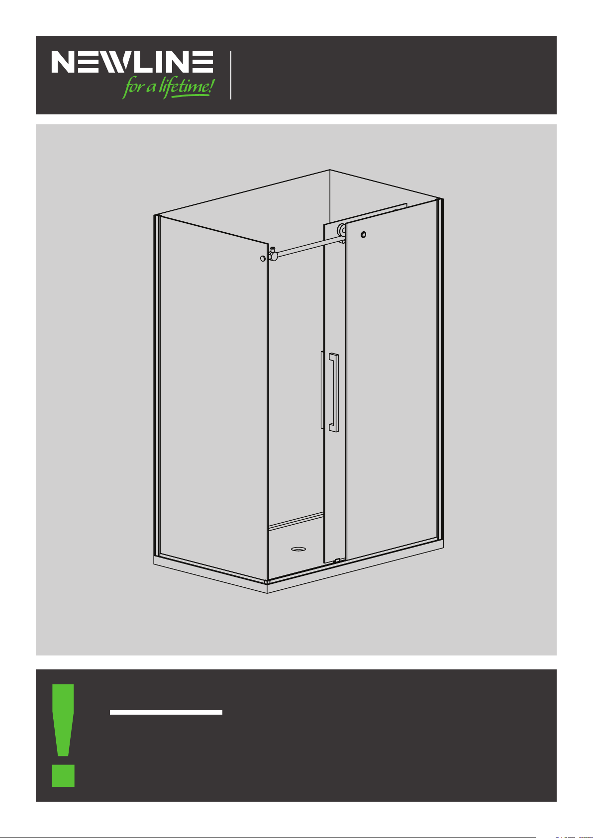
Ravello 2-Sided and 3-Sided Alcove
1. When you receive your Ravello shower check contents for any freight damage or defect.
2. Advise Newline on 0508 639 5463 if any damage has occurred within 8 hours of receiving
the goods so this can be rectied.
3. Do not proceed with installation until resolved as there cannot be a valid claim later.
Important!
INSTRUCTION MANUAL
2-SIDED & 3-SIDED ALCOVE CODES: G9663
JULY 2020

2
WARRANTY
• Faulty goods are covered under warranty. Visit www.newline.nz for warranty information.
• Breakages incurred during installation are not covered under warranty.
• Installations must conform to the instructions to be covered by the warranty.
HEALTH AND SAFETY
Toughened Glass:
• Do not rework pre-cut glass panels. Cutting or altering a glass panel will cause it to explode without warning.
• Unpack all glass assemblies. Stand glass on soft packaging when it is on the oor and against a wall. Care
must be taken not to strike any edge or corner against a hard surface as this will chip and destroy the glass
panel.
Installation:
• Glass panels and assemblies are heavy. Two man lifting is recommended for handling and installation.
• Determine positioning of wiring and piping within wall cavities before shower installation. Mark their positions
to ensure electrical and piping areas are avoided.
• Wear appropriate protective clothing and eye protection during installation.
TOOLS REQUIRED
NEWLINE RECOMMENDS A SKILLED TRADESMAN ACQUAINTED WITH
SHOWER INSTALLATIONS TO ENSURE THE VERY BEST OUTCOME.
IMPORTANT INFORMATION
SUPPLIED MATERIALS
• NG Silicone (Acrylic)
• Bostik V60 (Tile)
• Self Adhesive Blocks
• Nylon Packers
AFTERCARE
• The shower must be squeegeed down after each shower. Thoroughly clean weekly with a microber cloth,
mild detergent and water. Rinse with clean water and squeegee and wiped dry.
Self Adhesive Blocks
Nylon Packers

3
ENSURE YOU TICK THE SPECIFIC BOXES THAT APPLY AS YOU PROGRESS
Floor & Walls: Floor must level with no deection and walls plumb and at.
Ensure tray is level. IMPORTANT! The door rail needs slight fall to close and will be easily attainable if level.
Tray and Liner: Instructions for Tile trays or Acrylic Trays & Liner are supplied with the specic tray ordered.
Frame:
1. Wall Prole Options
Acr yl ic Tray: Centred 20mm off outside of tray edge
Hob Tile Tray: Centred 45mm off nished tile edge (this will allow 32mm off tray before tiling)
Level Entry: Centred at the transition line (where slope begins)
2. Solid xing for Wall Rail Bracket
A 2-Sided is only on the door side adjacent to wall and a 3-sided Alcove is both walls.
Attach a 300mm vertical length of framing on the inside of the wall prole stud starting at the lowest
point of 1780mm off the oor to 2080mm at the top.
3. Solid xings for Wall Mounted Plumbing Fittings
Consult with the plumber.
Wet Grade Lining: Aqualine Gib. or equivalent “must be used behind all shower installations for compliance”
Plumbing: All plumbing ttings/connections must be completed by a registered plumber.
Waterproong “ProFinish Tile Trays”: This must comply with AS/NZS 4858:2004 and be undertaken by
certied applicator and a Producer Statement provided. There is a list of proven systems on our website
www.newline.co.nz
Tiling:
1. A complete system must be used. i.e. Waterproong - Tile Adhesive - Grouting - Silicone. This is for full
accountability and performance requirements.
2. Tiles must conform to gradients of the “ProFinish Tile Tray”. Compliance to NZ Building Code.
3. There must be isolation of the shower enclosure from moisture migration under the tiles. This must align
with AS374 standard using a “Water Stop”.
4. The tile base where the shower is positioned must be level for a satisfactory installation.
PREPARATION CHECKLIST
INDEX
Page 4 Exploded View Diagram & Component List for Part Numbers - 2-Sided Chrome + Black
Page 5 Exploded View Diagram & Component List for Part Numbers - 3-Sided Alcove Chrome + Black
Page 6 Step 1 Layout Pages - Acrylic 2-Sided
Page 7 Step 1 Layout Pages - Tile 2-Sided
Page 8 Step 1 Layout Pages - Tile 3-Sided Alcove
Page 9 Step 2 Assembly of Fixed Front Glass to Floor Prole
Page 10 Steps 3 to 7

4
A
V
B
GH
P
O
C
K
M
U
X
W
QT
S
R
L
D
E
F
N
EXPLODED VIEW DIAGRAM & COMPONENT LIST 2-SIDED CHROME + BLACK
EXPLODED VIEW
COMPONENT LIST - CHROME + BLACK
CODE PART CHROME BLACK QTY CODE PART CHROME BLACK QTY CODE PART CHROME BLACK QTY
A Door Handle H5542 H5504 1 I 1 Q Top Door
Rail
1
B Return 1 J Wall Plugs 6 R Door Stops H5634 H5641 2
C Fixed Front
Panel
1 K 6 Gauge x 7 S Door Rollers H5658 H5665 2
D Door Panel E3845 E3845 1 L 6 Gauge x 7 T Door Lock
Knobs
H5610 H5627 2
EFloor Prole
Door Set
1 M Screw
Cover Caps
7 U Deector
Seals
I6112 I6112 2
FFloor Prole
Seal
1 N Lower Door
Guide
H5252 H9953 1 V Buffer Seal I6105 I6105 1
GFloor Prole
Corner Clip
Set
H6294 H6300 2 O Fixed Glass
Rail Bracket
H7239 H7246 2 W Rail Mount
(Wall End)
H7253 H7260 1
HProle
Cover Strip
A1542 A1573 1 P Rail End
Cap
1 X Wall Proles A6751 A6799 2
Fastening Kit
F4163
F4230

5
EXPLODED VIEW DIAGRAM & COMPONENT LIST 3-SIDED CHROME + BLACK
EXPLODED VIEW
A
V
H
O
C
K
M
U
X
QT
S
R
W
W
L
D
E
F
N
COMPONENT LIST - CHROME + BLACK
CODE PART CHROME BLACK QTY CODE PART CHROME BLACK QTY CODE PART CHROME BLACK QTY
A Door Handle H5542 H5504 1 I 1 Q Top Door
Rail
1
J Wall Plugs
x 4
6 R Door Stops H5634 H5641 2
C Fixed Front
Panel
1 K 6 Gauge x
Drive
7 S Door Rollers H5658 H5665 2
D Door Panel E3845 E3845 1 L 6 Gauge x
Drive
7 T Door Lock
Knobs
H5610 H5627 2
EFloor Prole
Door Set
1 M 7 U Deector
Seals
I6112 I6112 2
FFloor Prole N Lower Door
Guide Set
H5252 H9953 1 V Buffer Seal I6105 I6105 1
G O Fixed Glass
Rail Bracket
H7239 H7246 2 W Rail Mount
(Wall End)
H7253 H7260 1
H X Wall Proles A6751 A6799 2
Fastening Kit
F4163
F4230

6
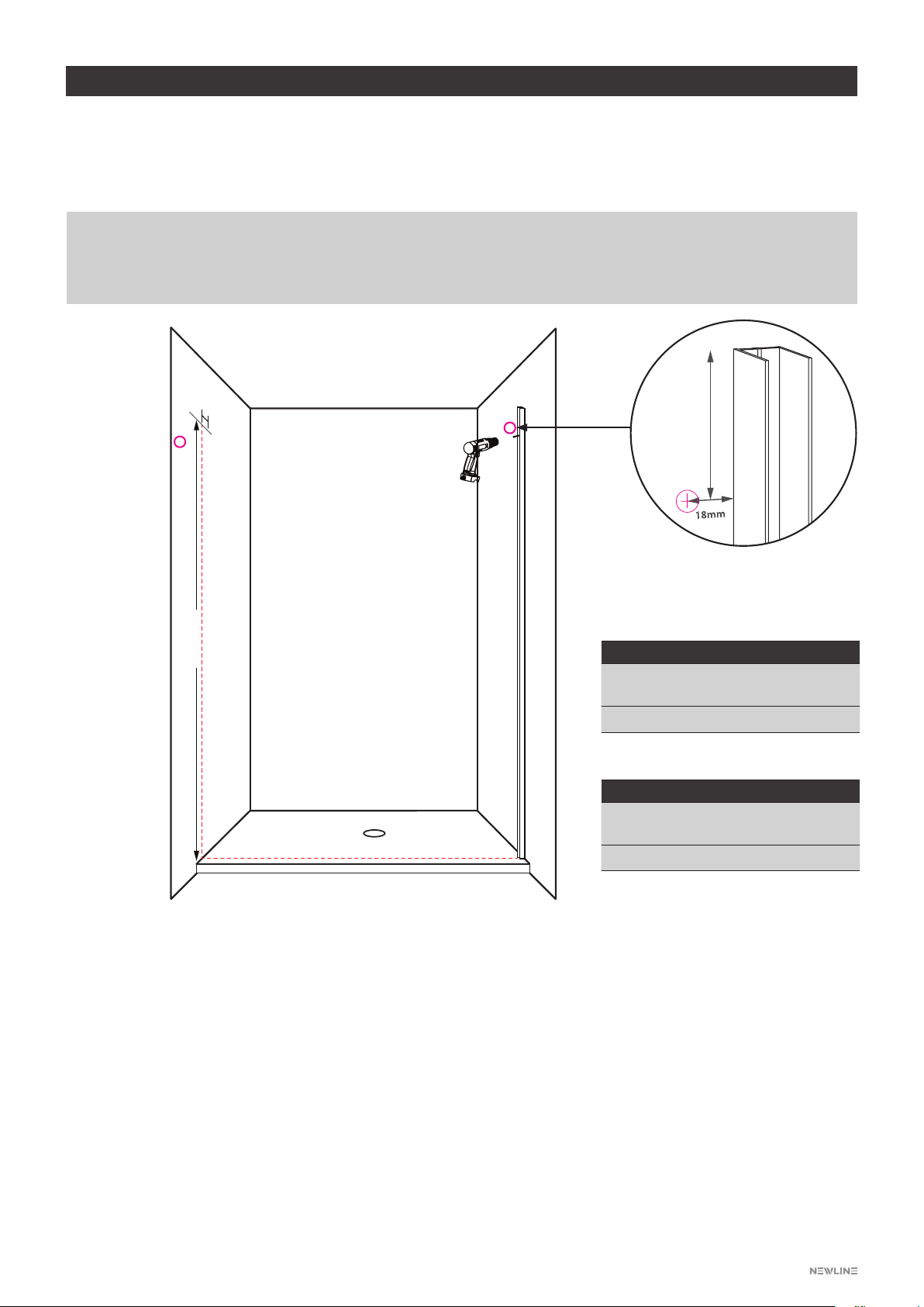
INSTALLATION ACRYLIC 2-SIDED LAYOUT
STEP 1 ACRYLIC
• Mark the two wall proles 19mm back from the outside edge of the tray.
• Use the minimum to maximum table to check this lay-out and adjust if required .
• Predrill the wall proles, align to wall markings and drill a 2mm lead hole in the liner.
• Silicone the back of wall prole and screw in place.
• All details of component assembly can be followed from Step 2, Page 9.
19mm in from
outside edge
Door Rail Mounting
Wall Position
Minimum to Maximum
Door Return
1160 to1172mm 879 to 891mm
92mm
1. Drill a 3mm lead hole in liner ll
with silicone.
2. IMPORTANT! The slot in the
base plate provides adjustment
for slight fall of the top rail to
closing. Up to increase and down
to reduce fall.
3. Fasten mounting plate in position.

7
INSTALLATION TILE 2-SIDED LAYOUT
STEP 1 TILE
• Identify your installation measurement from the table below. Mark outside line of wall proles.
The base proles being 2mm inside this (dotted lines).
• Bond wall proles as outlined in the “Penetration of Waterproong” below.
• Component assembly follows from Step 2, Page 9.
MINIMUM TO MAXIMUM TABLE - WALL TO OUTSIDE OF WALL CHANNEL
ProFinish Tray Size (Before Tiling) Door Set Return Panel
1200x915 1160 to 1172 879 to 891
1200x1000 1160 to 1172 964 to 976
PENETRATION OF WATERPROOFING UNDER TILES
Waterproong warranties are potentially void with penetrations of membrane. Bond wall proles with Bostik V60.
Minimum curing 24 hours (2mm to 3mm). Curing is by atmospheric moisture absorption (approx. 7mm in 7 days).
92mm
Door Rail Mounting
Wall Position
1. Drill a clearance hole in tile, clean
out and ll with silicone.
2. IMPORTANT! The slot in the
base plate provides adjustment
for slight fall of the top rail to
closing. Up to increase and down
to reduce fall.
3. Fasten mounting plate in position.
8
INSTALLATION 3-SIDED ALCOVE LAYOUT
This Diagram covers Acrylic and Tile installations and guidance.
• Acrylic Tray: Positioning the wall prole 20mm off edge of the tray.
• Tile Tray Level Entry: Locate at transition centreline where the slope starts.
• Tray with Hob: Position the boundary line 35mm back from outside of nished hob.
1906mm
37mm
All other installation steps can be now be followed in the instruction steps eliminating the return panel details.
Steps below are distinct to 3-Sided Alcove applications:
Steps run in Conjuction with the 2-Sided instructions.
1. Mark outer boundary line (dotted) across the base and up each wall and the positioning of top rail mounting base
plates on both walls as diagram.
2. Fit wall prole to boundary line (xed glass side only). Fasten as acrylic or tile details on page 6 or 7.
3. Door Rail Mounting: Refer to page 6 for acrylic and page 7 for tile details. IMPORTANT! In the 3-sided alcove
adjustment of rail height requires a slight fall to door shut position.
4. Assemble the rail with stops and rail mount tubes both sides. Attach mounting tubes to base plates on wall. Don’t
fully tighten allen screws onto rail until step 8.
5. Place the xed glass in wall channel.
6. Line up xed glass hole to rail and and install bracket.
7. Plumb up the glass, t to wall prole and screw in place.
8. Finally tighten up the allen key screws in mounting tubes to lock the top rail in place.
These are condensed steps. All other installation steps can now be followed in the instructions eliminating the
return panel details.
MINIMUM TO MAXIMUM TABLE
ProFinish Tray Size
(Before Tiling)
Door Set
1200W x 1000D 1168 to 1180
MINIMUM TO MAXIMUM TABLE
Acrylic Tray Size Door Set
1200W x 915D 1168 to 1180
PENETRATION OF WATERPROOFING UNDER TILES
Waterproong warranties are potentially void with penetrations of membrane. Bond wall proles with Bostik V60.
Minimum curing 24 hours (2mm to 3mm). Curing is by atmospheric moisture absorption (approx. 7mm in 7 days).
92mm
Top Door Rail Mounting
Position
Tile Tray & Walls
Acrylic Tray & Liner
9
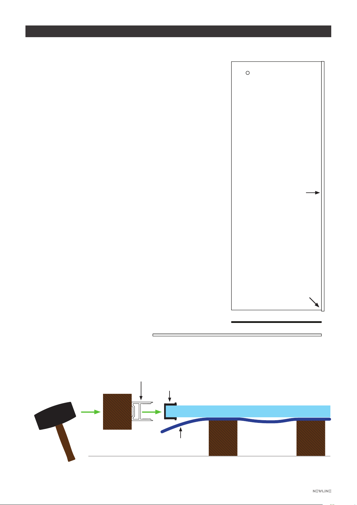
INSTALLATION TILE & ACRYLIC
Diagram A
Wood
Block
Support Support
Rubber Mallet
Floor prole
Seal
Soft protection layer
Fixed Glass Panel
Fixed Front Glass
Knock-on Seal
Floor Profile
Vertical prole
Joint oor to
vertical proles
STEP 2
The fixed glass requires the floor profile with knock-on
seal attached.
Find the three components as drawing
1. Fixed front glass
2. Knock-on seal
3. Floor prole
Assembly Steps:
• Place xed glass onto suitable support with protection
layer as Diagram A.
• Trim the “Knock-on Seal” to length, apply small bead of
NG silicone to leading end and position on glass and join
to vertical prole.
• Ensure there is also a small amount of silicone at join to
seal behind prole in next step.
• Place the oor prole onto seal and push in place
making sure, it is tight against the vertical prole.
• Firmly knock on the oor prole using a short length of
wood working across until fully seated.
• Finish by placing two small beads of silicone underneath
each side of prole join. Clean up excess silicone.

10
INSTALLATION TILE & ACRYLIC
D1
D2
• IMPORTANT! Check the rail has a slight fall down
towards the outside of door. D2 (there is adjustment
in the base plate slot of the rail mounting).
STEP 4
Diagram C1
Diagram D1
• Assemble the door top rail complete with stops
each end and wall mount tube.
• Mounting top rail to return panel, xed front panel
and wall mounting.
STEP 3
Rail mounting
attached to wall
(Align as layout
page 7)
Diagram C2 Corner Clip
• Assemble both xed glass panels and install corner clip to bottom rail.
• Align to wall proles and tray edge.
• Tape position of inside and out of corner.
• Lift corner, support with 5mm packer, apply silicone under oor proles at corner.
• Lower to tape position, clean excess silicone, remove tape and hold with self-adhesive blocks.
CAUTION:
Fit return glass and xed front glass progressively into the wall proles. Horizontal scratches will show on the
glass prole if tting requires shifting out.
DOOR LINE
RETURN
RETURN
DOOR LINE
Cut-out is only
on return panel
Be sure you select the right clip for your corner.
Of the two options provided only one will work.
CORNER CLIPS
IMPORTANT!
11
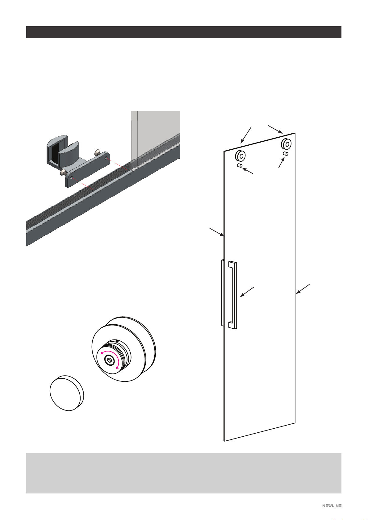
INSTALLATION TILE & ACRYLIC
Diagram E
• Note: Rubber insert in the guide must be removed
and turned to 8mm glass adjustment. Insert tightly
back in place.
• Secure door guide to oor prole.
• Caution: The screw closest to the glass needs a
5mm clearance.
Diagram G
• Rotate cam door adjustment from inside (take
weight of door when adjusting).
Diagram F
• Assembly all parts to door.
• Fit door on top rail and into lower guide.
• Adjust cams to height and alignment.
• Fit lock knobs to door panel.
Rollers
Front Buffer Seal
Handle
Deector Seal
Cut 1860mm high
Lock Knobs
(Fit after door is in
place)
STEP 5
PLEASE NOTE:
If the door line is not parallel to the tray the wall mounted rail bracket can offer some adjustment in or out to
correct this.

12
INSTALLATION TILE & ACRYLIC
Diagram H
• Fasten the shower to wall proles with three 3.5 x 12mm screws and check all ttings are tight (Diagram H).
• Adjust door stops. Ensure the door has a clearance of 25mm at wall and closing to return glass is also
restrained by stop (Diagram I).
Diagram J
• Apply silicone seal to dotted line as indicated.
• Leave for 24 Hrs to cure.
STEP 6
STEP 7
150MM
150MM
Diagram H Diagram I
150MM
150MM
CONTACT
Freephone: 0508 639 5463 Phone: 09 444 2053
Adjust back of
door no closer than
25mm to wall
25mm
Other manuals for Ravello
1
Table of contents
Other NewLine Bathroom Fixture manuals


Popular Bathroom Fixture manuals by other brands


Signature Hardware
Signature Hardware BERWYN 953657 quick start guide

Samo
Samo B7980 Assembly instruction

Luxier
Luxier SP25-CEC quick start guide

Caroma
Caroma ELVIRE installation instructions

IB RUBINETTI
IB RUBINETTI Industria 394 Fitting instructions

Triton
Triton DENE HI-FLO Installation and operating instructions