IB RUBINETTI Industria 394 User manual

ISTRUZIONI DI MONTAGGIO
FITTING INSTRUCTIONS
NOTICE DE MONTAGE
INDUSTRIA
394

IT
DATI TECNICI
Pressione dinamica min:_____________________________________________________________0.5 bar
Pressione MAX di esercizio:____________________________________________________________5 bar
Pressione di esercizio raccomandata:_________________________________________________1-5 bar
Si raccomanda di utilizzare un riduttore di pressione,
se all’interno dell’impianto si hanno pressioni statiche superiori a 5 bar.
Temperatura MAX acqua calda:_________________________________________________________80°C
NORME DI INSTALLAZIONE, MANUTENZIONE E VERIFICHE PRELIMINARI
Perchè il suo apparecchio funzioni nella maniera corretta e possa durare nel tempo, occorre
che vengano rispettate le modalità di installazione e manutenzione illustrate in questo opu-
scolo. Affidarsi ad un idraulico qualificato. Assicurarsi che l’impianto sia stato liberato da tutti
i detriti ed impurità esistenti.
INSTALLAZIONE
Fig. 1: Praticare un foro nel piano Ø34 mm – 1.33 in. Inserire il gambo della bocca, posizionan-
do la guarnizione al di sotto di questa. Fissare la bocca con l’apposito kit di fissaggio.
Fig. 2: Per il miscelatore, ricordiamo che lo spessore massimo del piano deve essere di 15
mm – 0.59 in.
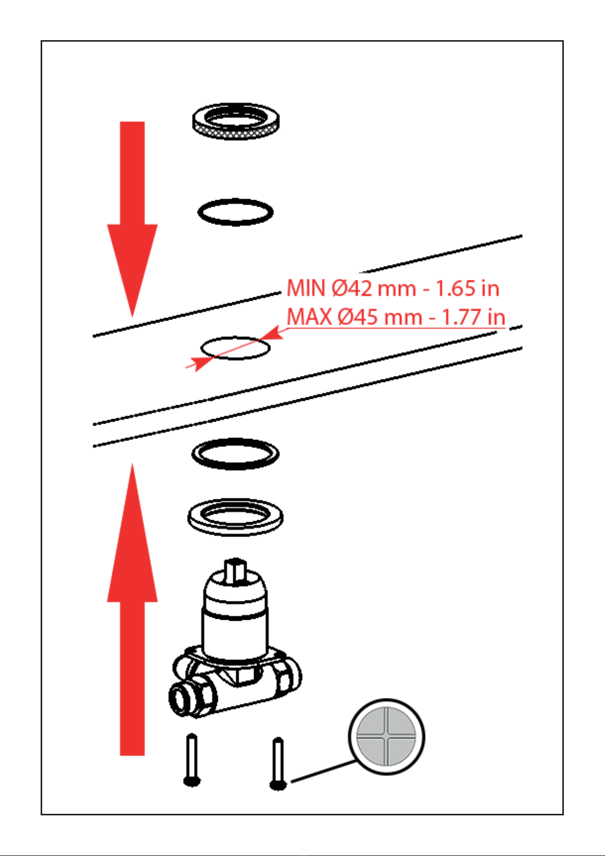
Fig. 3: Realizzare il foro nel piano per il posizionamento del miscelatore, MIN Ø42 mm – 1.65 in
e MAX Ø45 mm – 1.77 in. Pre-avvitare le viti sul gruppo miscelatore. Posizionando l’anello e la
guarnizione. Inserire il gruppo miscelatore da sotto il piano d’appoggio. Posizionare la guarni-
zione al di sotto della basetta, avvitare la basetta sul gruppo miscelatore che sporge dal piano.
Terminare il bloccaggio stringendo le viti.
Fig. 4: Posizionare la maniglia sull’asta di comando, avvitando il grano fino al completo bloc-
caggio. Inserire il tappo copri foro.
Fig. 5: Collegare il flessibile alla bocca.
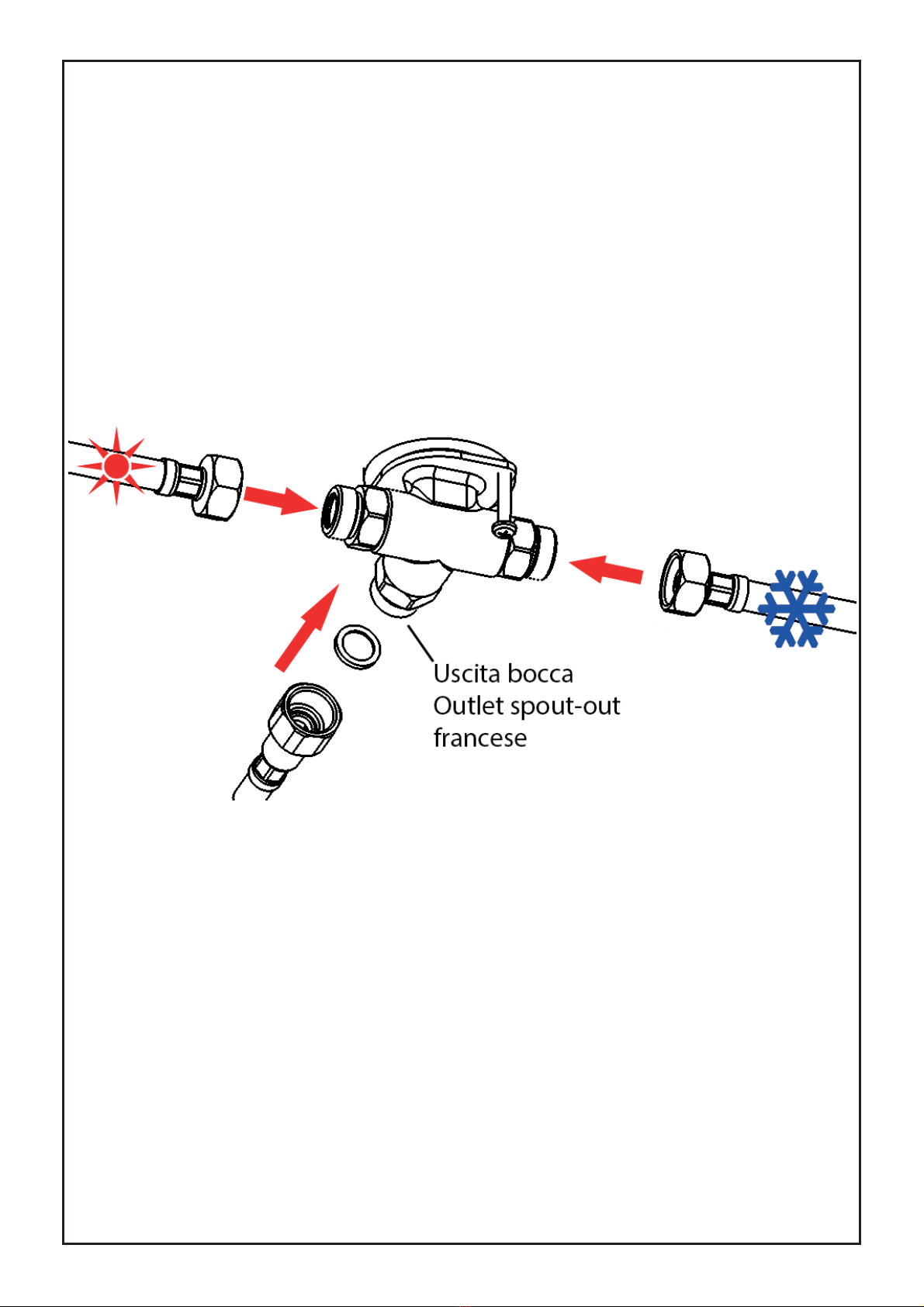
Fig. 6: Collegare il miscelatore alla rete idrica tramite i flessibili. Collegare il flessibile della
bocca all’uscita del miscelatore.
Dopo aver collegato il rubinetto all’impianto, aprire i rubinetti d’arresto e verificare il corretto
funzionamento del miscelatore. Controllare la mancanza di perdite nell’impianto.
PULIZIA
Per una corretta pulizia, lavare esclusivamente con acqua e sapone, risciacquare ed asciugare
con una pelle di daino e panno morbido. Evitare assolutamente l’impiego di alcool, solventi,
detersivi solidi o liquidi contenenti sostanze corrosive o acide, strofinacci con fibre sintetiche,
spugne abrasive, tamponi con fili metallici, poichè potrebbero alterare irreversibilmente le su-
perfici trattate.
L’UTILIZZO DI QUESTO TIPO DI DETERGENTI PER LA PULIZIA DEL RUBINETTO FA DECADERE
QUALSIASI GARANZIA SULLA SUPERFICIE DELLO STESSO DA PARTE DI IB.

EN
TECHNICAL DATA
Minimum dynamic pressure:_________________________________________________________0.5 bar
Maximum operational pressure:________________________________________________________5 bar
Recommended operational pressure:_________________________________________________1-5 bar
It’s recommended to use a pressure reducer in case of
static pressure superior than 5 bar inside the waterpipe.
Maximum hot water temperature:_______________________________________________________80°C
INSTALLATION, MAINTENANCE AND PRELIMINARY CHECKING PROCEDURE
In order to get your device work correctly and fine in time, must ensure compliance with the
mode of installation and maintenance described in this booklet. Relying on a qualified plumber.
Make sure that the system is free from all debris and impurities existing.
INSTALLATION
Fig. 1: Drill a hole in the surface Ø34 mm - 1.33 in. Insert the rod of the spout, positioning the
gasket below it. Fix the spout with the appropriate fixing kit.
Fig. 2: For the mixer, remember that the maximum thickness of the surface must be 15 mm -
0.59 in.
Fig. 3: Make the hole on the surface for positioning the mixer, MIN Ø42 mm - 1.65 in and MAX
Ø45 mm - 1.77 in. Pre-tighten the screws on the mixer unit. Positioning the ring and the gasket.
Insert the mixer unit from under the surface. Place the gasket underneath the base, screw the
base onto the mixer unit that protrudes from the surface. Complete the locking by tightening
the screws.
Fig. 4: Position the handle on the control rod, screwing the grain until it is completely blocked.
Insert the plug covering the hole.
Fig. 5: Connect the hose to the spout.
Fig. 6: Connect the mixer to the water supply with the hoses. Connect the hose of the spout to
the mixer outlet.
After connecting the body to the system, turn on the stopcocks and check that the mixer tap
unit operates correctly. Keep the tap pressurised for a few minutes checking eventual leaks.
CLEANING
In order to obtain a correct cleanliness, exclusively wash them with soap and water, rewash and
dry them with a soft towel and deerskin. Avoid the usage of alcohol, solvents, solid or liquid
detergents which contain corrosive or acidic substances, abrasive sponges, swab with metallic
strings because they could irreversibly compromise the surfaces.
THE USAGE OF THIS KIND OF DETERGNETS DURING THE CLEANING OF THE MIXER EXCLUDE
IB RUBINETTERIE FROM ANY WARRANTY OBLIGATION.

FR
CARACTERISTIQUES TECHNIQUES
Pression dynamique minimale :_______________________________________________________0.5 bar
Pression de service maximale :_________________________________________________________5 bar
Pression de service recommandée :___________________________________________________1-5 bar
Il est recommandé d’utiliser un réducteur de pression en cas,
dans le système hydraulique, il y a des pressions statiques supérieures à 5 bar.
Température maximum d’eau chaude :__________________________________________________80°C
INSTALLATION, D’ENTRETIEN ET VÉRIFICATIONS PRÉLIMINAIRES
Pour assurer le bon fonctionnement du produit et il puisse durer dans le temps, il est nécess-
aire qu’ils soient remplies les procédures de installation et l’entretien définies dans la brochure.
S’appuyer sur un plombier qualifié. S’assures que les tuyauteries soient nettoyées par toutes
saletés et résidus.
INSTALLATION
Fig. 1: Percez un trou dans le plan Ø34 mm - 1.33 in. Insérez la tige du bec en positionnant le
joint en dessous. Fixez le bec avec le kit de fixation approprié.
Fig. 2: Pour le mélangeur, rappelez-vous que l’épaisseur maximale du plan doit être de 15 mm
- 0,59 in.
Fig. 3: Faites le trou dans le plan pour positionner le mitigeur, MIN Ø42 mm - 1,65 in et MAX Ø45
mm - 1,77 in. Pré-serrer les vis sur le mélangeur. Positionnement de la bague et du joint. Insérez
le corps du mélangeur du dessus du plan. Placez le joint sous la rosace, vissez la rosace sur le
cops du mélangeur qui dépasse du haut. Terminez le verrouillage en serrant les vis.
Fig. 4: Positionnez la poignée sur la tige de commande en vissant le grain jusqu’à qu’il soit
complètement bloqué. Insérez le bouchon cache trou.
Fig. 5: Connectez les flexibles au bec.
Fig. 6 : Connecter le mélangeur à l’alimentation en eau avec les flexibles. Connectez les flexi-
bles du bec à la sortie du mitigeur.
Après le raccordement du robinet aux tuyauteries, ouvrir le robinet d’arrêt pour vérifier le bon
fonctionnement. Vérifier l’absence de fuites.
NETTOYAGE
Afin d’assurer un bon nettoyage, laver exclusivement avec eau et savon, rincer et essuyer avec
un chiffon doux. N’utiliser jamais alcool, solvants, de poudres à récurer ni de nettoyants acides
et éponges abrasives ou éponges métalliques car risquent de causer des dommages irrémédi-
ables.
L’UTILISE DES CES DETERGENTS POUR LE NETTOYAGE DU MITIGEUR REND CADUQUE LA
GARANTIE SUR LA SURFACE DE-CI PAR IB.

Fig. 1

Fig. 2

Fig. 3

Fig. 4

Fig. 5

Fig. 6

SOSTITUZIONE CARTUCCIA
Chiudere le entrate dell’acqua fredda e calda.
Estrarre il copriforo q, svitare il grano w utiliz-
zando una chiave esagonale da 2 mm e sfila-
re la maniglia e. Svitare il copri ghiera re la
ghiera tutilizzando una chiave esagonale da
27 mm, estrarre la cartuccia y. Per il montag-
gio procedere in ordine inverso, assicurandosi
che la base d’appoggio della cartuccia sia ac-
curatamente pulita.
CHANGING THE CARTRIDGE
Turn off the hot and cold water inlets. Remo-
ve the hole plug q, unscrew the grubscrew
wusing an allen key of 2.5 mm and remove
the handle e. Unscrew the ring nut cover r
and the ring nut tusing an hexagonal 27 mm
wrench, extract the cartridge y. To reassem-
bled, reverse the above procedure, making
sure that the cartridge contact surface is tho-
roughly cleaned.
CARTOUCHE DE REMPLACEMENT
Couper l’eau froide et chaude. Retirez le bou-
chon q, dévisser la vis w, à l’aide d’une clé
hexagonale de 2,5 mm et retirez sur la poi-
gnée e. Dévisser le bague rde recouvre-
ment ten utilisant une clé hexagonale de 24
mm, retirez la cartouche y. Pour le montage,
procéder dans l’ordre inverse, en veillant à ce
que la base de support de la cartouche soit
soigneusement nettoyé.

Table of contents
Other IB RUBINETTI Bathroom Fixture manuals
Popular Bathroom Fixture manuals by other brands

Kohler
Kohler K-4777 Installation and care guide

AQUA SPHERE
AQUA SPHERE LOIRE 74809 installation manual

Helvex
Helvex PIAZZA PIA-200 installation guide

OVE
OVE TAMPA installation manual

Hans Grohe
Hans Grohe AXOR Montreux 16530 Series Assembly instructions

Arblu
Arblu DEDALO PLUS ANGOLO Q-R 1AB Plus 1LF Assembly instructions

unidrain
unidrain 1001 Construction Guideline

agape
agape MARSIGLIA ACER0705M Assembly instructions

Franke
Franke EXOS676X Installation and operating instructions

ProFlo
ProFlo PF3880CP instructions

Peerless Faucet
Peerless Faucet Core PTT188743 quick start guide

VADO
VADO WG-81389-C Installation & maintenance instructions